
Fundamentals of Power Electronics Controlled Electric Propulsion
Shailendra Jain Maulana Azad NIT, Bhopal, India
Lalit Kumar NIT, Raipur, India
Abstract
In recent years, growing concern about environmental protection, stringent emission regulation, and rapid depletion of fossils fuels enforced to look forward for sustainable alternatives of road transportation system. Electrification of vehicular technology (EVT), partial or complete, is emerged as a promising and sustainable alternative for road transportation system. EVT has engaged auto manufacturers and researchers to primarily focus on fuel economy, driving range, performance, and costs. These parameters are influenced by the design and performance of electric propulsion system (EPS). EPS involves integration of electric, mechanical, chemical, and electronics engineering in a one platform that is a major challenge and needs to be taken care properly. Power electronic converters (PECs) and switches are playing significant role in compatible integration and proper coordination among different components of EPS. Thus, in this chapter, different configurations of electrified vehicles are presented along with their current status, technical challenges, futures issues, and market penetration. To present the study in synthesis, important constituents of EPS are discussed briefly, and comparative analyses are made in terms of present trends, ongoing technological advancements, and future challenges. The importance of power electronic converters has been emphasized, and detailed study on the role of power electronic converters in different segments of electrified vehicles has been discussed.
Keywords
Electric vehicular technology; Electric propulsion system; Electric vehicle; Hybrid electric vehicle; Power electronic converter; dc/dc converter; dc/ac converter; Electric motor; Energy storage system
31.1 Introduction
After the energy-generating industries, transportation system is utilizing a big part of world's energy resources. Thus, it is responsible for a comparable share of environment pollutants caused by the combustion of fossil fuel (viz. petrol, diesel, and ethanol) [1]. A global transformation of transportation system for environment protection, energy conservation, energy-efficient system, and low-carbon emission will require significant improvement in the process of onboard energy production and its efficient consumption [2–4]. This technological transformation requires systematic development of fuel- and energy-efficient technologies in transportation sector.
31.1.1 Motivations for Vehicular Electrification
Conventional transportation system employs internal combustion engine (ICE)-based propulsion system, which uses petroleum products for propulsion. It is estimated that, at the present consumption rate, the current global petroleum resources will be used up within the next 50 years [4]. It has also raised growing concerns about environmental pollution and subsequent climate changes. For example, in the United States of America (USA), conventional transportation system accounts for 30% of total greenhouse gases (GHG) emission, causing significant global warming [3]. Moreover, it is projected that world population will increase from the existing 6 billion to around 10 billion in the next 50 years while the number of vehicles in operation is set to increase from 700 million to 2.5 billion [4].
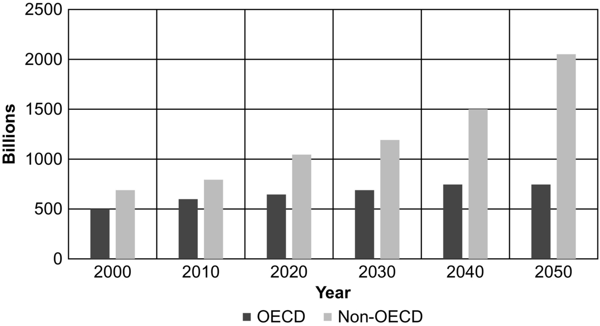
With the projected growth of small cars and its CO2 emissions, the importance of addressing fuel efficiency in road transport is significantly important on global environment, energy, and climate change agendas. Road transportation system is responsible for approximate 20% of global CO2 emissions from fossil-fuel combustion, and in most countries, CO2 emissions from transportation are growing at a faster rate than total CO2 emissions [2,3]. Projections for road transport growth and car ownership for the next few decades as shown in Fig. 31.1 show that road transport will continue to dominate, despite the rapid growth in shipping and aviation sectors.
Significant fuel economy improvements and reduction in tailpipe emission in road transportation sector are required to stabilize and reduce greenhouse gas and CO2 emissions. The United Nations Intergovernmental Panel on Climate Change (IPCC) states that an ambitious 50%–80% reduction in global CO2 emissions is required by 2050 (as compared with 2000 levels) in order to limit temperature rise to 2–2.4°C and stabilize atmospheric CO2 concentration at 450 ppm, thus avoiding severe climate change [2,3]. Doubling the fuel efficiency of road vehicles is one of the most cost-effective and accessible measures toward achieving global stabilization of CO2 emissions. However, the targets for both reduction of global CO2 emission and improvement in fuel efficiency require that all countries should adopt cleaner technology on a large scale. Given this scenario, meeting the worldwide energy demand for the present and future transportation systems with the least impact on the environment is an important challenge in terms of technological and societal development.
In order to meet this challenge, novel concepts and innovations are being infused to make transportation systems more and more energy-efficient, reliable, and safe with zero or reduced emissions at an affordable cost. These novel concepts and innovations can be seen in terms of use of low-carbon fuel such as bioethanol or biodiesel, substitution of the petroleum energy by electric energy to drive vehicles, and hydrogen-based power generation. [4]. Majority of these innovations are solely relying on electrification of conventional vehicular technology and are grouped under the genre of electric vehicular technology (EVT). In EVT, ICE-based propulsion systems are being replaced by electric propulsion system (EPS), either partially or fully, to minimize fuel consumption and tailpipe emission. Vehicles that employ EVT can be broadly classified as follows [5–15]:
▪ Battery electric vehicles (BEVs)
▪ Hybrid electric vehicles (HEVs)
▪ Plug-in hybrid electric vehicles (PHEVs)
▪ Fuel-cell vehicles (FCVs)
BEVs are mainly the combination of energy storage system (ESS) and electric propulsion unit that together constitute the power to propel the wheels. Limited operating range and comparatively poor performance and limitation of storage system are the major concerns with BEVs. HEVs are the combination of BEVs and ICE vehicles to bring the advantages of both the vehicles together. Hybrid technologies can be used for almost all kinds of energy sources and engines. The additional electric and mechanical components make the HEVs more complex, bulkier, and costlier. PHEVs are the integration of EVs and HEVs to extend the degree of electrification and electric driving range of the vehicles to achieve the higher efficiency and reduced emission. However, infrastructures for charging stations are major concern. FCVs use hydrogen as fuel to produce electricity; therefore, they are basically emission-free.
31.1.2 Advancement of Electric Vehicular Technology
In the last decade, EVT is accelerated globally as competitor and sustainable alternatives of conventional ICE-based vehicles. Efforts and substantial resources are directed to meet market expectations for high-performance, energy-efficient, durable, safe, and affordable electrified vehicles [5]. The technological development and growth of EVT has taken on an accelerated pace on their road map to overcome the abovementioned issues associated with each of the electrified vehicles. Therefore, the dream of having commercially viable EVs/HEVs/FCVs/PHEVs is becoming a reality. EVs/HEVs are gradually commercializing and capturing the significant market space; PHEVs are ready to be commercialized, whereas FCVs are under development and yet to be commercialized [5–13]. The vision of vehicular electrification also includes generating electricity more and more from carbon-free and renewable energy sources such as wind, solar, hydro, fuel cell, and using them in transportation [12]. The next generation of electrified vehicles will therefore be integrated with electric power systems through EVs and PHEVs that will enable to implement grid-to-vehicle (G2V) and vehicle-to-grid (V2G) concept and will reduce environmental footprint significantly [12–14]. The world-wise sales of BEVs, HEVs, and PHEVS are presented in Fig. 31.2.

In the last decade, successive development in vehicular electrification brought back the electrified vehicles specially HEVs in competition with ICE vehicles in terms of dynamic behavior, driving range, and practicability with added advantage of higher efficiency, reduced emission, and globally emerged as sustainable alternative of conventional ICE-based vehicles [5–10]. Therefore, at present, major attention has been focused on technological advancement and modernization of HEVs. Moreover, automobile industries are shifting toward more fuel-efficient, improved performance, higher degree of reliability, durability, safety, and added comforts. Thus, significant efforts and resources are being spent by leading car manufacturers and government to meet these market expectations at an affordable cost [16].
31.1.3 Hybridization of Energy System for EVT
In an EVT, the onboard energy sources are limited and acting as bottleneck of the technology [17]. However, it is essential that the power requirement of vehicle load should be met on board. It is impractical and very expensive to size a single-source energy system to offer continuous power with a capacity many times higher than the average power demand, just to meet momentary peaks in power needs. Therefore, adopting multiple energy sources on board that are specialized for the various segments within a vehicular power demand bandwidth becomes a viable solution [17]. The combination of storage system with high-energy-density specifications and storage system with high-power-density specifications provides sustainable solutions [18]. The task of a power and energy management system then is to properly coordinate the dynamics of the energy systems without compromising the vehicle's targeted performance [19].
In EPS, none of the available energy sources are capable enough to meet power and energy requirement of the vehicle for all driving profile [18]. In recent years, it has been observed that to fix the onboard energy demand of electrified vehicles, there is need to mix the energy sources. This encapsulates the idea that the solution to problem of meeting onboard energy demand is hybridization of diverse energy sources such as fossil fuel, solar, hydrogen, and portable source of electric energy like battery, ultracapacitor, and fuel cell.
As an alternative to onboard single-source energy system, hybridization of energy sources is considered as durable and sustainable energy system. HES is gaining more and more popularity in vehicular electrification due to their ability to provide high-power and high-energy-density systems. A well-designed HES offers features like reliability, durability, cleanliness, and efficient power processing operation compared with single-source energy system [17–20]. It provides optimum solution between availability and utilization of energy sources and offers good power-handling capability in steady-state operation and superior dynamic response during transient conditions.
31.1.4 Power Electronics for EVT
The integration of different components from different branches is a major challenge and is a growing concern in the road map of vehicular electrification. PECs and switches are playing a very significant role in incorporating different components and provide compatibility for proper coordination among them to meet vehicle's requirement in all driving profiles [21–25]. Advancement in power electronic devices is an enabling technology for the next generation of vehicles that offers smarter, efficient, cleaner, precise, environmentally friendly, and more flexible drive. The reasons for rapid acceleration in growth of vehicular power electronics as discussed in [23] are as follows:
▪ The new vehicle architecture integrated with power electronics makes the switching and fusing functions through single component with higher degree of reliability.
▪ Integrated of sensing technique with power electronic devices enables easy fault detections and diagnosis and makes system capable for fault-tolerant operation.
▪ PECs make on demand power conversion as per auxiliary load profile and for propulsion motor resembling the functions of adjustable speed drives.
▪ Voltage conversion for different voltage level especially in dual-voltage architecture and dc/ac and ac/dc conversion can be done using power electronics.
▪ Power electronics devices are used in the development of electronically controlled actuators and variable valves with high degree of precision and accuracy.
▪ Power electronics with modern digital signal controller provides very fast and high-power motion control of propulsion system by enabling high-power actuation and dynamics.
Power semiconductor devices constitute the heart of modern power electronic apparatus, and today's power electronic evolution has been possible primarily due to evolution in power electronic devices [21]. In the past few years, power device technology has made remarkable progress and grown in power rating and performance by an evolutionary process.
For EVT, there is a need of highly reliable, flexible, and fault-tolerant EPS. Suitable integration of ESS, power electronic converters (PECs), electric motors (EM), and electronic control unit (ECU) makes the EPS to compete against the conventional ICE-based vehicle [25]. The responsibility of integration of these components is well taken care by power electronic devices. A PEC, consisting of a matrix of power semiconductor switches and one or several passive components, helps to convert and control electric power from one form to another form at different voltage and current profile between ESSs and EMs according to the driving profile of the vehicle. PECs act as an interfacing medium for the hybridization of different energy sources like battery, ultracapacitor and fuel cell to match the onboard power and energy requirement. For vehicle acceleration, PECs take power from onboard energy system and supply power to the electric motor as per the demanded vehicle operation. On the other hand, PECs can also be used to utilize recovered energy during deceleration and regenerative braking to charge ESS. The electronic controllers composed of sensors, digital signal processors, and interfacing circuitry are used to generate the control signals for PECs [26].
Power electronics is an enabling technology for efficient electric power processing, which plays crucial role in shifting paradigm from conventional ICE vehicles to electrified vehicles [22,25]. The demand of electric power in vehicular application is growing rapidly as the mechanical components are being replaced by the electric and electronic components. It is expected that the power demand in electrified vehicle could reach 2–3 times of the current demand [23]. In order to accomplish the growing power demands of electrified vehicles in desired manner, integration of power electronic components with electric and mechanical loads of the vehicle becomes crucial [24]. The integration of PEC not only improves the overall performance and fuel economy but also reduces the emission as well as weight and size of the EPS.
31.2 Electric Vehicular Technology
The development process of the electrified vehicles is interesting, as the first battery-operated electric vehicle is invented in 1834 [8]. Due to the lack of technology, primarily for electrochemical storage units, the interest in EVs gradually diminished and ceased to receive any attention after 1920. In the early 1970s, circumstances changed in favor of the electrified vehicle concept due to the dramatic increase in petroleum prices, global awareness about environmental pollution, and stringent emission regulation [8]. The research on EVT is motivated by the argument that electric vehicles represent an economical and technically sustainable option for future transportation systems. Environmental impacts, escalating prices of petroleum fuels, emission restrictions, and the depletion of natural resources provide compelling impetus toward the development of more eco-friendly solutions. It represents one of the greatest challenges of today, a challenge that calls for sustainable advancements and development of EVT.
EVT, essentially, has two major components:
(1) Vehicle architecture and configuration
(2) Electric propulsion system that includes
▪ energy storage system (ESS),
▪ power electronic converter (PEC),
▪ electric motor (EM),
▪ electronic control unit (ECU).
There are plenty of review papers and literature that deal individually with topological architecture and configuration [4–15,27–29], energy source and storage systems [17–20,30–47], electric machines [21,48–62], power electronic converters [21–25,63–75], and power-flow management and control strategy [76,77]. This section discusses the architecture of HEVs that includes series, parallel, series-parallel, and complex HEV.
31.3 Classification of Electric Vehicular Technology [6]
The vehicular technology can be classified as ICE-based vehicles and EPS-based vehicles or electrified vehicles. Electrified vehicles that are driven by EPS either fully or partially further are classified as EVs, HEVs, PHEVs, and FCVs. In EVT, each vehicle has its own capability and limitation in terms of energy density, power density, emission rate, performance, fuel efficiency, size, weight, cost, and safety [4–10]. These factors are heavily governed by the particular vehicle architecture and propulsion system configuration. Out of the several class of electrified vehicle mentioned above, HEV is the only option that has potential to compete the ICE vehicles in terms of performance. The major advantages of HEV are extended electric range of operation, good fuel economy, higher efficiency, and sufficient onboard power and better dynamic response. Different characteristic such as size versus distance characteristic is depicted in Fig. 31.3, whereas driving distance of some popular BEVs, HEVs, and PHEVs commercialized so far is given in Table 31.1 along with their associated benefits.

Table 31.1
Characteristic of different electrified vehicles
| S.No | Car Model | Range (miles) | Top Speed (mph) | Charge Time (hrs) | Battery (kWh) | Rated output (HP) | Acceleration (0-60 mph) |
| Battery Electric Vehicle | |||||||
| 1 | Smart Fortwo Electric | 70-80 | 81 | 2.5 | 17.6 | 80 | 11.4 s |
| 2 | Ford Focus Electric | 115 | 84 | 5.5 (240V) | 33.5 | 143 | 9.9 s |
| 3 | Nissan Leaf | 107 | 93 | 9.5 | 30 | 107 | 9.9 s |
| 4 | BMW i3 | 114 | 93 | 4 | 33 | 170 | 7 s |
| 5 | Kia Soul EV | 132 | 90 | 4-5 | 27 | 109 | 10.8 s |
| Hybrid Electric Vehicle | |||||||
| 6 | Toyota Prius Plus | 640 25 on battery |
103 | 2 | 8.8 | 121 | 10.5 s |
| 7 | BMW i8 | 310 23 on battery |
155 | 2-3 | 7.1 | 357 | 4.2 s |
| 8 | Chevy Volt 2nd Generation | 420 53 on battery |
100 | 13 (120V) | 18.4 | 84 (Engine) 74 (Motor) |
9.2 s |
| 9 | Honda Accord Hybrid | 758 On battery NA |
112 | NA | 1.3 | 212 | 6.9 s |
| 10 | Volkswagon Jetta Hybrid | 571.2 On battery NA |
185 | NA | 1.1 | 170 | 7 s |

⁎ NA – Not Available
31.3.1 ICE Vehicles
A conventional ICE burns a high-energy-density petroleum fuel (gasoline/diesel) in its combustion chamber and produces power that can be utilized to propel the vehicle by means of mechanical transmission. An ICE-based power train is shown in Fig. 31.4. It consists of a fuel tank that provides onboard high-density-energy source, the internal combustion engine, and a mechanical transmission to transport the power from engine to wheel. The ICE vehicles score in driving distance because of the high energy density of liquid hydrocarbon fuels and dominate in recharging times as a refilling station takes minutes, compared with hours of battery charging time in electrified vehicles [6,29]. The main drawbacks of the conventional ICE vehicles are poor efficiency to convert the fuels into useful power and excessive tailpipe emission, which produces harmful impact on the environment. It has been proved that the maximum fuel conversion efficiency of conventional ICE-based vehicles is 25%–30% at best [6,7]. The main reason of inefficiency of ICE vehicles is the mismatch of engine power characteristic with the real load characteristic of the vehicles as shown in Fig. 31.5, poor efficiency of mechanical transmission and waste of kinetic energy during braking [29]. Although internal combustion engines have been used for more than a century, significant improvements in fuel economy, energy efficiency, and emission reduction have been achieved, and still, great research for optimization is going on.


31.3.2 Battery Electric Vehicles
New environmental concerns over the amount of pollutants released into the atmosphere by internal combustion engines (ICE), unstable petroleum prices in international market, and various emission regulations such as the California Air Resources Board (CARB) have mandated the concept of zero-emission vehicle (ZEV). This becomes a powerful motivation for the use of battery electric vehicles.
The concept of electric vehicles is based on electric drives that consist of the electric motor, power modulator, and onboard energy source and a controller. A simplified architecture of a BEV is shown in Fig. 31.6. A BEV has various advantages such as zero emission, high efficiency, independence of petroleum fuels, less noise, safe, and smooth operation. Moreover, while the maximum efficiency of the ICE vehicle can be 30%–35%, electric propulsion system drawing the power from battery can operate with a peak efficiency of 90% [4–8]. Also, electric vehicles have the capability to recover the waste energy through regenerative braking.

Apart from significantly large battery charging time, lower flexibility, and dynamic performance, an important limitation of BEV is its limited operating range per cycle of battery charge. For BEVs to compete against ICE vehicles, advanced energy sources and intelligent energy management system would play key roles.
31.3.3 Hybrid Electric Vehicles
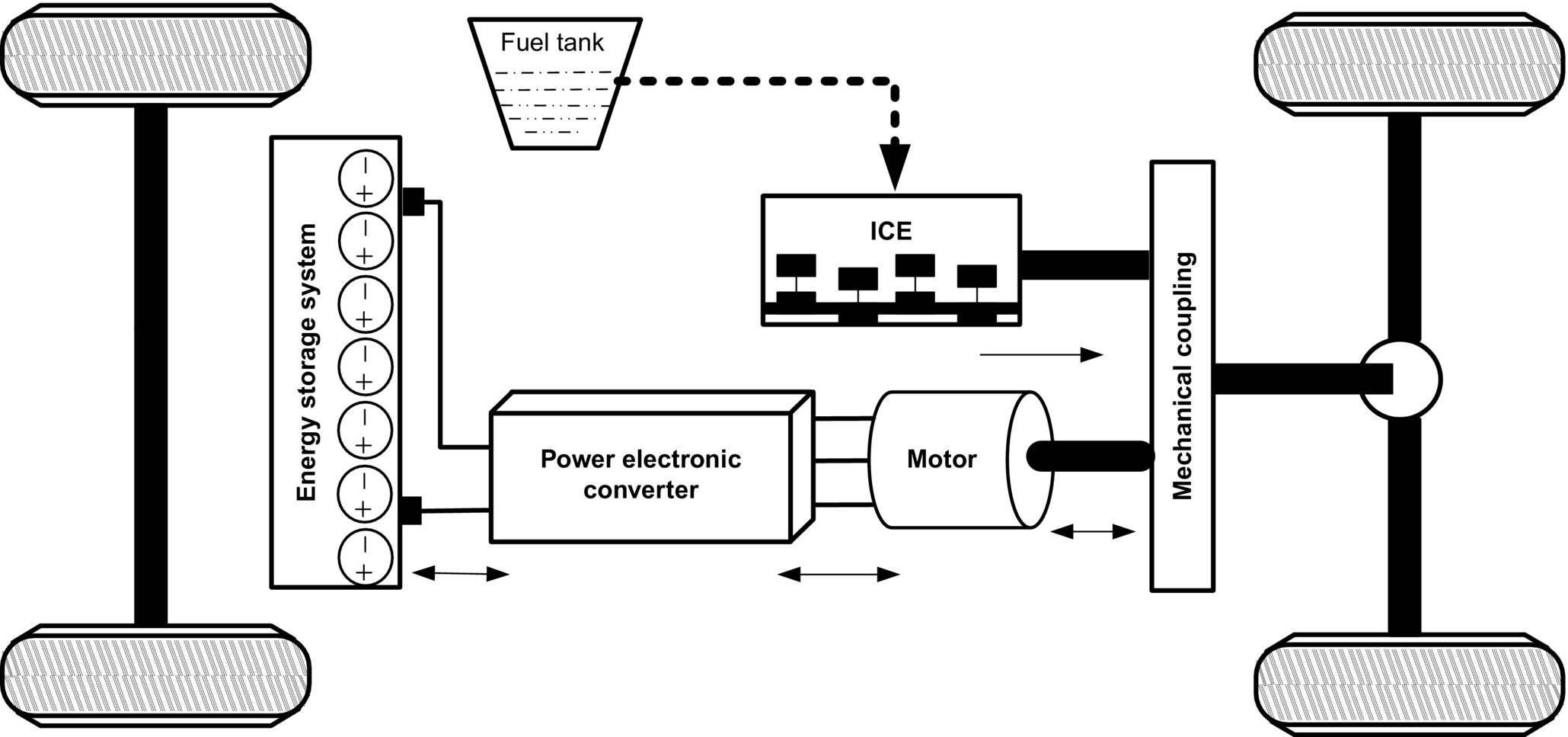
A hybrid electric vehicle (HEV) is powered by the existing ICE technology and a suitable electric drive system. According to technical committee 69 (electric road vehicles) of the International Electrotechnical Commission, “a hybrid electric vehicle (HEV) is a vehicle in which at least one of the ESSs or converter can deliver electric energy.” Conceptually, HEV uses two energy sources, namely, a fuel (like gasoline, diesel, and hydrogen) and stored energy (as in battery, ultracapacitor, and flywheel), to propel the wheel. The concept of HEV is to combine the EV and ICE vehicle so that better fuel utilization, good dynamic performance, and reduced tailpipe emission can be achieved, and their respective limitations can be overcome [6–9].
The major advantages of HEV are extended electric range of operation, good fuel economy, higher efficiency, and sufficient onboard power to meet the vehicles' demand in all driving profile. Combining automobile technology with electric technology adds complexity in controls and makes the system heavier and costly. Management and control of power flow from more than one energy sources to the load is a major concern and has to be treated in an optimized way so that better utilization of energy at predicted cost is achieved [6,10]. Fig. 31.7 shows the conceptual power-flow diagram of HEV.

To meet the desired load demand and to optimize the utilization of energy source(s), there are following possible operating modes to combine the two energy sources as illustrated in Fig. 31.7:
Mode I—Energy source A alone supplies power to the load.
Mode II—Energy source B alone supplies power to the load.
Mode III—Both energy sources A and B supply power to the load simultaneously.
Mode IV—Energy source B draws power from energy source A.
Mode V—Energy source B draws power from load at the time of braking (regenerative braking).
Mode VI—Energy source A supplies power to energy source B and the load simultaneously.
Mode VII—Energy source B draws power from energy source A and load simultaneously.
Mode VIII—Energy source A supplies power to energy source B, and energy source B supplies to the load.
Mode IX—Energy source A supplies power to load, and load supplies power to energy source B.
Energy source A could be gasoline/diesel/fuel cell, and power converter A is unidirectional in nature and converts chemical energy into mechanical energy. Energy source B could be a battery and/or ultracapacitor, and power converter B is bidirectional in nature and delivers electric output. Topological configuration of HEVs is based on energy utilization scheme of energy sources. In the automobile industry, development trends are toward mounting sophisticated electric systems and replacing various mechanical and hydraulic systems to provide more comfort and to increase safety [8].
HEVs are traditionally classified into four categories: series hybrids, parallel hybrids, series-parallel hybrids, and complex hybrids, where the entire configuration brings together the electric and mechanical power through various components.
31.3.3.1 Series Hybrid Electric Vehicles
A series hybrid is an HEV that has two energy sources empowering an electric motor that propels the vehicle. SHEVs are the simplest form of HEVs in which an ICE is mechanically coupled with an electric generator that, in turn, is connected to the electric motor and electrochemical battery pack through a power electronic converter as shown in Fig. 31.8. With the help of generator, mechanical power of ICE is transformed into electric power. The transformed electric power can be used to charge the battery or can evade the battery to supply the electric motor to propel the vehicle, or both can happen simultaneously by means of power electronic converter [5,10]. The power flow from fuel tank to power electronic converter is unidirectional and from battery to electric motor is bidirectional.

Basically, it is ICE-based EVs where there is no mechanical link between ICE and wheel. The start/stop of ICE is controlled by the battery state of charge (SOC). When the battery reaches at a preset minimum SOC, the ICE starts in order to charge the battery. The ICE stops when the battery has reached a desirable maximum SOC. The control algorithm for the optimal operation of engine, having high efficiency and low fuel consumption, is selected such that the battery SOC should be maintained at around 65%–75% of full charge [9]. However, power transportation from energy sources to the wheel takes two stages of power conversion (mechanical to electric and electric to mechanical) and leads to increased energy losses and reduction in overall efficiency of the vehicle. All possible combinations (modes I–IX) of two energy sources are applicable for the SHEVs, but practically, only modes I–VI have been used so as to extend the life of battery [6]. The mechanical decoupling between the engine and wheels increases the degree of flexibility and reduces the complexity. Since the electric motor has the desired torque-speed characteristic, multigear mechanical transmission system can be eliminated. Simplified construction, control strategy, and reduced costs are the salient features for such a system. However, addition of generator and size of propulsion unit are two major concerns. The SHEVs are best suited for city driving where frequent “starts” and “stops” occur over a part of distance being traveled [5].
31.3.3.2 Parallel Architecture
In a parallel hybrid configuration, ICE and electric motor are connected in parallel to deliver power to the wheel as shown in Fig. 31.9. The powers from electric motor and ICE are pooled together with the help of mechanical coupling. However, the mechanical coupling adds to the complexity in control algorithm for the vehicle. The vehicle can be driven with the ICE, the electric motor, or both simultaneously, and therefore, it is possible to feed the desired amount of power at any given period of time [5–10]. In parallel HEV, except modes VII, VIII, and IX, all other modes (I–VI) can be used for better utilization of energy sources and reliable operation [6]. In this configuration, efforts are made to operate the electric motor alone at lower speed and ICE alone at higher speeds. Thus, at higher speed, ICE is operated at most efficient point, and hence, higher efficiency and better fuel consumption along with reduced tailpipe emission can be achieved. In case of acceleration or hill climbing, both the power sources are activated to fulfill the desired power demand. When ICE is working alone or in case of regenerative braking, the electric motor can operate as a generator to charge the battery.
As compared with series HEV, elimination of generator leads to single-stage power conversion that increases the efficiency and reduces the weight and cost of the vehicle. The parallel coupling of the power sources leaves space for further research and improvement of vehicle's performance. The major research efforts on parallel HEVs are focused on the implementation of continuously variable transmission (CVT) instead of a fixed-step transmission that gives the freedom to operate the ICE at its most efficient point at demanded torque [9].
31.3.3.3 Series Parallel Architecture
Series-parallel HEV is an integration of the series and parallel hybrids as shown in Fig. 31.10. The configuration introduces an additional mechanical link (unlike the series hybrid) and an additional generator (unlike the parallel hybrid) to facilitate the advantages of both configurations [4–10]. Among various possibilities in series-parallel hybrids, the general classification includes electric-intensive and engine-intensive. In electric-intensive configuration, electric motor is more dominating than the ICE. In engine-intensive configuration, ICE is more dominating than electric motor [10]. Accordingly, the dominating components are designed. The operating modes (start, normal driving, acceleration, deceleration, braking, and battery charging) of electric-intensive and ICE-intensive are almost the same except for the normal driving mode. In normal driving mode, efforts are made to operate the engine at its most efficient point. Therefore, in ICE-intensive configuration, the engine propels the wheels solely, and in electric-intensive configuration, the ICE can assist the electric motor to propel the wheels. Although the series-parallel hybrid vehicle incorporates the advantages of both the series and parallel hybrid, the use of additional electric and mechanical components (generator and planetary gear arrangement) adds to the complexity, weight, and costs.

31.3.3.4 Complex Hybrid System
All the configurations discussed previously are implemented for single-axle propulsion, for either the front or the rear wheel. A new hybrid scheme known as complex hybrid configuration is designed for dual-axle propulsion. In such an architecture, illustrated in Fig. 31.11, both the front and rear wheels propel the vehicle. In this configuration, the front-wheel and rear-wheel axles are decoupled from each other, and there is no mechanical link between them; hence, both the axles are driven independently [10]. In complex hybrid vehicle, the electric generator offers bidirectional power flow, whereas in case of series-parallel, it offers unidirectional power flow. However, both the configurations involve ICE, electric generator, and motor to propel the vehicle. The capability of complex hybrid system, to drive the wheels by either electric propulsion or hybrid propulsion or combination of both, offers additional flexibility and reliability. The front wheels are propelled by hybrid propulsion system, and rear wheels are propelled by electric propulsion system or vice versa. The operating modes for both the scheme are almost common, except when front wheels are propelled by hybrid system, all the wheels are driven; however, when front wheels are propelled by electric system, only front wheels are driven at starting [8–10]. A planetary gear arrangement is used to coupled ICE, front electric motor, and front axle altogether. Independent control of front and rear wheels provides smooth vehicle operation and flexibility in casing. This, however, increases complexity and costs. Also, regenerative braking in all four wheels can significantly improve efficiency of the system and hence fuel economy.

31.3.4 Plug-in Hybrid Electrical Vehicles
Plug-in hybrid electric vehicle is a transitional technology between BEVs and HEVs. The IEEE (board of directors, 2007) defines a PHEV as “any hybrid electric vehicle that contains at least (i) a battery storage system of 4 kWh or more, used to power the motion of the vehicle; (ii) a means of recharging that battery system from an external source of electricity; and (iii) an ability to drive at least 10 mi in all-electric mode, and consume no gasoline” [15]. Conceptually, a PHEV is a HEV with large battery pack that can be recharged from the external source (utility grid or renewable source of energy) to extend the all-electric range (AER) of the vehicles as shown in Fig. 31.12.

In this vehicle, fuel tank and battery pack both can be recharged by external sources and are entirely different from hybrid vehicles that do not utilize any electric energy from the external sources or grid. When the battery pack is fully charged by external source, PHEV operates as EV with extended AER (30–60 km) and then switches to hybrid mode when battery reaches its predefined SOC or vehicle demands extra power for acceleration [13,14]. Moreover, not only PHEV has the capability to charge the battery pack from the grid, but also it will be able to supply the power to the grid, and hence, the vehicle-to-grid (V2G) concept is evolved [15]. The emerging technology of V2G must be bidirectional in nature so that grid can transfer power to the vehicle in charging mode, and vehicle delivers power to the grid in discharging mode at peak hours. All vehicles with V2G capability must meet the IEEE Standard 1547 for connecting to the utility.
31.3.5 Fuel Cell Vehicles
In recent times, fuel-cell vehicle (FCV) is an upcoming technology, which involves automobile, electric, and chemical engineering. A fuel cell is a chemical engine that produces electricity from hydrogen, emitting only water as a by-product. The electricity produced is used for driving electric motor coupled with wheel of the vehicles. Fuel-cell technology offers the advantages of portable power supply. Unlike ICE, a fuel cell directly converts chemical energy into electric energy without internal combustion and pollution. In contrast to a battery, the fuel cell generates electric energy rather than storing it and continues to supply energy as long as fuel is fed [9].
Fuel-cell vehicles (FCVs) can be fueled with pure hydrogen gas stored on board in high-pressure tanks. They can also be fueled with hydrogen-rich fuels including methanol, natural gas, or even gasoline; these fuels must first be converted into hydrogen gas by an onboard device called a “reformer.” This will add cost, complexity, and weight to the vehicle but will make the fuel distribution easier [28]. FCVs fueled with pure hydrogen emit no pollutants, only water and heat, while those using hydrogen-rich fuels and a reformer produce only small amounts of air pollutants. In addition, FCVs can be twice as efficient as similarly sized conventional vehicles and may also incorporate other advanced technologies to increase efficiency [9]. A conventional FCV system is shown in Fig. 31.13, where hydrogen-enriched fuel is first refined by the reformer to acquire pure hydrogen gas. This hydrogen gas is fed to fuel-cell stack where it directly meets oxygen of the atmosphere and undergoes a chemical reaction; consequently, electricity is produced. The output power of fuel-cell stack is processed by PEC to meet the power requirement of the EPS.

Since the power flow from the fuel cell to propulsion unit is unidirectional, to recover the braking energy by means of regenerative braking, storage medium such as battery and ultracapacitor can be included in the system. The storage unit stores energy and supplies to propulsion system at the time of acceleration to assist the fuel cell [27]. The integration of ICE and battery pack with fuel-cell system gives the concept of hybrid FCVs where all the configuration and advantages of HEVs can be utilized. With suitable power electronics arrangement, FCVs can also be operated as plug-in fuel-cell vehicles (PFCVs) where battery pack can be charged from grid or discharged to supply the grid [34]. Higher efficiency, reliability, and quieter operation with negligible emissions are some of the important features, which continue to attract the attention of researchers. As efforts are being directed to further improve the fuel-cell technology along with significant cost reduction, it has high potential to energize future automobile [8,9]. A fuel-cell system integrated with vehicular propulsion system must have the ability to compete against the ICE vehicles on cost, weight, onboard energy density, start-up, and transient response with the attainment of benefits such as zero emission and higher efficiency of the battery-operated vehicles.
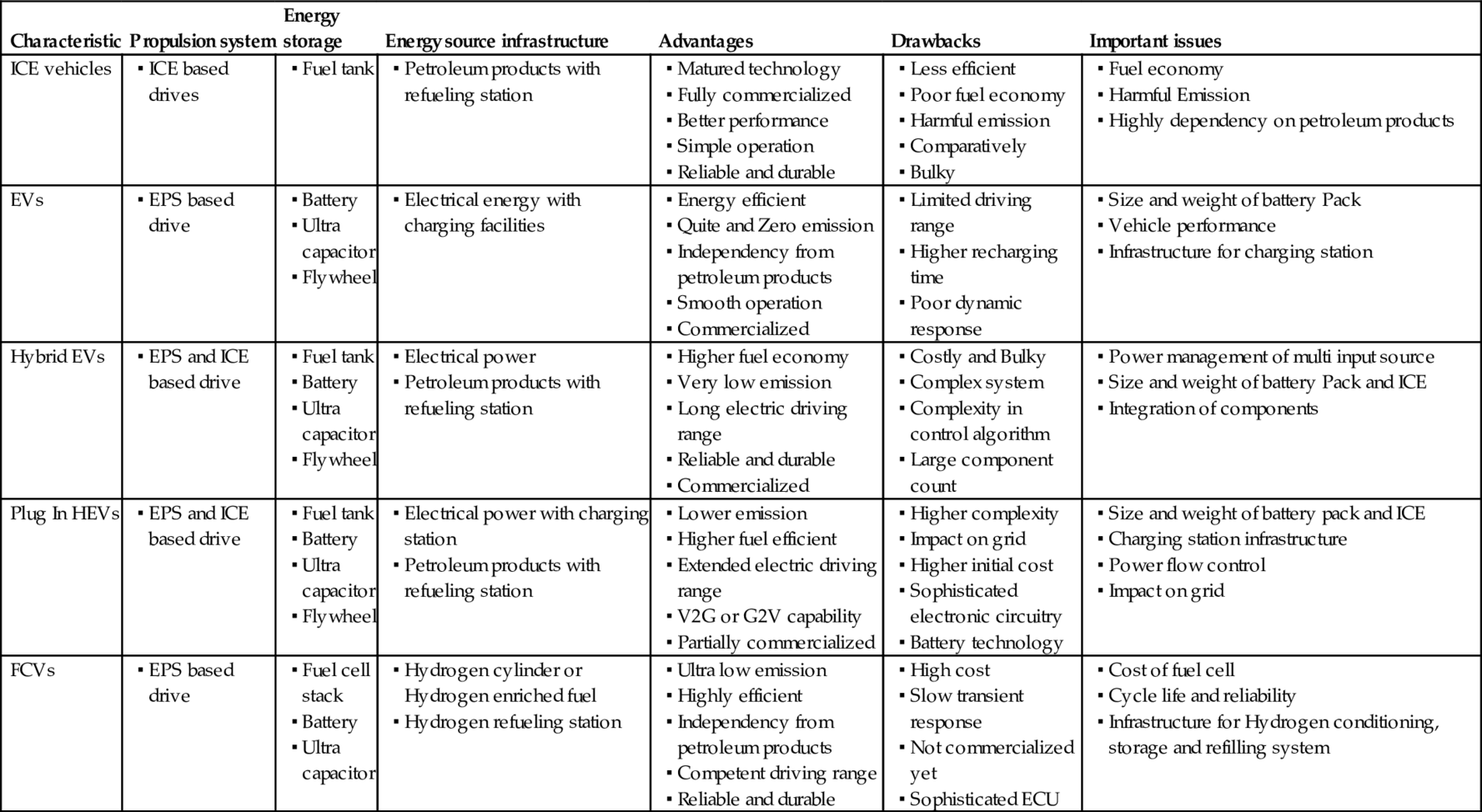
Different types of electrified vehicles have their own capabilities and limitations in terms of emission rate, performance, fuel efficiency, durability, size, weight, cost, safety, and comfort. Among different types of electrified vehicles, HEV is the only one that currently has the potential to compete the ICE vehicle in terms of performance and all driving profiles and offers advantages like extended electric range of operation, good fuel economy, higher efficiency, sufficient onboard power, and better dynamic response [5–10]. However, integration of automobile technology with electric technology adds complexity in controls and makes the HEV system comparatively bulky and costly. At present, HEV technology is rated as a promising technology that is growing rapidly and capturing significant market space at a fast growth rate [7–9]. Plug-in HEVs are currently at the commercialization stage. To be commercially viable, they require good energy policies and infrastructure for charging stations in the near future [13–15]. The efficiency analysis from well to wheels, the concept of V2G and G2V, and the impact of charging station on the grid are the major issues that are being researched for successful commercialization. On the other hand, fuel-cell vehicles, powered by hydrogen, are considered as the future of EVT [27,28]. The different characteristics and issues of ICEV and EVT presented in [8] are revised and summarized in Table 31.2.
Table 31.2
Different characteristics of ICEV/EV/HEV/PHEV/FCV [4]
31.4 Electrical Propulsion System
The sustainability of EVT is relying on maturity, which depends on technological advancement and development of its components such as ESS, PEC, electric motor, and ECU [29,78]. The ESS replaces the fuel tank and fulfills the energy requirement of the electric vehicular system. Basically, ESS provides electric energy that has been processed and utilized by the other components of EPS. The electric motors transform the electric energy into mechanical energy or vice versa, as and when required. It converts electric energy of the ESS into mechanical energy to meet the power demands of the vehicle. The reversible process can also be achieved by regenerative braking, or electric energy can also be generated by electric motor to charge the ESS. The power electronic converters (PECs) are used to modulate power with suitable voltage and current between ESSs and electric motors. For vehicle acceleration, PECs supply required power to the electric motor to achieve the demanded operation. On the other hand, PECs can also be used to utilize the recovered energy of regenerative braking for the charging of ESS. The electronic controllers are composed of sensors, digital processors, and interfacing circuitry to generate the control signals for PECs and other electric and mechanical components.
In order to achieve the vision of sustainable EVT, electric propulsion system should address some important issues such as driving profile, weight and volume of vehicle, reliability and flexibility, packaging and installation, cooling system and maintenance, and all at affordable costs [16,79]. At present, the major challenges of EPS manufactures are to design and implement electric machines and power electronic converters that give better performance and can be more easily integrated for next-generation vehicles.
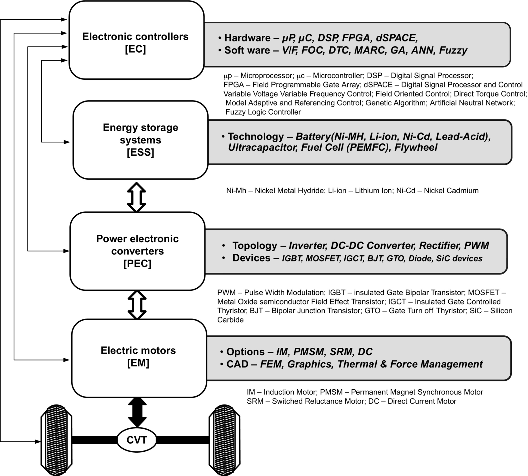
A functional block diagram of electric propulsion system, including the possible types of motors, computer-aided design methodologies, power converter devices/topologies, control hardware, software, and strategies, is shown in Fig. 31.14.
31.4.1 Energy Storage System
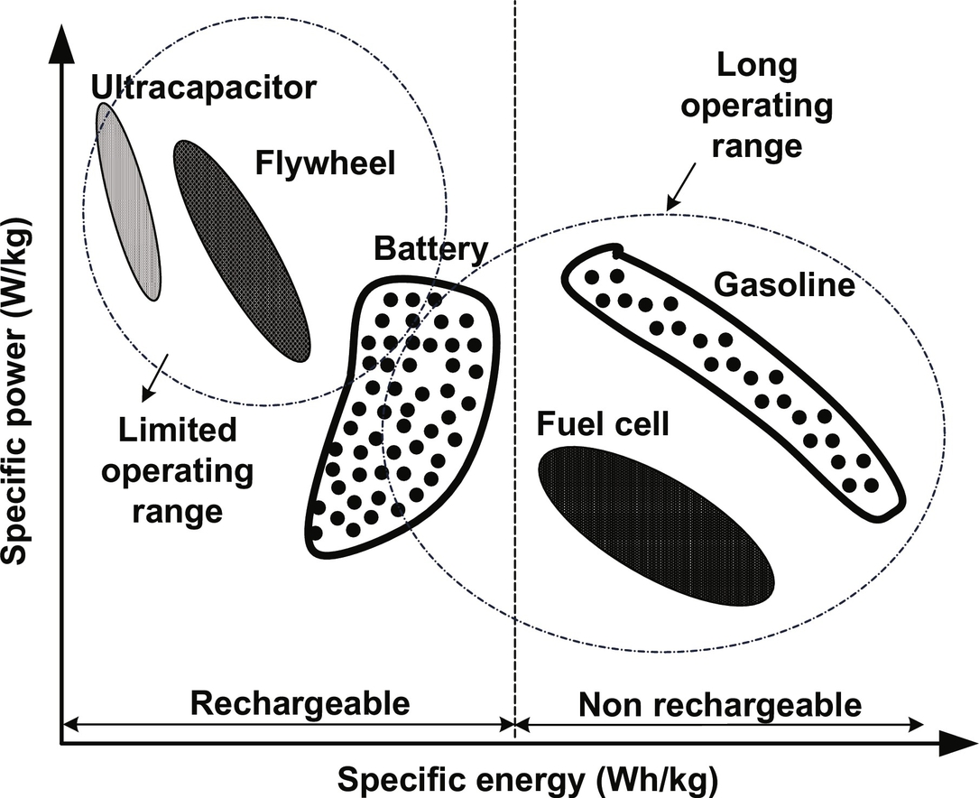
The strength of ESS is an important factor and plays vital role in vehicular electrification [17–20]. Basically, ESS constitutes the source (fuel cell) and onboard energy storage devices that include battery, ultracapacitor, and flywheel. Battery and fuel cell both produce onboard electric energy by means of electrochemical energy conversion; however, a battery stores energy, whereas a fuel cell generates energy. Ultracapacitor relies on electrostatic principle to store energy, and therefore, it has capability to store high specific power rather than energy [18]. Use of flywheel is considered an optional technology for vehicle electrification due to weight and size considerations. The efficiency, fuel economy, and all-electric range (AER) of EVs/HEVs/PHEVs/FCVs are highly dependent on the onboard ESS of the vehicles. The ESS units must be sized so that they store sufficient energy (in kilowatt hours) and provide adequate peak power (in kilowatts) for the vehicle to have a specified acceleration performance and capability to meet appropriate driving cycles [8]. The major factors that affect the design of ESSs for vehicular application include energy density, power densities, life cycle, size, safety, maintenance, and recyclability at projected cost. The basic characteristics of specific power (W/Kg) versus specific energy (Wh/kg) of fuel cell, battery, ultracapacitor, and flywheel in comparison with petroleum-fuel-based ICE are shown in Fig. 31.15.
31.4.1.1 Battery
Battery converts chemical energy into electric energy and vice versa at the time of charging and discharging, respectively. The electrochemical battery is a combination of independent cells that possess all the electrochemical properties. Each cell is capable to store or deliver a significant amount of energy individually or in combination based on their connections [30]. High energy density, modularity, flexibility, and affordability are the factors that guide the battery technology on the road map of vehicle electrification [17]. In EVT, battery stores major onboard energy and contains high energy and power density to meet complete driving cycles of vehicle operation. The basic characteristics of battery for different vehicles are different. High-energy-density batteries are required for EVs, whereas high-power-density battery is required for HEVs and FCVs. For PHEVs, intermediate battery technology is required so that it can match the energy density of an EV battery and the power density of an HEV battery. However, batteries that fulfill the demand of PHEVs are yet to be designed specifically. A suitable battery type for EVT is the lithium-based battery such as lithium ion and lithium polymer and lead-acid and nickel-based battery such as Ni-Cd and Ni-MH [18,30–33].
Among these, lead-acid batteries are used for short-term use because of their low energy density. On the other hand, lithium- and nickel-based batteries are preferred for medium- and long-term use, respectively. However, Ni-Cd and Ni-MH battery technologies are matured, and their potential is fully explored. Therefore, significant improvement and cost reduction in these batteries in the coming years are least expected. The inherent advantages like high energy density, low weight, and low cost of lithium-based batteries invite attraction from automakers. In addition, the potential of lithium-based batteries is still not fully explored, and maturity level is yet to be achieved. Therefore, lithium-based batteries are considered as future's battery technology to power the electrified vehicles. The dominating characteristics and comparison of different battery technologies available in [4] are given in Tables 31.3 and 31.4, respectively.
Table 31.3
Characteristics of different battery technology [4]
| Battery/parameters | Lithium-based | Nickel-based | Lead acid | ||
| Ion | Polymer | Ni-MH | Ni-Cd | ||
| Nominal cell voltage | 3.6 | 3.0 | 1.2 | 1.2 | 2.0 |
| Specific energy (Wh/kg) | 35 | 100–200 | 60 | 40–60 | 35 |
| Energy density (Wh/L) | 70 | 150–350 | 220 | 60–100 | 70 |
| Specific power (W/kg) | ~200 | >200 | 130 | 140–220 | ~200 |
| Power density (W/L) | ~400 | >350 | 475 | 220–350 | ~400 |
| Self-discharge (%/M) | 4–8 | ~1 | 30 | 10–20 | 4–8 |
| Cycle life | 500–1000 | 200–1000 | 300–500 | 300–700 | 250–500 |
| Operating temp (°C) | From −20 to 60 | From 0 to 60 | From −20 to 60 | From −40 to 60 | From −20 to 60 |
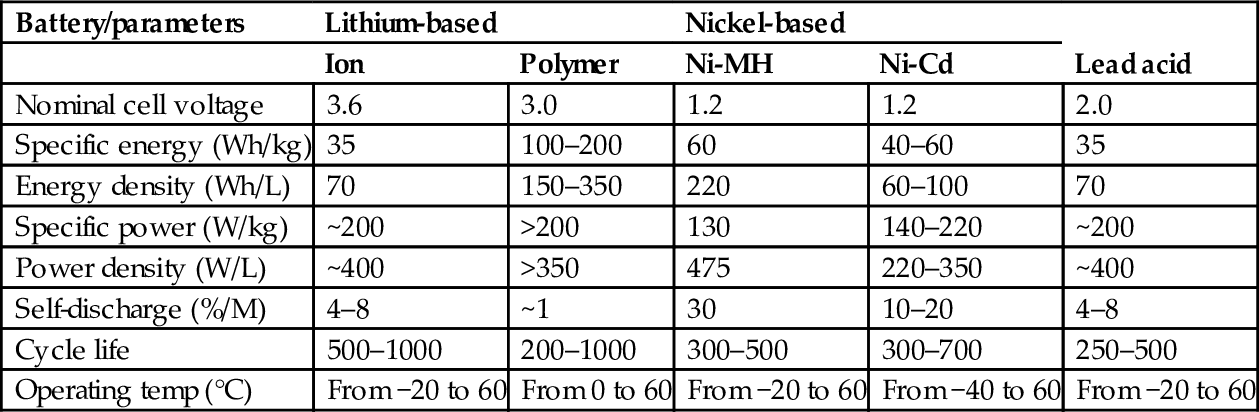
Table 31.4
Comparison of different battery technologies [4]
 |

Source: c. pilot “worldwide rechargeable battery 2007–11/report/pdf.”
31.4.1.2 Ultracapacitor
Ultracapacitor is an electrochemical device that works on electrostatic principle to store energy; therefore, it can be charged/discharged hundreds or thousands of time without degrading the performance [34–36]. Basically, in ultracapacitor, porous carbon electrodes, which offer high surface area (1000 m2gm−1), are impregnated with electrolyte and small charge separation (10 Å) created by the dielectric separator between the electrodes as shown in Fig. 31.16. Appropriate modification in material selection and fabrication brought the ultracapacitor far away from conventional capacitor with very high capacitive (1000–5000 F) density [34]. Ultracapacitor stores energy higher than traditional capacitor but lower than battery, and hence, it can be used for applications, reserved for battery and capacitor.

The detailed comparison is given in Table 31.5. It offers high power density, long cycle life, and efficient operation. Since the rates of charge and discharge are determined by its physical properties, an ultracapacitor can release energy much faster (with more power) than a battery that relies on slow chemical reactions [34–36]. Ultracapacitors have been used for ICE-based vehicle tanks and submarines starting due to its ability of burst power delivery. In EVT, ultracapacitors can be used as primary energy devices for power delivery during starting, acceleration, and hill climbing and for recovery of braking energy during regenerative braking. The combination of ultracapacitor with a battery improves the energy performance of the former with greater energy storage capability of the latter [18]. It can downsize and extend the life of a battery, reducing maintenance and replacement costs. In future, it is expected that ultracapacitor can become a major dominating technology in vehicle electrification; however, desired energy density at reasonable weight and cost is a major concern.
Table 31.5
Different characteristics of battery, capacitor, and ultracapacitor [78]
| Characteristics | Battery | Ultracapacitor | Conventional capacitor |
| Charging time | 1–5 h | 0.3–30 s | 10−3–10−6 s |
| Discharging time | 0.3–3 h | 0.3–30 s | 10−3–10−6 s |
| Energy densities (Wh/kg) | 10–100 | 1–10 | <0.1 |
| Power densities (W/kg) | <1000 | <10,000 | <100,000 |
| Cycle life | 1000–2000 | >500,000 | >500,000 |
| Efficiency (%) | 70–85 | 85–97 | >95 |

The application of ultracapacitor in vehicle electrification is under development, and significant improvement has to be done for achieving maturity and commercialization in mass scale.
31.4.1.3 Fuel Cell
Recent technical advancements in fuel-cell technology have constructed the road map for its application in EVT as onboard energy source [40]. Significant advantages of a fuel cell are eco-friendly, simplicity, continuous power supply, durability, and silent operation along with strict confirmation to emission norms of vehicular systems. In fact, a fuel cell combines the best features of ICE (they can operate as long as fuel is supplied) and batteries (they can produce electricity directly from fuel, without combustion), thereby reducing emissions and noise and increasing the efficiency [41]. A fuel cell is an electrochemical device that uses hydrogen (H2) as fuel and oxygen (O2) from air to produce electricity with water and heat as by-products as shown in Fig. 31.17. To speed up the rate of these reactions, a catalyst such as platinum is used.

In a fuel cell, chemical energy of hydrogen is directly converted into electric power, thus eliminating the intermediate steps of converting fossil fuel to heat and then electric power that enhances efficiency comparatively. The specific energy of a fuel cell is as good as gasoline; however, its specific power is much lesser; therefore, the starting performances of fuel-cell vehicles are very poor. Consequently, to improve the power density and starting performance, battery or ultracapacitor can be used in conjunction with the fuel cell for vehicular application [41,42]. Therefore, it can be said that fuel cells and ultracapacitors are made for each other to lead perfect ESS for automotive. The types of fuel cell and their detailed comparison are presented in [43–45]. Among different fuel-cell technologies presented in [43–45], a PEM fuel cell is promising and is being used as energy source in fuel-cell vehicles. It offers easy start at low temperature, comparatively high power density, simple structure, small size, maintenance-free operation, and ability to operate in hostile environment [44].
31.4.1.4 Flywheel
A flywheel that stores and delivers mechanical energy in the form of rotational kinetic energy has been researched for many decades, but due to heavy weight and high cost, its implementation in vehicular system has been limited. Recent advancement in frictionless magnetic bearing, carbon-fiber composite materials, manufacturing technique, and sophisticated power electronic controllers has accelerated the development of flywheel energy storage system (FESS) [37]. The numerous features of advanced FESS such as higher power density, reliability, efficiency, and higher speed at reduced size made it a potential candidate for ESS in EVT [37–39]. The flywheel rim rotates in an evacuated containment that reduces frictional losses and ensures safety in case of failure.
A flywheel stores energy linear to its mass but square proportional to velocity from supply and delivers it to the load as per the requirements. The stored mechanical energy can be converted to electric energy or vice versa by means of integrated motor/generator set and PEC. Flywheel gets charged by speeding up as it accumulates mechanical energy and discharges by slowing down as it supplies mechanical energy to the EPS. The energy of regenerative braking can be recovered by charging the flywheel, which is further used for battery charging. Modern flywheels can store more energy and power than existing metal hydride or lead-acid batteries of similar weight and volume [38,39]. Unlike battery and ultracapacitor, flywheels are independent of in-depth discharge that improves its life cycle. It spins at a very high speed; therefore, safety, tensile strength of the material, and location of the placement of flywheel in EVT are prime concerns and need to be dealt with properly.
31.4.1.5 Hybrid Energy System
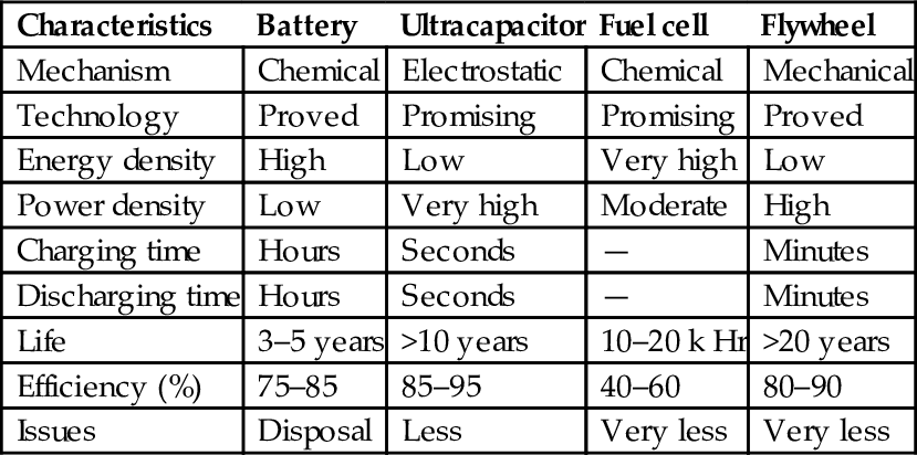
It can be concluded that not only the power and energy densities but also the voltage and current characteristics of different energy systems are different. Therefore, exclusive employment of one of the aforementioned energy sources cannot meet the energy and power demands of vehicle operation for all driving profiles. Compared to ultracapacitors and flywheel, a battery and a fuel cell have much higher specific energy but much lesser specific power as depicted in Table 31.6. Employment of such energy systems alone results higher cost, weight, and volume [46]. However, when these different energy systems are combined, an energy system with high power and high energy density can be obtained. Such kind of energy system is termed as hybrid energy system (HES), where batteries and a fuel cell supply the energy demand and the ultracapacitors and flywheel supply the power demand [46,47]. The combination of energy system can be chosen on the basis of vehicle design, operating profiles, and application. The prime concerns of hybrid energy system formation are their suitable integration, life expectancy, maintenance, cost, durability, and reliability.
Table 31.6
Comparison of different energy source and storage systems [78]
| Characteristics | Battery | Ultracapacitor | Fuel cell | Flywheel |
| Mechanism | Chemical | Electrostatic | Chemical | Mechanical |
| Technology | Proved | Promising | Promising | Proved |
| Energy density | High | Low | Very high | Low |
| Power density | Low | Very high | Moderate | High |
| Charging time | Hours | Seconds | — | Minutes |
| Discharging time | Hours | Seconds | — | Minutes |
| Life | 3–5 years | >10 years | 10–20 k Hr | >20 years |
| Efficiency (%) | 75–85 | 85–95 | 40–60 | 80–90 |
| Issues | Disposal | Less | Very less | Very less |
31.4.2 Electric Motor
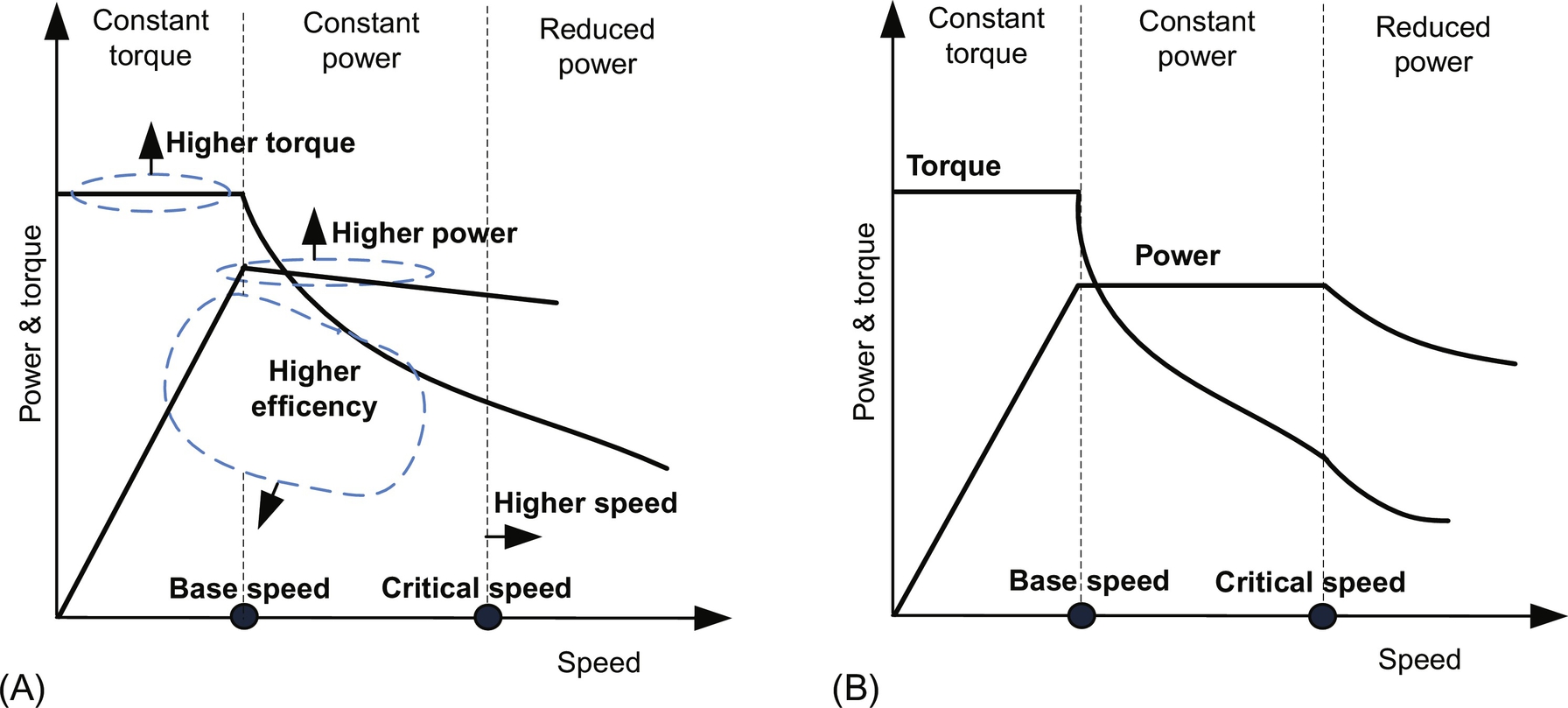
In EVT, the electric motor needs to go through frequent starts and stops, high rate of acceleration, and deceleration, such as low-speed hill climbing and high-speed cruising along with different environmental and hostile conditions. Industrial motors, on the other hand, are usually operated at rated speed under common circumstances [16]. Thus, the electric motors used in EVT cannot be compared with motors being used for industrial processes. The electric motors used for EPS should be able to satisfy some basic characteristic for efficient operation. These characteristics are high torque for starting and low-speed hill climbing operation; high power density for acceleration and high-speed cruising for highway; high efficiency over wide torque and speed range; suitability for regenerative braking; overload capability during certain period of time; and controllability, high reliability, and robustness at affordable costs [48–50]. In addition, fault-tolerant capability, minimum torque ripple, temperature management, and low acoustic noise are other important issues for design consideration [21–24,63,64]. Suitability of electric motor in propulsion application should be strongly approved by torque-speed characteristic as discussed in [56] and illustrated in Fig. 31.18A. Moreover, the standard torque-speed characteristic of EPS is shown in Fig. 31.18B.
The choice of electric motor is the key factor in overall EPS design. A brief classification of the family of electric motor for EPS is summarized in Fig. 31.19. The commonly used electric motors for EPS include dc motor, induction motor, permanent-magnet (PM) motor, and switched reluctance (SR) motor [50–53]. Existing literature indicates that squirrel-cage rotor induction motors and PM motors are best suitable options. Also, SR motors are gaining more popularity and becoming reliable alternative for the future, while use of dc motors is declining gradually.

31.4.2.1 DC Motors
Traditionally, a dc motor has been used prominently for EPS due to its high starting torque and simple speed control. The torque-speed characteristics of dc motor exhibit good compliance for propulsion application; however, the inherent disadvantage of bulky construction, low efficiency, and the presence of mechanical commutators and brushes that aggravate maintenance requirements limit its use in light, high-speed, and maintenance-free vehicle application in hostile conditions [48–51]. Nevertheless, due to simple speed control and technical maturity, dc motors are prominent for low-power EPS. Technological advancements in power electronic converters and switches have helped to replace dc machines with commutatorless motors such as induction motors, PM motors, and SR motors. The commutatorless motors offer some tremendous advantages such as high power density, higher efficiency, and more reliable and maintenance-free operation with wide speed range over the dc motors.
31.4.2.2 Induction Motor
Induction motor (IM)-based propulsion systems are mature and are being extensively accepted as dominating candidate for EPS among various commutatorless motors. The numerous attractive features of IM are simplicity, high reliability, robustness, wide speed range, low maintenance, low torque ripple/noise, low cost, established power electronic converters, and ability to operate in hostile environment [48–53]. The behavior and performance characteristics of dc series motors can also be achieved with induction motor by employing well-matured field-oriented control (FOC) that provides decoupling of torque control from flux control [56]. The dynamic performance of IM can be further improved by applying either vector control or direct torque control (DTC) technique [57]. High-speed operation with extended constant power range of up to 4–5 times the base speed can be achieved by flux weakening, which is one of the desirable requirements for vehicle operation [56], although the high-speed operation and constant power range are limited by its pullout torque.
Apart from the various advantages, there are several disadvantages such as high losses, poor power factor, low efficiency, and low inverter usage. Moreover, its weight and volume are greater for the same power rating as compared with PM motors. These drawbacks of induction motor have been acting as speed bump in the race track. These limitations have been taken into account by the researchers. Efforts are being made to resolve these issues either at design level or by proposing new control schemes and/or converter topologies.
31.4.2.3 Permanent Magnet Motor
Among the available commutatorless motors, only permanent-magnet brushless motors have the capability to compete against the induction motors in EPS [48]. In recent times, PM motors are widely accepted by the leading vehicle manufacturers for designing the existing and upcoming EPS. Generally, PM motors are classified based on supply voltage and current as brushless dc and brushless ac. To maximize the torque density while keeping torque pulsation low, it is preferred to operate a PM machine in BLDC mode for trapezoidal back EMF waveform and in BLAC mode for sinusoidal back EMF waveform [58]. PM motors possess some inherent advantages: PMs excite the field that offers high power density and reduced weight and volume of the motor for a given power rating; due to reduced rotor losses, it offers highly efficient operation; compact packaging provides higher degree of reliability and maintenance-free operation; effective dissipation of heat into atmosphere enables efficient cooling [48–53]. Despite their numerous advantages, PM motors have some limitations such as short constant power region due to limited field weakening capability. In addition, control and management of back EMF at high speed increase size and ratings of PECs, and fault-tolerant capability is an issue. The extended speed range up to 3–4 times the base speed and enhanced efficiency of PM motors can be achieved by applying suitable control algorithms of power converters above the base speed [59]. Important design considerations for PM motors associated with fixed excitation for EPS include torque density, flux weakening capability, overload capability, stator iron losses, rotor eddy-current losses, and demagnetization withstanding capability.
The basic configurations of PM motors are classified based on the location of PMs. In conventional PM motors, PMs either are mounted on rotor surface or buried within the rotor. Surface-mounted PM (SPM) motors are widely used design and uses less magnet, whereas interior PM (IPM) motors use more magnets and offer higher air-gap flux density with higher degree of ruggedness [60]. Therefore, the interior PM motors are exceedingly being preferred for extended speed range and constant power operation over surface PM motors. In conventional PM motors, a compromise has to be made between low-speed torque capability and high-speed power capability. In order to overcome this problem, the concept of hybrid PM motor and field excitation technique has been adopted [49]. Conceptually, hybrid PM motor is either a combination of PM motor and reluctance motor or an inclusion of additional field winding that limits air-gap field. Thus, the hybrid PM motors enhance the overall operational efficiency and offer wide speed, constant power operation with more complex structures. Availability, cost, and supply issues with rare-earth PMs may affect their wide applications in EPS.
31.4.2.4 Switched Reluctance Motor
SR motor is gaining more and more attention for EPS in vehicular application. An SR motor offers tremendous potential for vehicular application especially for HEVs and FCVs [61,62]. The remarkable features of SR motors are the following: rotor without magnet and windings offers simple and robust construction that is desirable for very-high-speed and high-temperature operation; excellent torque-speed characteristics; fault-tolerant capability; and constant power region that can be extended up to 3–7 times, smooth and hazard-free operation [48–53]. Limitations of SR motors include high acoustic noise, vibrations, high torque ripple, complex control mechanism, and requirement of special converter topology. Although the cost of SR motors is relatively high, their mass production is expected to render them as cost-effective as induction motors. All the advantages are prominent for vehicular application, whereas the disadvantages are needed to be taken care properly to have feasible SR motor-based EPS.
Comparison of different motors based on desirable characteristic for EPS is shown in Table 31.7. The suitability of particular motor at particular characteristic is rated in the scale of 1–5 relatively. The point 5 indicates the higher attributes, whereas point 1 shows the poor attributes. This comparison is indicative and measured relatively on the basis of existing literature; however, it may vary with several factors like the design consideration of motor's type, placement of motor (in wheel or out of wheel), material used for magnet, core and laminations, relevant power electronics converter, and their control algorithms [21]. The main purpose of Table 31.7 is to bring out the motor technology with higher attributes to vehicular application.
Table 31.7
Comparative analysis of different electric motors used in EPS [78]
| Characteristic | dc | IM | PMSM | SRM |
| Controllability | 5 | 5 | 4 | 3 |
| Size and weight | 3 | 4 | 4.5 | 4 |
| Robustness | 3.5 | 5 | 4 | 4.5 |
| Reliability | 3 | 5 | 4 | 4.5 |
| Power density | 3 | 4 | 5 | 3.5 |
| Efficiency | 3 | 4 | 5 | 4.5 |
| Speed range | 2.5 | 4 | 5 | 5 |
| Life time | 3.5 | 5 | 4 | 4.5 |
| Torque density | 3 | 3.5 | 5 | 4 |
| Technical maturity | 5 | 4.5 | 4 | 3.5 |
| Cost | 3.5 | 5 | 3 | 4 |
| Overload capability | 3 | 4 | 4.5 | 4 |
| Torque ripple/noise | 3.5 | 4.5 | 4 | 3 |
| Manufacturability | 3 | 5 | 3 | 4 |
| Improvability | 2.5 | 3 | 4.5 | 5 |

31.4.3 Power Electronics Converters for EVT
For sustainable EVT, there is a need of highly reliable, flexible, and fault-tolerant electric power processing system on board to deliver high quality of power, as per vehicle demands [24]. At present, this responsibility has been taken care by the available PEC that includes dc/dc converters, rectifiers (dc/ac), inverters (ac/dc), and battery charger that is composed of ac/dc and dc/dc converters.
Individually or combination of these converters can be taken to serve the purpose of onboard power processing; however, operation of each PEC is entirely different from the other. Conceptually, PECs perform some of the critical tasks like ON/OFF switching of various actuators, valves, and equipments; power conditioning and voltage/current modulation to create compatibility among the sources; traction motors; and auxiliary loads like air conditioner, head lamp, power steering, power window, etc. [63]. PECs not only serve the purpose of converting electric power from one form to another (dc/dc and dc/ac) but also help to step up or step down the system voltage level on board.
These PECs are composed of power electronic devices that play significant role and are evolving rapidly. The selection of PEC devices for EV propulsion is generally based on the requirements of the voltage rating, current rating, switching frequency, power loss, and dynamic characteristic of the system [63]. The voltage rating depends on the battery nominal voltage, maximum voltage during charging, and regenerative braking. The current rating depends on the motor peak power rating and number of devices connected in parallel. Furthermore, the switching frequency should be high enough to reduce the noise, filter size, and EMI problem with good dynamic characteristics. The device protection, packaging, reliability, and cost should also be considered while choosing particular device. Among the available power devices, the GTO, BJT, MOSFET, IGBT, and MCT are particularly suitable for EV propulsion [38]. Some of their operating characteristics as presented in [74] are given in Table 31.8. At present, the most attractive and suitable device for EVT is IGBT, which possesses high-speed characteristics of a MOSFET with the high-conductivity characteristic of a BJT. In the near future, the wideband gap (WBG) devices like SiC and GaN will be the most favorable candidate for EPS because they provide high-temperature operation, high-power-handling capability, superior dynamic characteristic, low switching losses, and high reliability [74].
Table 31.8
Power semiconductor devices for EPS [74]
| Component | Semiconductor devices | Voltage rating (volt) | Current rating (amp) | Power rating (kW) | Switching frequency (kHz) |
| Inverter/rectifier for EPS | IGBTs/diodes | 600–1200 | 100–600 | 20–100 | 5–30 |
| dc/dc converter for EPS | IGBTs/diodes | 600–1200 | 100–600 | 20–100 | 5–30 |
| Inverter/rectifier for auxiliary loads | IGBTs/MOS-FET/diodes | 600–900 | 15–60 | 2–4 | 5–50 |
| dc/dc converter for low-power loads | MOSFET/diodes | 400–600 | 10–40 | 1–2 | 50–200 |

In the last decade, significant advancement in converter topologies dealing with battery charger, voltage-source inverter for motor drives, and bidirectional dc/dc converter for ESS integration has been made. Regardless of this topological advancement, still conventional PEC topologies are being used in modern electrified vehicles. Therefore, PECs for EVT can be broadly classified as shown in Fig. 31.20. The classification of the PECs is done based on their basic operation rather than topological advancement.

The current trends and future status of EM, PEC, and EPS based on essential characteristics of vehicle application are summarized in Table 31.9.
Table 31.9
Present and future status of EM, PEC, and EPS [16]
| Characteristic | Electric motors | Power electronic converter | Electric propulsion system | |||||||||
| 2010 | 2013 | 2015 | 2020 | 2010 | 2013 | 2015 | 2020 | 2010 | 2013 | 2015 | 2020 | |
| Power density (kW/L) | 3.7 | 4.8 | 5 | 5.7 | 8.7 | 10.2 | 12 | 13.4 | 1.06 | 1.15 | 1.2 | 1.4 |
| Specific power (kW/kg) | 1.2 | 1.3 | 1.3 | 1.6 | 10.8 | 11.5 | 12 | 14.1 | 2.6 | 3.1 | 3.5 | 4.0 |
| Efficiency (%) | 90 | 91 | 92 | 93 | 91 | 92 | 94 | 97 | 90 | 91 | 93 | 95 |
| Cost ($/kW) | 11.1 | 9.5 | 7 | 4.7 | 7.9 | 6.5 | 5 | 3.3 | 19 | 16 | 12 | 8 |

31.4.3.1 PEC Configuration for EPS
PECs are controlling, managing, and optimizing the power flow among energy sources and vehicle loads, and hence, they are considered as the heart of EPS, whereas EPS is the heart of EVT. The architecture of modern EPS for EVT with interconnection among electric power system, ESS, propulsion system, and control and protection system is shown in Fig. 31.21. The main elements for the power processing and conversion comprise an ac/dc charger, a bidirectional dc/dc converter, a dc/ac inverter, and a digital controller.

Charging from utility grid inevitably needs a battery charger with power factor correction (PFC). The bidirectional dc/dc converter with a proper charging-discharging profile is required to transfer energy between the ESS and the propulsion system [73]. The plug-in charger is usually composed of ac/dc rectifier and dc/dc converter. The bidirectional dc/dc converter is placed between the add-on battery and the high-voltage bus of the HEV. The digital controller is in charge of the control and monitoring of the ac/dc charger, bidirectional dc/dc converter, dc/ac inverter for propulsion, battery state of charge (SOC), and communication with external systems. Three voltage sources, that is, ac outlet voltage Vac, battery voltage Vbatt, and input to the propulsion inverter Vo, are shown in Fig. 31.21. These voltages are might be different from input/output voltage magnitude in each converter stage. This variation in voltage magnitude governs the operating modes and switching strategy of the converters under the supervision of digital controller.
The PECs contributing weight and volume of EPS are inverter, onboard charger, and bidirectional dc/dc converter. The main attention is being focused on bidirectional dc/dc converter for power-flow optimization [70]. Apart from dc/dc converter, innovative efforts are also directed toward inverters that drive the traction motors and supply the auxiliary loads of electrified vehicle in desired manner. The selection of inverter should be done based on the topology, power rating, type of motors, and the packaging methods [71]. Despite of significant topological advancement in multilevel inverters, as of now, the conventional two-level voltage-source PWM inverter is the most popular topology used in almost all the commercial electrified vehicles.
In EPS, two popular configurations are used to interface the ESS with propulsion inverter motor: (i) A high-voltage ESS is directly connected to propulsion inverter motor; (ii) a bidirectional dc/dc converter is placed between low-voltage ESS and propulsion inverter-motor drive [24]. In the first configuration, battery voltage level should match with propulsion inverter dc-link voltage level as shown in Fig. 31.22. This imposes certain constraints over the design and optimization of battery, inverter, and motor [24]. In the second configuration, a bidirectional dc/dc converter is placed between low-voltage ESS and high-voltage dc link of propulsion inverter motor as shown in Fig. 31.23. Inclusion of dc/dc converter increases overall component count but offers several advantages over the first configuration. It boosts voltage level of ESS to match the rated voltage of propulsion inverter dc link. It provides regulated bidirectional power flow between ESS and motor drive, which assists rapid acceleration and recovers energy to charge the battery during deceleration and regenerative braking. It not only offers significant reduction in weight, size, and cost of ESS but also gives space and flexibility in inverter control and motor design [24]. Another most important aspect of the inclusion of dc/dc converter is to recover the energy during regenerative braking that can be further utilized to recharge the battery or storage unit.


Addition of bidirectional dc/dc converter imposes certain disadvantages such as multistage power conversion, increased cost, power losses, integration, and control complexity. It also raises concern about size and cost of power switches and passive components. In addition, the reliability issues due to the integration of additional components must be taken into account properly. However, the role of bidirectional dc/dc converter is very significant especially in terms of better utilization of onboard energy sources, power management, dynamic performance, flexibility, system optimization, and reduction of weight and cost [64].
31.4.3.2 PEC Configurations for Electrified Vehicle
PEC integration for EPS that completely replaces ICE-based propulsion system is shown in Fig. 31.24. In conventional configuration of EVs propulsion system, a battery bank is directly connected to propulsion inverter that converts dc voltage into three-phase variable ac voltage. This configuration is applicable to the system where battery bank is sufficiently large to match with the voltage of propulsion inverter-motor drives as discussed in previous section. In the second configuration of BEV propulsion system, a bidirectional dc/dc converter is connected in between battery bank and propulsion motor as shown in Fig. 31.24A. Inclusion of bidirectional dc/dc converter increases flexibility and control in power flow and management from battery bank to propulsion inverter. It offers better utilization of battery bank and extends life of battery with controlled charging and discharging. It also helps to recover energy during regenerative braking. A battery charger is connected to battery bank to charge the battery from ac outlet. BEVs practically replace the ICE and the various mechanical systems with electric system.

It is well-established fact that the traditional rechargeable batteries are the main source of energy though they are heavy and expensive to replace and hence acting as a bottleneck of the BEV technology. In addition to traditional batteries like lead-acid, nickel-metal hydride (Ni-MH), and nickel-cadmium (Ni-Cd), there are advanced technologies like lithium-polymer (Li-polymer) and lithium-ion (Li-ion) batteries. Despite the popularity of these advanced batteries in portable electronic applications, they fail to keep same reputation for use in BEVs [22]. Consequently, the vehicle manufacturers are cutting down the production of BEV and shifting toward development on HEVs and FCVs.
The PEC for HEVs as shown in Fig. 31.24B consists of an ac/dc converter for converting the alternator ac output voltage into dc voltage for charging the batteries, an inverter for dc/ac conversion to power the propulsion motor, and a bidirectional dc/dc converter for charging the battery and maintaining bidirectional power flow. In addition to this, a low-voltage dc/dc converter is also connected to the battery bank to supply power to low-voltage ancillary loads of the vehicles. Furthermore, an electric air-conditioning unit, pump, and compressor units need an inverter and associated control systems [22].
The PEC configuration of plug-in HEV shown in Fig. 31.24C is similar to HEV with the charger facility to charge the battery bank from utility grid. The high-energy battery bank must be able to store enough electric energy from external charging and from regenerative braking and must be able to supply the stored electric energy to a propulsion inverter-motor system [23]. ac outlet charging should inevitably need a battery charger that is composed of a PFC-integrated ac-dc converter with a proper voltage-current profile for high-energy battery bank. A bidirectional dc-dc converter and charge-discharge profile is also necessary so as to transfer energy between the battery and the propulsion motor system as per requirement [23].
The main task of the fuel-cell propulsion system is converting the fuel-cell stack power output into a usable power for different electric and mechanical loads. Furthermore, the objective is to realize the full potential of the onboard fuel-cell stack by implementing efficient PEC in cost-effective manner. The primary power conversion would be used for three-phase ac output with variable voltage and variable frequency for the propulsion motor of the vehicle [80]. It is important to note that a high-peak-to-average power ratio is generally demanded from the PEC. If there is no ESS, the fuel-cell stack also needs to maintain the above critical power ratio to a maximum that increases size and volume of fuel-cell stack. Secondary power conversion is required for 12 or 42 V auxiliaries and for other loads such as air conditioning, pump, and power steering [80].
The different configuration of fuel-cell-based propulsion system for passenger car is shown in Fig. 31.25. The output voltage of the fuel-cell stack is first conditioned and processed to be compatible with the ESS voltage and propulsion motor using a dc/dc converter. The type of dc/dc converter depends on the voltage level of a fuel cell and ESS. A propulsion inverter is used to convert the dc voltage into modulating ac voltage at variable frequency to drive the propulsion motor under different torque and speed. The electronic controller unit (ECU) sends control signals to regulate the power output of the fuel cell, the dc/dc converter, and the dc/ac inverter based on the feedback signals of speed and torque and driver commands [80].

To begin with fuel-cell vehicle, a simplest configuration of a fuel cell is directly connected to propulsion motor through dc/ac converter. This configuration is applicable to the system only if the fuel-cell stack can produce a voltage level that is suitable for the propulsion inverter motor. However, this configuration is not preferred in general; hence, a unidirectional dc/dc boost converter is connected in between the fuel-cell stack and propulsion inverter as shown in Fig. 31.25A. The purpose of the dc/dc converter is to condition the fuel-cell power and raise the voltage level to match with the dc-link voltage. Typically, dc-link voltage in the range of 300–400 V is favorable for power levels up to about 100 kW [23]. A diode is connected in series with the output of the fuel-cell stack to prevent it from overload, getting short-circuited at output terminal, and to prevent current flowing back into fuel-cell stack [22]. Further, an additional low-voltage dc/dc buck converter is connected to supply the power to ancillary loads. Unlike the ICE-driven alternator, a fuel cell can produce power on board for different ancillary electric loads of vehicles that can eliminate the need of an alternator.
Fig. 31.25B shows the modification to system shown in Fig. 31.25A, with a low-voltage ESS connected through bidirectional dc-dc converter that performs the crucial task of power management and control. Generally, fuel cells are very efficient over particular load range but exhibit poor efficiency under light load condition and poor dynamic response during transient [24]. Therefore, integration of battery and ultracapacitor with a fuel cell makes it sustainable HES onboard for vehicular application. The ESS provides an input power to the propulsion inverter during warm-up time of the fuel cell. Once the fuel cell starts providing the required power, the ESS is disconnected, and the system can completely run on the fuel cell. The ESS system also provides power during transient conditions, to support the fuel cell, which improves the dynamic response and load leveling of overall system [80].
The fuel-cell propulsion system wins over ICE propulsion system on higher fuel conversion efficiency and fuel flexibility, emits practically no toxic pollutants, and reduces CO2 emission drastically. However, a fuel-cell system designed for vehicular propulsion system should have weight, volume, power density, start-up, and a transient response similar to present-day ICE-based propulsion system [23].
31.4.3.3 PEC Configurations for ESS and HES
ESS whether battery and/or ultracapacitor is employed to reduce the cost and improve the performance of electrified vehicles [18]. The voltage level, V-I characteristics, and dynamic response of the ESS are normally different from the primary energy sources (ICE or fuel cell). Thus, a PEC needs to be incorporated to manage and control the power flow in overall vehicle system, which is a key component for achieving better fuel efficiency and dynamic performance [68,69]. For HES, storage element is an essential requirement to act as an energy buffer during transients in the system, to improve the dynamics of the overall system. Also, the storage element compensates the mismatch in power, between the source and load. Therefore, the choice of source combinations, such as battery/ultracapacitor or fuel cell/battery, fuel cell/ultracapacitor, and fuel cell/battery/ultracapacitor, is primarily governed by characteristics of the primary source and operating condition of the load [40,41].
In a fuel cell, the amount of power delivered depends on hydrogen pressure and slow chemical reaction results in poor dynamic response. Therefore, it should be combined with battery or ultracapacitor to achieve sustainable HES [40]. For example, a fuel cell and an ultracapacitor are combined together to constitute a portable HES that can meet different energy and power requirements as necessitated by different driving profiles of vehicle [41]. During acceleration, bulk amount of power has to be released to develop sufficient thrust. This responsibility can be well taken care by ultracapacitor as it can deliver power quickly. Similarly, a fuel cell can support to extend all-electric driving range of the vehicles, by supplying constant power, which in turn enhances durability and life span of the fuel-cell membrane [44].
In HEV, it is desired for the energy system to have high power density and high energy density to cater the sudden changes in the load demand [9]. Moreover, applications that require instantaneous power input and output delivery typically find batteries suffering from frequent charge and discharge cycle, which have an adverse effect on battery life. For such systems, it is crucial to have an additional storage system that is much better and robust in handling surge current. Here, the basic idea of HES is to combine battery and ultracapacitor to achieve a better performance than the latter system. Thus, an ideal source for EVT would be the combination of both the storage sources [18]. Also, the hybridization of battery and ultracapacitor offers much better utilization of energy recovered during regenerative braking.
HES demands suitable PEC to incorporate different energy sources and manages power flow among different sources and vehicle loads [18]. Therefore, investigation on PEC for HES is crucial task in EPS design for achieving optimal balance among efficiency, performance, durability, and reliability of system [63]. In HES, a dc/dc converter is the key constituent that provides compatible interfacing and integration of energy sources [64]. Beside output voltage regulation, a well-designed dc/dc converter can also control and manage power flow through different components. Therefore, selection and design considerations of dc/dc converters are important aspect in ESS. Apart from dc/dc converter, multiple-input dc/dc converter and multiphase interleaved converters are also employed for better energy diversification and utilization of the onboard HES [66,67]. Several topologies for HES configuration for EVT have been proposed in [68–70] to improve fuel efficiency and dynamic performance that range from simple to complex circuits. On the basis of the use of dc/dc converter, HES can be classified into two categories: passive configuration and active configuration.
Passive configuration
Passive configuration [33] is the simplest method of combining battery and ultracapacitor (UC) bank together as shown in Fig. 31.26A, where battery and ultracapacitor are connected together in parallel without any dc/dc converters. In this method, since the two sources are connected in parallel, battery voltage, ultracapacitor voltage, and dc-link voltage should be maintained at the same level, and ultracapacitor essentially acts as filter. This configuration is easy to implement and eliminates need of expensive PEC and peripheral circuitry. However, major problem with this configuration is inefficient utilization of stored energy in ultracapacitor and battery.
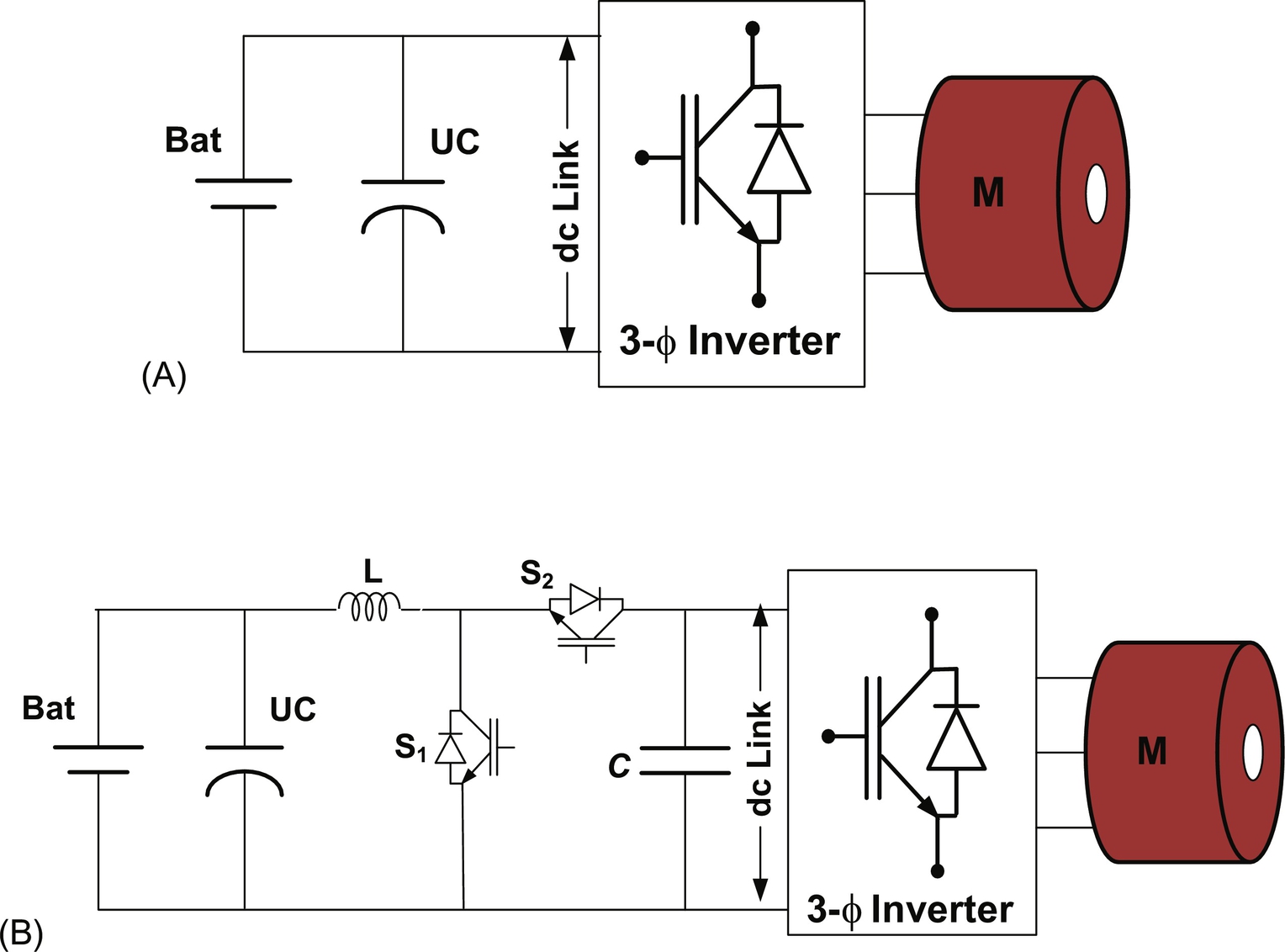
To improve power flow and its proper utilization, a bidirectional dc/dc converter interfaces the parallel-connected ultracapacitor and battery with the dc link as shown in Fig. 31.26B. Despite wide voltage variation across ultracapacitor terminals, the dc-link voltage remains constant due to the regulation of the dc/dc converter. However, in this configuration, the battery voltage is always the same with the ultracapacitor voltage due to the lack of interfacing control between the battery and the ultracapacitor [18]. The battery current must charge the ultracapacitor and provide power to the load side as well.
Active configuration of battery/ultra capacitor
Conventional active methods use one or multiple full-size dc/dc converters to hybridize the battery and ultracapacitor to the dc link. In this case, full size refers to the fact that the dc/dc converter forms the sole path for the flow of energy in the device. The UC/battery configuration as shown in Fig. 31.27A proposed in [31] is the most studied and researched HES. By using a bidirectional dc/dc converter to interface the ultracapacitor, the voltage of ultracapacitor can be used in a wide range. However, the bidirectional converter needs to be of a larger size in order to handle the power of the ultracapacitor. The battery is connected directly to the dc link; as a result, the dc-link voltage cannot be varied. By swapping the positions of the battery and ultracapacitor in the ultracapacitor/battery configuration, we get the battery/ultracapacitor configuration as discussed in [68] and shown in Fig. 31.27B. In this configuration, the voltage of the battery can be maintained lower or higher than the ultracapacitor voltage. The ultracapacitor is connected in parallel with the dc link directly working as a low-pass filter. The control strategy applied to this configuration allows the dc-link voltage to vary within a range such that the ultracapacitor energy can be utilized more efficiently. However, in standard practice to achieve efficient HES, it is preferred that fast-response components are connected with high-power-density system whereas slow response devices are connected to high-energy-density system.

Cascaded configuration
To make a better working range of the ultracapacitor of the battery/ultracapacitor configuration, another bidirectional dc/dc converter is added between the ultracapacitor bank and the dc link, as shown in Fig. 31.28. This forms a cascaded configuration where two dc/dc converters are connected in series. In this configuration, a smaller size battery can be used with lower voltage level, which can be boosted up to a higher voltage level, to reduce the cost. In addition, the battery current can more efficiently be controlled compared with the passive configuration. Due to the existence of the boost converter, the battery current is smoothened, and the stress on the battery is reduced [18]. The battery supplies average power to the load, whereas the ultracapacitor delivers instantaneous power charge and gets charged quickly by recovering energy during regeneration. The drawback of this topology is that the battery can be charged neither by braking energy nor by the ultracapacitor due to the unidirectional boost converter [18]. However, the possibility of battery charging can be explored by replacing unidirectional dc/dc converter with a bidirectional dc/dc converter.
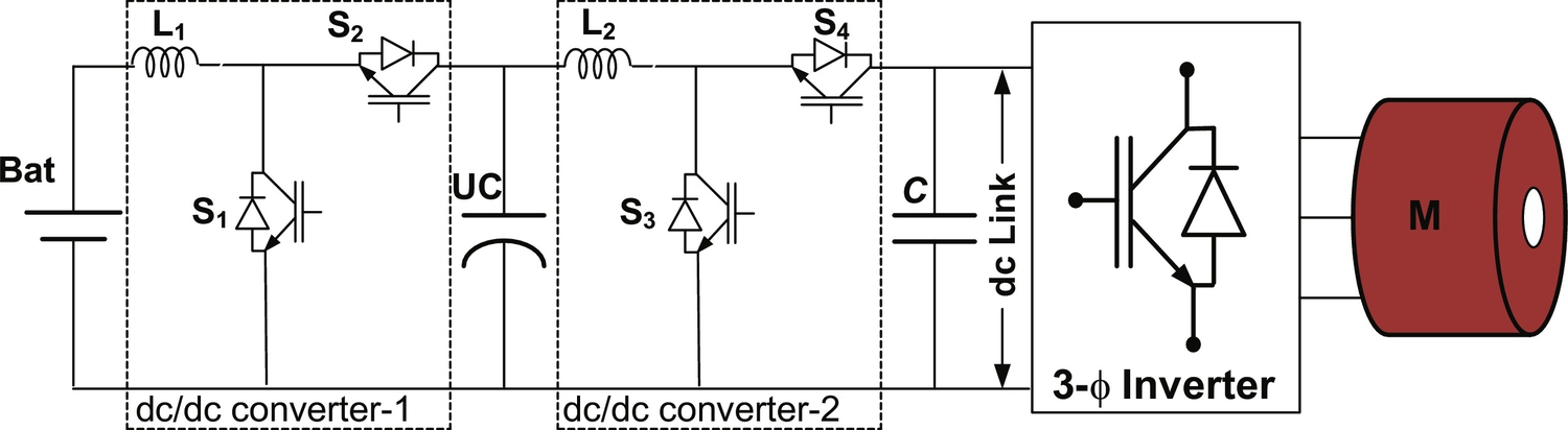
Parallel configuration
Instead of cascaded connection of the two converters, parallel configurations of battery/ultracapacitor are also used as shown in Fig. 31.29 proposed in [66]. The battery bank and the ultracapacitor are connected to the dc link in parallel through bidirectional dc/dc converter. In this configuration, both the battery and the ultracapacitor present a lower voltage level than the dc-link voltage. The voltage of the ultracapacitor can vary in a wide range so that capacitor is fully used. The voltages of the battery and the ultracapacitor will be boosted up when the propulsion system demands power and bucked down under recharging conditions. Power-flow directions in/out of the battery and the ultracapacitor can separately be controlled, allowing flexibility for power management [18]. However, if two full-sized dc/dc converters are integrated in parallel, the cost, size, and complexity of control increase.

Multiple input configuration
As discussed in previous section, multiple-converter configuration is expensive because it requires two full-size bidirectional converters to interface both battery and ultracapacitor. Therefore, multiple-input converter (MIC) topologies [81–84] are proposed in order to reduce the cost of the overall system. The configurations of the MIC are shown in Figs. 31.30 and 31.31. MIC is a converter that can combine different energy sources with a single stage of power conversion. It offers simplicity, flexibility, and compact design and reduces the cost and control complexity of the system [82–84]. In the multiple-input bidirectional converter shown in Fig. 31.30, both the battery and the ultracapacitor are connected to one common inductor by parallel switches [81]. Each switch is paired with a diode, which is designed to avoid short circuit between the battery and the ultracapacitor. In parallel-connected switch, the higher-voltage-source cell will be dominating, which needs time multiplexing switching. The second approach is to form a pulsating voltage-source cell (PVSC) of the sources and connect these PVSC in series as shown in Fig. 31.31 and proposed in [82]. In series configuration of MIC, voltage magnitude of battery and ultracapacitor can be asymmetrical, and each of the sources can deliver power individually and simultaneously. Both input voltages are less than the dc-link voltage; thus, the converter works in boost mode when input sources supply energy to drive load and in buck mode for recovering regenerative braking energy to recharge the battery and the ultracapacitor [81]. Only one inductor is needed, even if more inputs are added into the system. However, the controlling strategy and power-flow management of the system are relatively complex.
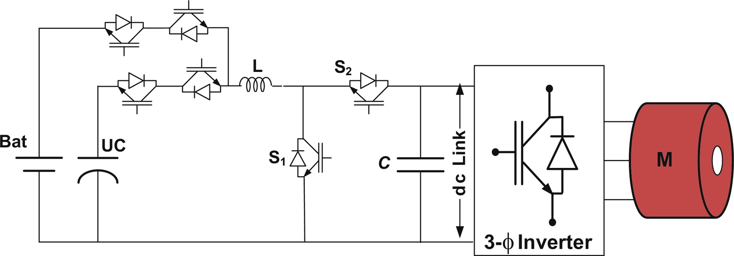
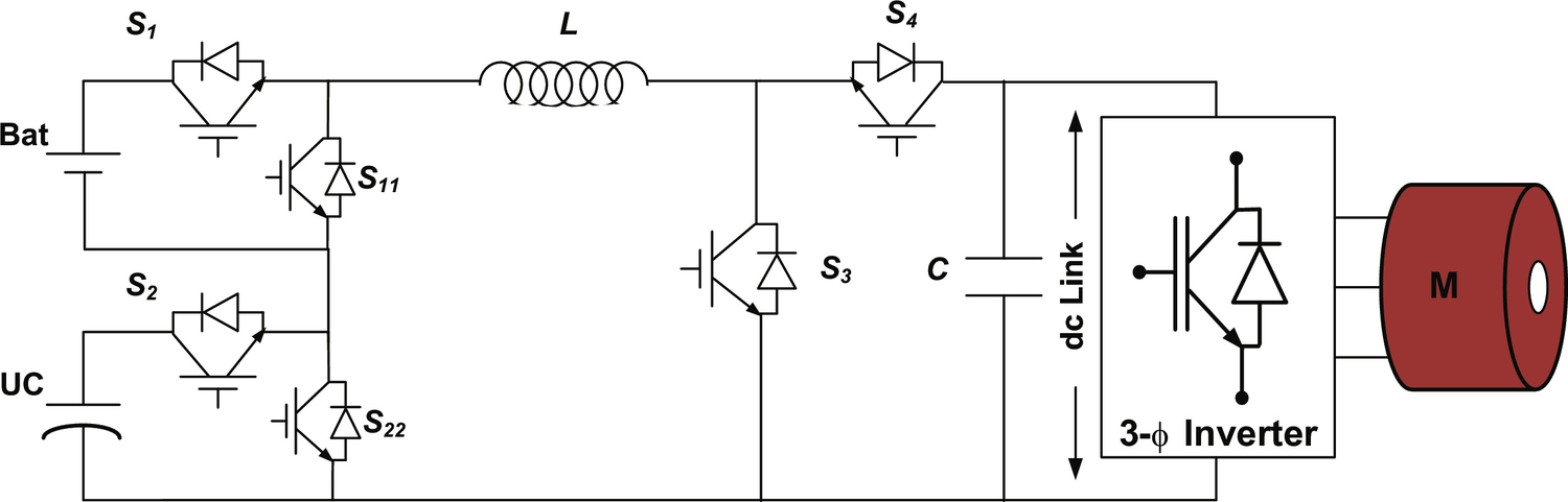
As discussed in parallel configuration, in HES, each energy source is connected together through separate single-input dc/dc converter (SIC), and their outputs are connected in parallel to a common dc bus as shown in Fig. 31.32. In conventional configuration paralleling, the whole system including energy sources offers good solution to obtain high degree of availability [76,83,84]. However, such configurations are costly, bulky, and relatively complex in design and reduce overall efficiency and flexibility and increase control complexity of the system. If costs and availability are being considered, then the single-input converters can be successfully replaced by a single multiple-input converter as shown in Fig. 31.33.

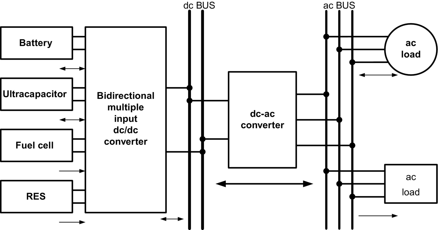
The conventional structure of interfacing multiple energy sources in multiple power stages can be successfully replaced by a single MIC that integrates multiple energy sources with a single stage of power conversion. In this structure, the system voltage is regulated, and the power flow among the energy sources, storage devices, and load can be controlled optimally and centrally. It eliminates the need for redundant power stages of the conventional structure and thus achieves reduced parts count [83]. MICs have advantages of easy power management, efficient thermal management, better utilization of available input sources, and centralized control compared with a conventional structure. The overall system efficiency is increased due to the reduction of the conversion stages, redundant passive elements, power switches, and hence their associated losses. The disadvantage of the MIC configuration is that the output stage of a MIC can act as a single point of failure. However, a MIC with modular component can compensate for this drawback by reducing the mean downtime (MDT) of the system [67].
In HEV, as shown in Fig. 31.34, where the combination of battery and ultracapacitor is preferred, battery supplies constant power, whereas additional power demand by the load during start-up and acceleration is delivered by the ultracapacitor while maintaining dc-link voltage constant. The amount of power drawn from the battery relies on the state of charge (SOC) of the battery; thus, for change in power drawn from the battery, power delivered by the ultracapacitors should also be changed. Thus, effective power sharing can be achieved by MICs depending on the control strategies and operating mode. This modulation of power between battery and ultracapacitor is not possible in conventional structure because both the sources have to supply constant power to regulate the output dc-link voltage.
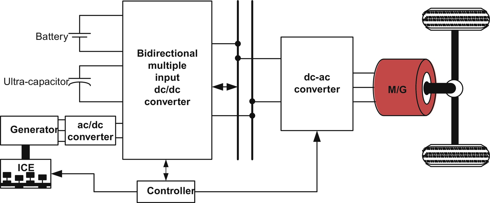
MIC structure has an explicit advantage over the conventional structure in terms of total component count and conversion stages used due to mutual sharing of system components. As a result, compact design and improved system efficiency can be achieved. Comparison of these two structures given in Table 31.10 shows that the MIC structure is promising alternatives in vehicular application to interface multiple sources on board.
Table 31.10
Comparison of SIC and MIC structure [83]
| Characteristics | SIC structure | MIC structure |
| Common dc bus | Yes | No |
| Conversion step | Multiple | Single |
| Control scheme | Individual control | Centralized control |
| Power-flow management | Complicated and slow | Simple and fast |
| Transformer (isolated) | Multiple | Single multiwinding |
| Implementation effort | High | Low |
| Component count | High | Low |
| Flexibility | Low | High |
| Cost and volume | High | Low |
31.4.3.4 PEC Configurations for Battery Charger
PEC configuration for battery chargers plays a critical role in the sustainable development of BEVs/PHEVs. The challenge of transforming BEVs/PHEVs from concept to reality is to make it safe, convenient, and affordable for consumers to charge batteries [63]. In order to improve convenience and increase charging efficiency, a number of charging schemes have been proposed as house charging, solar charging station, park and charge (PAC), move and charge (MAC), and regenerative charging as shown in Fig. 31.35. A battery charger composed of several PECs should be reliable and efficient with high power delivery capacity at low cost and weight. Its operation depends on power electronics component, switching strategies, and control algorithms. A BEV/PHEV charger must ensure the operation at unity power factor or close to unity power factor to draw maximum amount of real power from utility grid with less distortion in current to minimize the power quality impact on grid. The battery charger should be designed according to IEEE-1547, SAE-J2894, and similar standards such that the amount of harmonic and dc current injected into the utility grid must be controlled within the preset limit.

A variety of PEC configurations and control methods have been developed as BEVs/PHEVs battery chargers, which includes single-stage and multistage power conversion. Single-stage conversion (ac/dc) configuration suffers with large low-frequency ripple in the output current, and hence, its application is limited to lead-acid batteries only. Conversely, multistage conversion configuration (ac-dc and dc-dc) inherently offers low-voltage ripple and relatively high power rating and hence is suitably adopted for lithium-ion and Ni-MH batteries, which are being used in PHEVs [43]. A simplified universal two-stage battery charger for BEVs/PHEVs is shown in Fig. 31.36. The input voltage is first filtered out and fed to the PFC integrated ac/dc converter. The rectified voltage is fed to a regulated intermediate dc-link bus. The dc/dc converter then converts dc-link voltage to a regulated output voltage for battery charging. The galvanic isolation is achieved at dc/dc conversion stage by using isolated dc/dc converter.
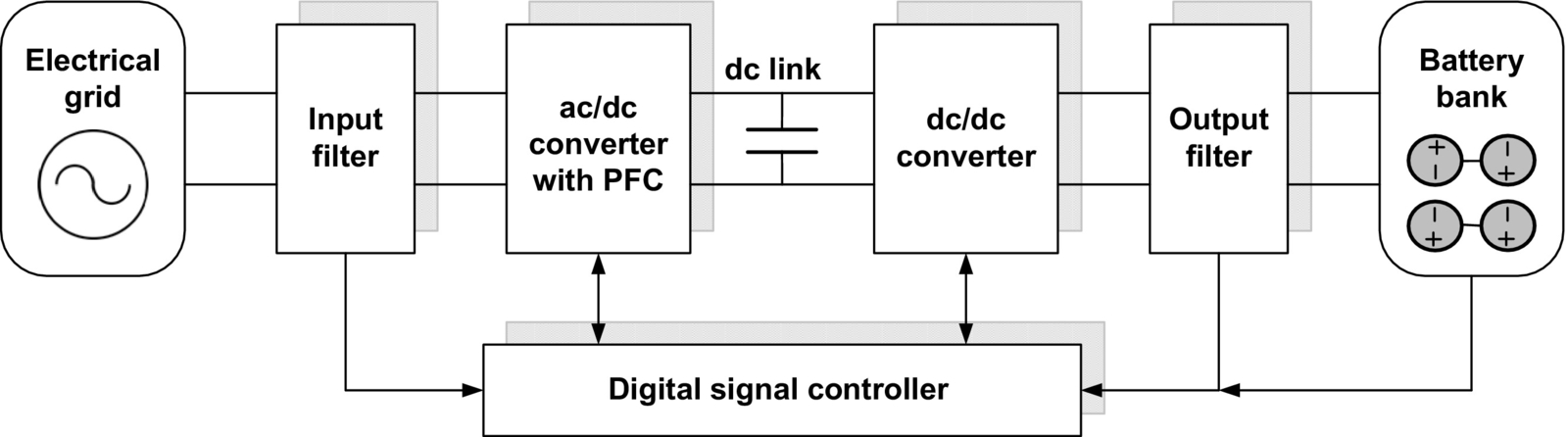
The availability of infrastructure for charging facility will help to reduce the size and capacity of onboard ESS, and consequently, cost and size will be reduced. Charging stations are classified as three types, on the basis of power-handling capacity, charging time, and location of charger installation. Type-I charging is the slowest method of charging, designed for home or business sites with readily available power outlet, and no additional infrastructure is required. It uses standard 120/230 V, 15 A single-phase charger outlet with standard J1772 connector [85]. In type-II charging, dedicated infrastructure and charging equipments are required, which be installed either on board or off-board to avoid redundancy in PEC. It charges battery with 240 V, 80 A single-phase or three-phase and offers fast charging compared with type-I charging. The BEVs/PHEVs owners are likely to prefer type-II charging technology due to its faster charging time and standardized vehicle-to-charger connection. Type-III charging is a commercialized fast charging method and offers the possibility of charging in less than 1.0 h. It can be installed in highway and city refueling points, analogous to conventional fuel stations. It typically operates with 480 V and requires an off-board charger to provide regulated power conversion. The SAE J1772 standard prescribes that type-I and type-II charging infrastructures should be installed on board, whereas type-III chargers should be mounted off-board. It is expected to use type-I and type-II charging stations to enable fast charging in public and private places with less impact on utility [86]. However, type-III charging can increase peak demand and has the potential to quickly overload local distribution system and equipment at peak times. The charging characteristics and infrastructure aspects for different type of charging methods are presented in [72] and are given in Table 31.11.
Table 31.11
Charging types and power level [72]
| Charging type | Charger location | Charger interface | Power rating (kW) | Charging time (h) | Vehicle technology |
| Type-I | Onboard One-phase |
Home outlet | 1.4 (12 A) 1.9 (20 A) |
4–11 11–36 |
BEV (5–15 kWh) PHEV (16–50 kWh) |
| Type-II | Onboard One-phase |
Dedicated public or private outlet | 8 (32 A) 19.2 (80 A) |
1–4 2–6 |
BEV (5–15 kWh) PHEV (16–30 kWh) |
| Type-III | Off-board Three-phase |
Dedicated commercial outlet | 50 100 |
0.4–1 0.2–0.5 |
BEV (20–50 kWh) |

Battery chargers for BEVs/PHEVs can be classified as follows:
I. On-board and off-board charger
II. Unidirectional and bidirectional charger
III. Integrated charger
IV. Inductive charger
On-board and off-board charger
The onboard charger should be installed in the vehicle and designed for the slow charging rate, that is, it takes longer time to charge relatively. Due to limitation in available space in vehicle and payload, the onboard charger for BEVs/PHEVs should be light and compact in design. The advantage of onboard charger is that the battery can be charged at anyplace where there is electric outlet is available. An off-board battery charger is less constrained by size and weight and keeps redundancy in power electronic converters, which adds flexibility in the system. The onboard and off-board charger are usually implemented either with unidirectional or bidirectional power flow. Initially, the unidirectional charging should be the first step because it reduces power electronic component requirement, simplifies interconnection issues and control complexity, and reduces battery degradation [85]. These chargers typically use a diode bridge rectifier in conjunction with a power factor correction (PFC) and dc-dc converters [85].
Unidirectional and bidirectional charger
The classification of conventional unidirectional and bidirectional charger topology is shown in Fig. 31.37. The classification is made on the basis of operation of particular PEC topologies. A unidirectional PEC topology for a type-I battery charging system [87] is shown in Fig. 31.38. Simple control and operation of unidirectional chargers make it relatively unproblematic for a utility grid to manage heavily loaded distribution network to charge multiple BEVs at a time [88]. Battery charger with active front-end converter can control the supply current phase angle to deliver reactive power without discharging the battery. In unidirectional charging, it needs to optimize charging strategy to maximize the benefits and to minimize the impact on distribution system [87,88]. For high penetration of BEVs/PHEVs and active control of charging current, unidirectional chargers can meet practically all the objectives of the utility grid.


The conventional boost converter topology with PFC as battery charger is shown in Fig. 31.39 that is very popular configuration for unidirectional battery charging. A dedicated diode bridge rectifier is used to rectify the ac input voltage to dc that is further converted to dc followed by boost section. In this topology, the output ripple current, which is a difference between diode current and dc output current, is very high [89]. To reduce the current ripple, the interleaved boost converter is presented as shown in Fig. 31.40. It consists of two boost converters in parallel operating 180 degrees out of phase [88,90]. The input current is the sum of the two input inductor currents that are out of phase and consequently cancel out each other, reducing the current ripple and stress across dc-link capacitor. The advantages of interleaved boost converter are parallel-connected switches that increase flexibility, switching out of 180 phase which increases the effective switch frequency and causes the reduction in filter size with lesser ripple content.


A bidirectional charging system supports grid-to-vehicle (G2V) and vehicle-to-grid (V2G) operation by injecting power to the grid and power stabilization with adequate power conversion [73,91,92]. A conventional bidirectional charger process supplies power in two stages. In the first stage, an active grid connected bidirectional ac/dc converter integrated with EMI filter and PFC is connected that enforces power factor to be close to unity. In the second stage a dc/dc converter is connected to regulate charging voltage and current [72]. In charging mode, charger should draw sinusoidal current with defined phase angle to control active and reactive power. In discharging mode, the charger should feed back power to the grid with sinusoidal current [91]. In ac/dc and dc/dc conversion, isolated and nonisolated converter topologies are used. An isolated bidirectional dual active bridge battery charger system is shown in Fig. 31.41 that offers high power density and fast control; however, the large number of component's count can add to cost [25].

The development of charger infrastructure with bidirectional power flow is growing rapidly; however, it imposes some serious challenges and issues such as reduction in battery life due to frequent charging and discharging, increased cost of charger, upgradation of existing distributed network, metering, and pricing [92]. Successful implementation of battery charger with bidirectional power flow needs to solve the abovementioned issues. Also, it requires extensive safety measures and anti-islanding protection [92]. A unidirectional charger can be used for types I, II, and III charging; however, bidirectional chargers that are expected only for type-II charging system due to output power limit and cost target that are low and relatively high degree of freedom and flexibility in operation.
Integrated charger
At present, the onboard chargers face constraints on weight, volume cost, and space over specific power capacity of the battery. To overcome the abovementioned problems, charger configuration with integrated propulsion inverter-motor drive has been proposed [93,94]. The concept of integrated charger is feasible only if the vehicle is at rest. In an integrated charger, the propulsion inverter serves as a bidirectional ac/dc converter, and motor windings are used as filter inductors. Low cost, high-power-density bidirectional power flow, and fast charging with unity power factor are the advantages of the system. However, extra component requirement and control complexity are some of the challenges in its successful implementation. The schematic of a typical single-motor- and single-converter-based integrated charger system is shown in Fig. 31.42.

The classification of integrated charger topologies is done on the basis of the number of total converter and motor used such as one motor with a converter topology, one-motor and two-converter topology, and two-motor and two-converter topology [93–97]. A two-motor and two-converter integrated charger system is shown in Fig. 31.43 as discussed in [95]. In this system, main converter is used to drive the main motor, and auxiliary converter is used to drive the auxiliary motor during propulsion. During charging, two converters operated as ac/dc converter, and three-phase windings of the two motors act as filter inductor with neutral point connected to the grid [95,96]. The main converter recovers energy from main motor during regenerative braking for battery charging while maintaining the driving force for propulsion. The auxiliary converter coupled with auxiliary motor serves the purpose of starting of ICE and battery charging. This configuration of integrated charger is more popular for PHEVs. The inherent disadvantages of this integrated charger are the large number of extra components (twelve power switches, three contactors, and two motors) and control complexity.

A dual-inverter, single-motor integrated charger topology is shown in Fig. 31.44, where one motor with a double set of stator windings comprises two motor halves [97]. The working principle of this configuration is similar to two-motor and two-inverter configuration. However, in this configuration, elimination of one motor leads to reduction in cost and weight but still requires three contactors, 12 power switches, and a specially designed dual winding motor.
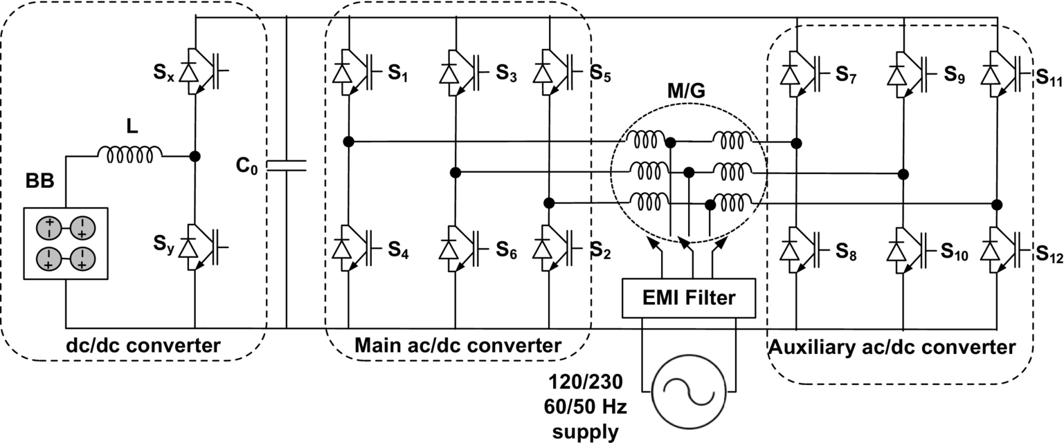
Inductive charging
In conductive charging systems, battery bank is directly connected to the power outlet through charger connecting cable [98]. The standard charging port like domestic power outlets (type I and type II) or commercialized charging station (type II and type III) can be used for battery charging. However, in conductive charging, vehicles need to be parked and plugged into charging outlet.
As an alternative, inductive power charging concept has been introduced and mostly known as inductive power transfer (IPT). In IPT, the energy from power outlet is transferred to the onboard battery magnetically. The basic scheme of the IPT is illustrated in Fig. 31.45. The working principle of IPT is based on the magnetic coupling between two coils of a very-high-frequency transformer. The first coil of the transformer is mounted on the charger side, and the second coil is installed on the vehicle. Single-phase or three-phase ac supply of frequency 50–60 Hz is first rectified to dc, and then, this rectified dc is inverted to very-high-frequency ac within the charging station. This high-frequency power is transferred to the onboard battery through magnetically coupled primary and secondary coil. This high-frequency ac power received through vehicle side coil is converted to dc to charge the battery on board. The clear advantages of IPT are elimination of charger connectors, user convenience, and galvanic isolation. Also, it is possible to build charging strips on road, which enables charging while driving as shown in Fig. 31.46. Relatively low power density and reduced efficiency, high control complexity, and manufacturing cost are some of the major disadvantages of this method [99–101].

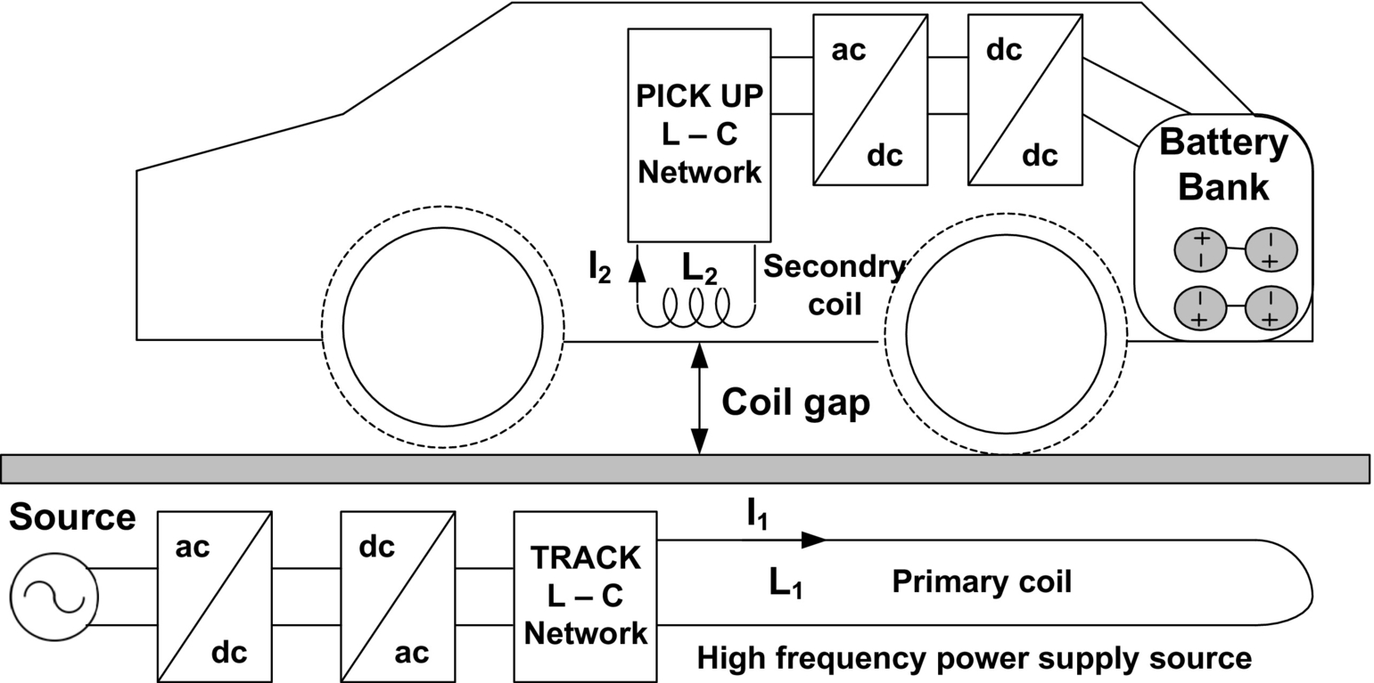
31.5 Electronic Control Unit
The electronic control units (ECU) are designed to provide supervisory control of electric vehicular system [102]. It is a combination of dedicated system control software and electronic circuitry that includes interfacing hardware, sensing circuitry, driver and isolator circuitry, and communication buses. Basically, ECU is the integration of sophisticated electronic circuitry; dedicated digital controllers like microprocessors, microcontrollers, digital signal processors (DSP), and/or field programming gate array (FPGA); and modeling and simulation tools with autocode generation systems like MATLAB/Simulink, ADVISOR, PSAT, PSIM, SABER, SIMPLORER, and VTB, along with embedded software [26,102,103].
ECU provides the flexible multi-input/multi-output channels for communication among various components of the vehicular system. The controller synchronizes or coordinates with the components of EPS such as ESSS, PEC, electric motors along with ICE, transmission system, pilot commands, and operating modes of the vehicle. The ECU controls and maps the status of electric motor, ICE, and vehicle behavior based on a selection of system inputs. Standard pilot commands, such as braking and acceleration, are supplied as system input to the ECU from appropriate sensors and CAN buses. Based on system input and CAN bus information, certain mappings of different system components are performed to monitor their current status to select the vehicle's mode of operation [104,105]. The entire information is processed in digital controllers through programming, which performs the required calculation and converted into desired power and/or torque and/or speed commands for each wheel individually or simultaneously. The output of ECU that is driving signals for various components of the vehicle is communicated through CAN transmitter over different sections of vehicles. Not only the ECU is able to implement a variety of advanced vehicle control and dynamic algorithms, but also it monitors overall vehicle behaviors and observes the performance. The ECU is placed near to motor drives and engine; therefore, it should be designed such that it can bear temperature ranging from 80°C to 140°C and extreme vibrations that are a major challenge. A self-explanatory architecture of the ECU is shown in Fig. 31.47.
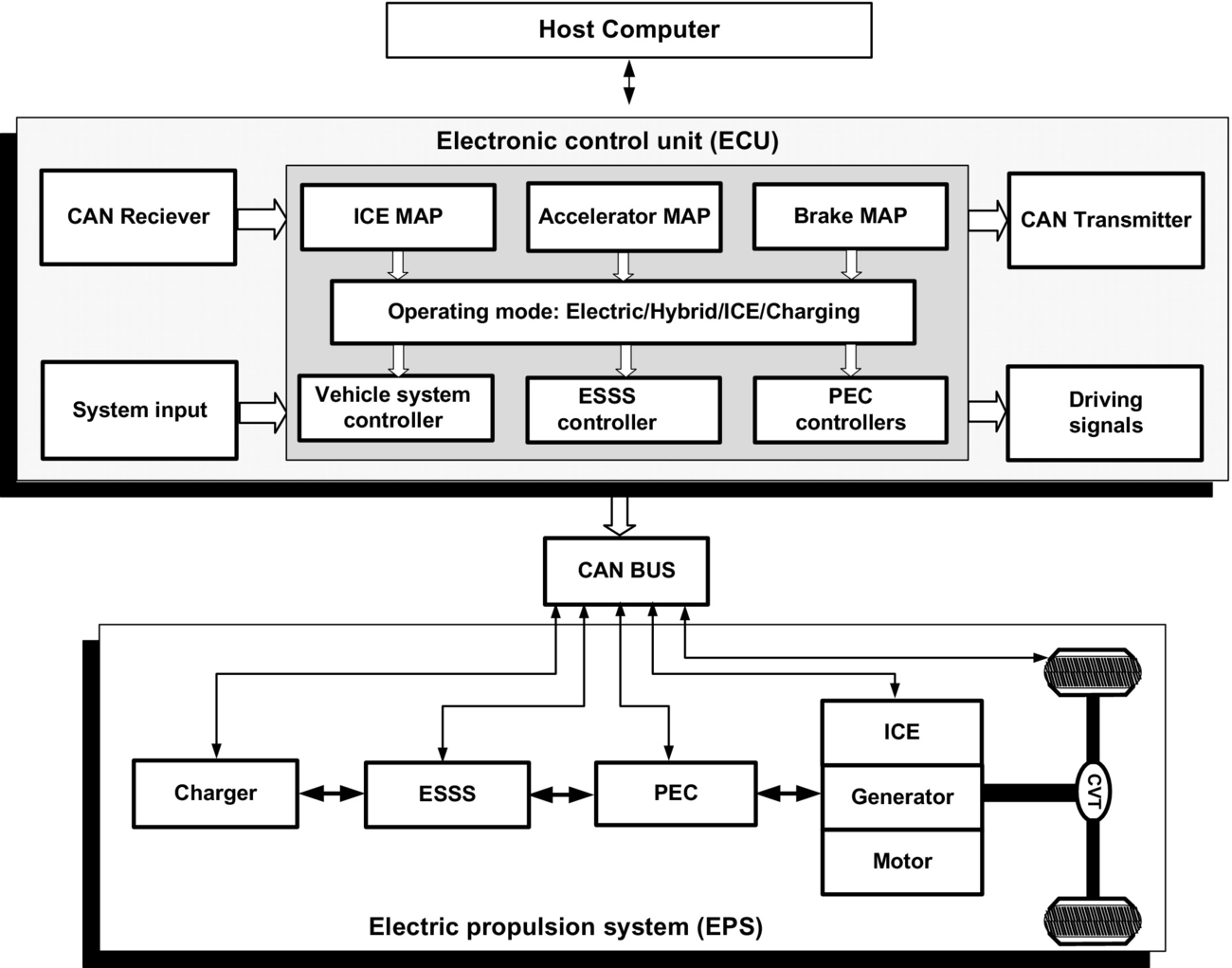
31.6 Power Management and Control Algorithm
In EVT, the control and management of power flow from multiple energy sources to power electronic converters and from converters to different vehicle loads is a major challenge. The technological advancement transforms the early ON/OFF control system to modern adaptive predictive control era that improves the overall performance of control system [106,107]. Dedicated efforts are being given for the development of appropriate control and energy management strategy that is very essential, specifically in HEV operation.
A control strategy is defined as an algorithm, which is a set of instructions or laws regulating the overall operation and power flow of the vehicular system. The algorithm can be considered as a black box that performs desired calculation on the basis of given information. Input information mainly contains measured data of vehicle's operating condition such as acceleration, braking, torque demand, traffic information, and driving profile. The output of the algorithms is a decision that commands the driver circuits to turn ON or OFF the vehicle's components or to modify their operating region toward optimization [106]. A properly developed control algorithm and management strategy should satisfy certain objectives such as vehicle power demand, monitoring of battery's state of charge, fuel economy, reduced emission, efficiency optimization, and smooth coordination between electric and mechanical components. Therefore, it becomes prime concern to adopt systematic process for power-flow control and optimization while designing the controllers and control algorithms.
Controllers are mainly classified into two groups based on their mathematical modeling strategy: (1) rule-based systems and (2) optimization-based systems [107]. The detailed classification of both the controllers is given in Fig. 31.48. Basically, rule-based controllers are designed to obtain maximum fuel economy and efficiency and reduced emission for predefined driving profiles. Rule-based controllers are tuned based on sets of rules or criteria written on the basis of vehicle information. In this controller, state diagram and flow charts are commonly used for performance optimization of each component individually rather than cumulative. On the other hand, optimization-based controllers are designed to develop optimal control strategy for propulsion system by reducing the cost function. The cost function is derived based on the past and future information of driving profile, component parameters, and expected performance of the vehicles.

This controller is tuned for overall vehicular system optimization rather than component level. Both the controllers have their own pros and cons that are summarized in Table 31.12 and need to be addressed properly before implementing the algorithms. The global control strategy with real-time optimization has been the best proposed solution for HEV/PHEV so far [106].
31.7 Summary
Contemporary and futuristic global scenario of environmental, economical, and technological factors has accelerated the interest toward partial and/or complete electrification of vehicular technology. In this chapter, topological configuration of different vehicles has been presented with emphasis on EPS and its components to understand the fundamentals of EVT. The comprehensive review of the electrified vehicle architecture and EPS shows that EVT is a promising technology for sustainable future transportation system. At present, HEVs are dominating vehicle configurations, emerging rapidly and capturing the significant market space at very fast growth rate. Suitable energy policy and infrastructures for charging station will accelerate the commercialization of plug-in HEV very soon in the near future, and it will sustain for long time. FCVs are under development stage, and it will take time for their successful commercialization. FCV can be seen as the future of transportation system in long run.
The comprehensive review of EPS indicates that the recent modification in EPS due to technological advancement of its members, like ESS, PEC, EM, and ECU, makes EVT capable enough to compete against conventional ICE-based vehicular technology. Among all the components, PECs play crucial role as it bears the responsibility of compatible integration proper coordination among all the electric, mechanical, and electronic components on board. Also, the PEC controls and manages power flow from different energy sources and vehicle loads at appropriate voltage level and hence behaves as a heart of EPS in vehicle architecture. The integration and packaging of different components of EPS along with power electronic components are the challenging issues that need to be addressed properly so that weight, volume, and cost can be reduced significantly. For successive advancement of EPS, technical breakthroughs are necessary from device level to system level, so that improved performance, higher efficiency, longer driving distance, and higher degree of reliability can be achieved from electrified vehicles.