This part is just about creating a camera and a level to use in our platform game. We will be creating a camera that will show all the objects in the scene and follow our character movement.
Before we start creating this project, we will create the project in Unity by following these steps:
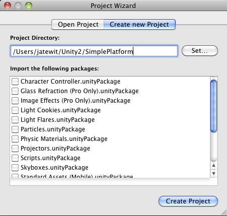
- Create a new project by going to File | New Project to bring up the Project Wizard window. Next, click on the Create new Project tab and set the Project Directory as you want, as we can see in the following screenshot:
- Import the
Chapter1package folder that you downloaded into the project assets folder, by copying it into the project's Assets folder or drag-and-dropping it into the Unity window, as we can see in the following screenshot: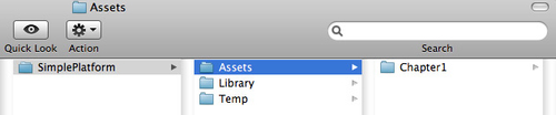
- Go back to Unity and make sure that you have
Planeandbackground.pngin yourProjectfolder, as shown in the following screenshot: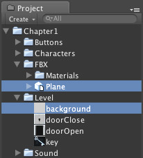
- Click on the
Planeobject in the Project view to bring up its Inspector view. Next, we go to the FBXImporter | Meshes component, and set the Scale Factor to 1, as shown in the following screenshot, and click on the Apply button: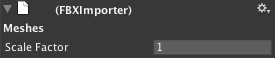
We are now ready to start, so let's get on with it!
- Let's start by creating the background with the
Planeprefab object in theFBXfolder—go to the Project view, click on the Plane prefab object, and drag it into the Hierarchy view.Note
There is also the Unity built-in
Planeobject that you can use, but you don't really want to use it, because the Unity built-inPlaneobject will have way too many triangles for our 2D objects. As we can see from the following screenshot, our prefabPlaneonly has two triangles, but the Unity built-inPlaneobject will have around 200 triangles.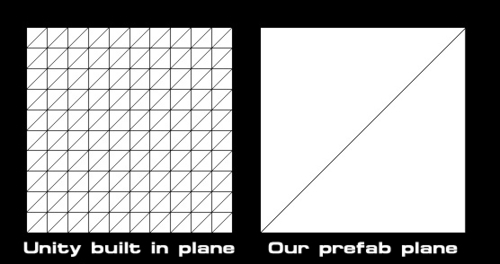
- In the Hierarchy view, right-click on the Plane prefab object, and choose Rename to change the name to Background.
- Then, click on this object and go to its Inspector view, and set its transform Position to X: 0, Y: 0, Z: 24, Rotation to X: 0, Y: 180, Z: 0, Scale to X: 200, Y: 200, Z: 1.
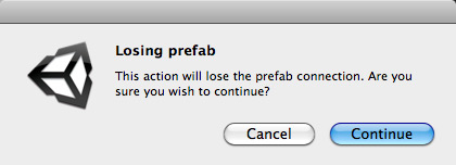
- Right-click on the Animation component in the Inspector view and choose the Remove Component option to remove it, as shown in the following screenshot:

This will bring up the pop-up window, as shown in the following screenshot. Click on the Continue button to break the prefab:
- Now, to create the background material, go to Assets | Create | Material, and name it whatever you want; here we will call it M_Background. Then, we assign our background texture to this material, in the project window click on M_Background. We will see the Inspector view of the background material, as shown in the following screenshot:
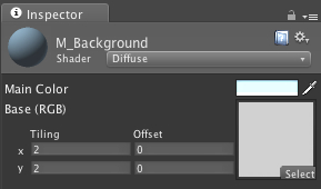
- Next, drag the
background.pngfile from theChapter1/Levelfolder in the Project view and drop it in the texture thumbnail, and then set the following:- Shader: Diffuse
- Main Color:R:164, G:219, B:225, A: 255
- Base (RGB): x-Tiling: 2, Offset: 0; y-Tiling: 2, Offset: 0
Now, we are adding our material to the background object, click on
Backgroundobject in the Hierarchy view to open the Inspector view, and in Mesh Renderer | Materials, set the parameters as follows:- Size: 1
- Element 0: M_Background
- Next, we will create a new
TagandLayerfor ourBackgroundobject; go to Edit | Project Settings | Tags and click on the arrow next to the Tags option to open it, as shown in the following screenshot: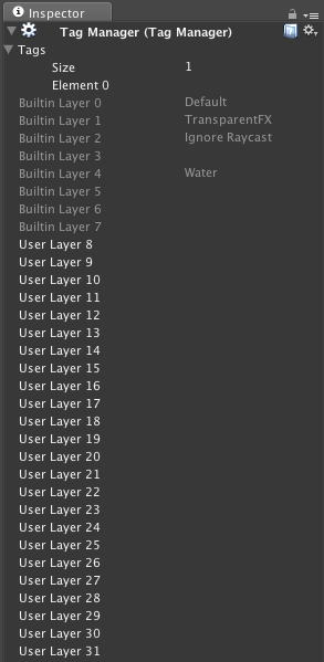
- Enter the parameters as follows:
For Element 0 type Background, for Element 1 type Floor, for Element 2 type Wall, and then for User Layer 8 type Background, for User Layer 9 type Level; we select our
Backgroundobject, and then go back to theBackgroundobject's Inspector view setup as follows:- Tag: Background
- Layer: Background
- Set the Main Camera, which is already in our scene when we first create the project, as follows:
- Position: x: 0, y: 0, z: -20
- Projection: Perspective
- To light up our scene by adding sound light into it, go to GameObject | Create Other | Directional Light and set its parameters as follows:
- Rotation: x:20, y:0, z:0
- For the last step, we will create our quick, easy, and simple level:
- First, we need to create our container to contain all the objects for the level. Go to GameObject | Create Empty or use Command + Shift + N in Mac and Ctrl + Shift + N in Windows, and change the name to Level, and reset the transform position to X: 0, Y:0, Z: 0), rotation to X: 0, Y: 0, Z: 0, and scale to X: 1, Y: 1, Z: 1.
- For creating our floor, let's go to GameObject | Create Other | Cube, change the name of this object to Floor, and change the tag and layer as follows:
- Tag: Floor
- Layer: Level
- Same thing for creating a wall; just repeat the same step and change the name to Wall, and set the tag and layer as follows:
- Tag: Wall
- Layer: Level
So, now we have our Floor cube and Wall cube.
- Next, we want to apply the material to our cubes. We will have only one material for both the floor and wall to make it simple. Go to Assets | Create | Material, name it M_Level, adjust the color to R: 150, G: 230, B: 225, A: 255, and apply this material to the
FloorandWallobjects by dragging the materialFloorandWallobjects in the Hierarchy view. Then we drag-and-dropFloorandWallinside ourLevelobject, as shown in the following screenshot: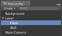
- Now, we will click on the
floorobject in the hierarchy, and press Command + D for Mac users or Ctrl + D for Windows users to copy it six times, and click on thewallobject in the hierarchy and copy it twice. So now we have sevenfloorobjects and threewallobjects. - Next we create our level by setting up the position and scale of our
floorandwallobjects. Let's set them up as follows:- 1st Floor object: Position: x: -4, y: -9, z: 0 Scale: x: 125, y: 15, z: 1
- 2nd Floor object: Position: x: -6, y: 5, z: 0 Scale: x: 32, y: 1, z: 1
- 3rd Floor object: Position: x: -25, y: 12, z: 0 Scale: x: 19.5, y: 1, z: 1
- 4th Floor object: Position: x: 14, y: 12, z: 0 Scale: x: 20, y: 1, z: 1
- 5th Floor object: Position: x: -7, y: 9, z: 0 Scale: x: 9, y: 1, z: 1
- 6th Floor object: Position: x: -31, y: 1, z: 0 Scale: x: 6, y: 1, z: 1
- 7th Floor object: Position: x: 21, y: 2, z: 0 Scale: x: 10, y: 1, z: 1
- 1st Wall object: Position: x: -49, y: 17, z: 0 Scale: x: 36, y: 40, z: 1
- 2nd Wall object: Position: x: 42, y: 17, z: 0 Scale: x: 38, y: 39, z: 1
- 3rd Wall object: Position: x: -7, y: 23, z: 0 Scale: x: 1, y: 36, z: 1
- Finally, we will save the scene by pressing Command + s in Mac or Control + s in Windows. Since it is our first save, we will be asked to name this scene, so let's name it SimplePlatform.
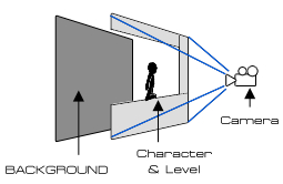
Basically, what we have done here is create a Background object behind the Level object, and set the Main Camera in front of the Level object. Our Main Camera will also follow our character while he is moving. This way we can make sure that the player will always see our character and background image. We can set our scene and level, as shown in the following diagram:
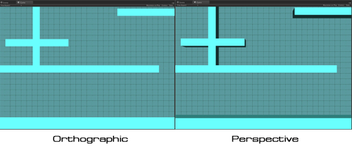
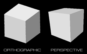
In our Main Camera, we set the Projection to Perspective because we want to show the thickness of our level and the depth of the object, which will give a nice view for the player.
We can set the Camera Projection in our scene to be either Orthographic or Perspective. The difference between both projections is that with the Orthographic Projection, the object won't scale by the distance of the camera. So in our scene, we will see only one side of the object that faces the camera. On the other hand, in Perspective Projection we will see the depth of the object that will scale down by the distance of the camera, which is very similar to real life.
In our scene, we won't see any significant difference on our background object because our background object is a plane and doesn't have any thickness on it, but if we are trying to adjust the Projection of our camera, we will see the difference between the two projections. We can do this by going to the Hierarchy view, clicking on Main Camera, changing Projection to Orthographic, and Size to 8.5, and then changing Projection back to Perspective. The difference is shown in the following screenshot: