
From the last step, we have a FBX model ready to use in Unity. In this step, we will import Chapter3.unitypackage
(which is already included in the FBX model that we export from the 3D Studio Max), and begin creating a shader programming, which will include all properties that we can edit from the Material Inspector. We will start with assigning the diffuse and bump (normal) map. Then, we will use the Lambert lighting model, which comes with Unity, to see our result.
Now, we can start the shader programming by implementing the following steps:
- Let's create a new project named
Shadersimilar to that in the last chapter and click on the Create Project button, as shown in the following screenshot: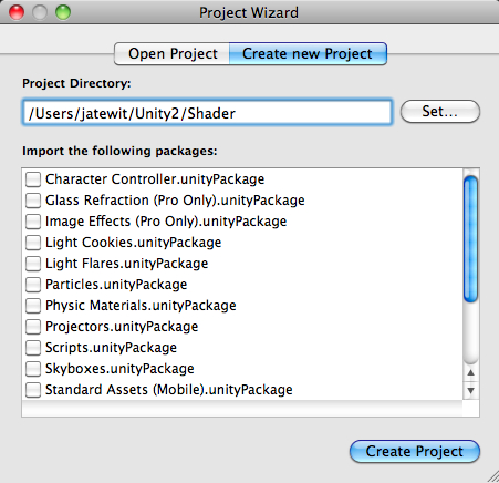
- Import the assets package by going to (Assets | Import Package | Custom Package...), choose the
Chapter3.unityPackage, which we downloaded earlier, and then click on the Import button in the pop-up window, as shown in the following screenshot: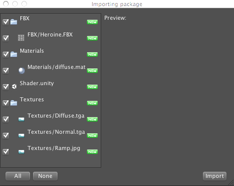
- Wait until it's done, and you will see the FBX, Materials, and Textures folders, as we can see in the following screenshot:
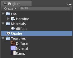
- Next, double-click on the Shader scene, as shown in the preceding screenshot, to open the scene that we will work on in this chapter. When you double-click on the Shader scene, Unity will bring up the pop-up and ask whether we want to save the current scene or not, similar to what we saw in the last chapter. Just click on the Don't save button to open up the Shader scene.
- Then, go to the
FBXfolder, and click onHeroine.FBXin this folder to bring up its Inspector view. In the Inspector view, make sure that the (FBXImporter) | Scale Factor properties equals 1, and then click on the Apply button, as shown in the following screenshot: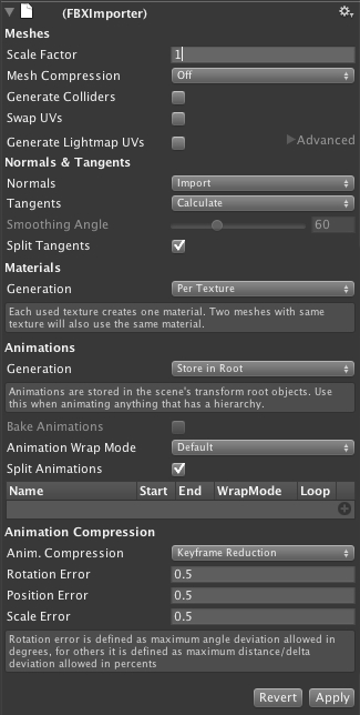
- Then, go to the
Texturesfolder, and click onNormal.tgato bring up its Inspector view. In the Inspector view, change the (Texture Importer) | Texture Type to Normal Map, then uncheck Generate from greyscale, and click on the Apply button, as shown in the following screenshot: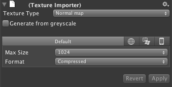
Here, we will put the 3D model into our scene and start writing our custom shader programming:
- First, we drag the
Heroine.FBXmodel in theFBXfolder from the Project view to the Hierarchy view. - Next, we will click on the
Heroine.FBXmodel in the Hierarchy view to bring up its Inspector view. Then, we will go to the Inspector view and set rotation Y to 180, as shown in the following screenshot: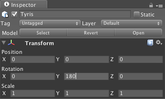
Note
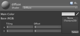
If we go to the material component, we will see Diffuse applied to the Shader in this material, which has two properties: Main Color and Base (RGB). Main Color takes the color that we can edit and it will apply the color to our model. Base (RGB) takes the texture, which is used for our model. Both properties can be edited and adjusted in the Unity editor to get the best look for our model, as shown in the following screenshot:
- Now, we will start coding by going to Assets | Create | Shader, and naming it
MyShader. Then, we right-click on it and choose Sync MonoDevelop Project to open our MonoDevelop. - In MonoDevelop, you will see the default setup of the shader script, as shown in the following screenshot:
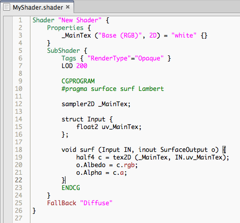
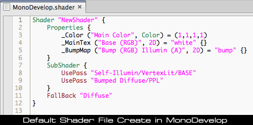
- Next, go to the first line in
MyShader.shaderand modify the existing code as follows:Shader "My Shader/Toon Rim Light" {In this line, we change the position and name our shader, which will appear in the drop down Shader when we select the Shader properties in the object's Inspector view.
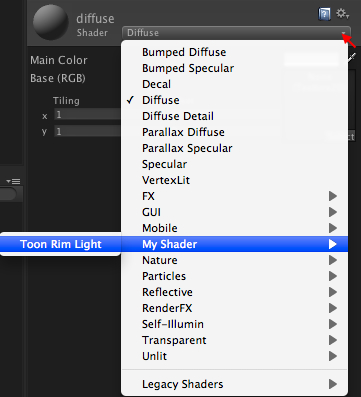
- Then, go back to Unity and click on the
Heroine.FBXmodel in the Hierarchy view to bring up its Inspector. - In the Shader properties in the material component, we will click on the small arrow on the right side to bring up the drop-down, then select the My Shader | Toon Rim Right, as shown in the following screenshot:
- Then, we go back to MonoDevelop again, and go to the next line of the
MyShader.shaderand start modifying thePropertiessection, as follows:Properties { _MainTex ("Texture", 2D) = "white" {} _BumpMap ("Bumpmap", 2D) = "bump" {} }Then, we go to
SubShadersection to modify and add the following code:SubShader { Tags { "RenderType"="Opaque" } LOD 300 CGPROGRAM #pragma surface surf Lambert sampler2D _MainTex; sampler2D _BumpMap; struct Input { float2 uv_MainTex; float2 uv_BumpMap; }; void surf (Input IN, inout SurfaceOutput o) { half4 c = tex2D (_MainTex, IN.uv_MainTex); o.Albedo = c.rgb; o.Alpha = c.a; o.Normal = UnpackNormal (tex2D (_BumpMap, IN.uv_BumpMap)); } ENDCG } - Finally, we go back to Unity and apply the texture to our model.
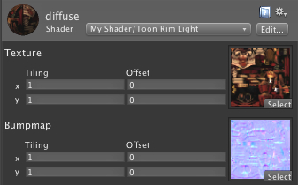
Let's click on the Heroine.FBX model in the Hierarchy view to bring up its Inspector view. In the Inspector view, we will go to the material component and set the following:
- Texture: Drag-and-drop the
Diffuse.tgain theTexturesfolder from the Project view to this thumbnail - Bumpmap: Drag-and-drop the
Normal.tgain theTexturesfolder from the Project view to this thumbnail
You will see the Inspector view, as shown in the following screenshot:
Now, click Play and behold the result:

Let's take a look at what we did here.
First, we added the new property (_BumpMap), which will be used to get the surface normals from our character.
Properties can be created by using the following syntax:
name ("display name", property type) = default value
nameis the name of property inside the shader scriptdisplay nameis the name that will be shown in the material inspectorproperty typeis the type of the property that we can use in our shader programming, which can beRange,Color,2D,Rect,Cube,Float, orVectordefault valueis the default value of our property
Note
Every time you add new properties in the Properties section, you will need to create the same parameter inside the CGPROGRAM in the SubShader section, as shown in the following code:
Properties {  _BumpMap ("Bumpmap", 2D) = "bump" {}  }
SubShader {
    .........
    CGPROGRAM
    #pragma surface surf Lambert
    sampler2D _BumpMap;
    ........
    ENDCG
}
We can see more details at the following website and see what each parameter does:
http://unity3d.com/support/documentation/Components/SL-Properties.html
Then, we set LOD (Level of Detail) for our shader to 300. The Level of Detail is the setup that will limit our shader to use the maximum of detail to the number that we set. We used 300 because we have included the bump map to our shader, which is the same number of the Unity built-in setup for the diffuse bump. You can take a look at the following link to get more information on the Shader Level of Detail:
http://unity3d.com/support/documentation/Components/SL-ShaderLOD.html
We added the sampler2D _BumpMap; line, which is the same property that gets passed from the Properties section ( _BumpMap ("Bumpmap", 2D) = "bump" {}).
Note
sampler2 is basically the type of parameter that is used in the Cg/HLSL shader programming language, which is a two-dimensional texture. We can get more information about the Cg parameter from the following website:
http://http.developer.nvidia.com/CgTutorial/cg_tutorial_chapter03.html
Next, we added float2 uv_BumpMap in struct Input {}, which will be used to calculate the color information from our _BumpMap. The uv_BumpMap parameter is the texture coordinate, which is the vector2.
In the surf() function, we have the following:
half4 c = tex2D (_MainTex, IN.uv_MainTex);
  o.Albedo = c.rgb;
  o.Alpha = c.a;
  o.Normal = UnpackNormal (tex2D (_BumpMap, IN.uv_BumpMap));
Note
surf(Input IN, inout SurfaceOutput o) function is basically the function that will get the input information from struct Input {}. Then, we will assign the new parameter to SurfaceOutput
o. This parameter will get passed and used next in the vertex and pixel processor.
We can get more details on the Input
struct and the default parameter of SurfaceOutput
struct here:
http://unity3d.com/support/documentation/Components/SL-SurfaceShaders.html.
The tex2D function will return the color value (Red, Green, Blue, Alpha) or (R,G,B,A) from the sample state (_MainTex) and the texture coordinate (IN.uv_MainTex), which we will then assign to the o.Albedo and o.Alpha. The o.Albedo parameter will store the color information (RGB) and the o.Alpha parameter will store the alpha information.
Note
"Albedo or reflection coefficient, is the diffuse reflectivity or reflecting power of a surface. It is defined as the ratio of reflected radiation from the surface to incident radiation upon it."
Reference from http://en.wikipedia.org/wiki/Albedo
The next line is to get the normal information, which is the vector that contains the position (x, y, and z). Then, we used the tex2D function to get the color value (R,G,B,A) from the sample state (_BumpMap) and the texture coordinate (IN.uv_BumpMap). Then, we used the UnpackNormal function to get the Normal as the result of the tex2D function.
Talking about shader programming, there are a lot of things to get to know and understand, for example, how the shader works. We will take a look at the basic structure of the shader programming in Unity.
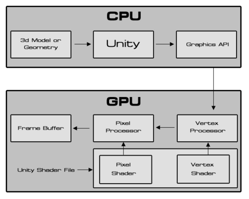
Note
The preceding diagram is from Amir Ebrahimi and Aras Pranckevčius, who presented the Shader Programming course at Unite 2008, and represents how the shader works in Unity. We can get more information from the following website. (Warning: this presentation might be difficult to understand, since it showed how to create the shader without using any surface shader and it used the old version of Unity.)
http://unity3d.com/support/resources/unite-presentations/shader-programming-course
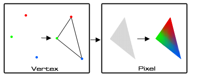
Let's get back to the diagram—you will see that the shader file that we are writing is working on the vertex and pixel (fragment) level. Then, it will show the result to the frame buffer, but what are vertex and pixel shaders? These are the different types of processors in the GPU. First, the vertex processor gets the vertex data, which is the position and color of each vertex in the 3D model; then, draw a triangle from these vertices and pass the data to the pixel processor. The pixel processor will get that value and translate it to the per pixel screen. It is similar to taking a vector art from Illustrator or Flash and translating it to a pixel art in Photoshop. Then, it interpolates color data to each pixel, as shown in the following diagram:
From the explanation, we know that we need to deal with the vertex and pixel shader programming when we want to write a shader program. For example, if we want to create a shader, we will need to get the vertex data from our geometry, calculate the data, and pass it out to the pixel level. At the pixel level, we will calculate the color of the geometry, light, and shadow, and then we will get the result.
However, this can be very complex when we have to handle lighting manually. That's why we are using the surface shaders, so we don't have to deal with various types of lightning, rendering, and so on.
If you check out the ShaderLab link in Unity, you will see that there are a lot of things to do, but don't be afraid because we don't need to understand everything that's there to create our custom shader. In the next step, we will create the custom lighting models in surface shaders.