
Power Electronics for Renewable Energy Sources
Syed M. Islam Curtin University, Perth, WA, Australia
Chem V. Nayar Curtin University, Perth, WA, Australia
Ahmed Abu-Siada Curtin University, Perth, WA, Australia
Md Mubashwar Hasan Curtin University, Perth, WA, Australia
Abstract
The Kyoto agreement on global reduction of greenhouse gas emissions has prompted renewed interest in renewable energy systems worldwide. Many renewable energy technologies today are well developed, reliable, and cost competitive with the conventional fuel generators. The cost of renewable energy technologies is on a falling trend and is expected to fall further as demand and production increases. There are many renewable energy sources (RES) such as biomass, solar, wind, minihydro, and tidal power. However, solar and wind energy systems make use of advanced power electronics technologies, and therefore, the focus in this chapter will be on solar photovoltaic and wind power.
Keywords
Photovoltaics; Power electronics; Renewable energy; PV systems; Inverter types; Solar water pumping
25.1 Introduction
The Kyoto agreement on global reduction of greenhouse gas emissions has prompted renewed interest in renewable energy systems worldwide. Many renewable energy technologies today are well developed, reliable, and cost competitive with the conventional fuel generators. The cost of renewable energy technologies is on a falling trend and is expected to fall further as demand and production increases. There are many renewable energy sources (RES) such as biomass, solar, wind, minihydro, and tidal power. However, solar and wind energy systems make use of advanced power electronics technologies, and therefore, the focus in this chapter will be on solar photovoltaic and wind power.
One of the advantages offered by (RES) is their potential to provide sustainable electricity in areas not served by the conventional power grid. The growing market for renewable energy technologies has resulted in a rapid growth in the need of power electronics. Most of the renewable energy technologies produce DC power, and hence, power electronics and control equipment are required to convert the DC into AC power.
Inverters are used to convert DC to AC. There are two types of inverters: (a) stand-alone and (b) grid-connected. Both types have several similarities but are different in terms of control functions. A stand-alone inverter is used in off-grid applications with battery storage. With backup diesel generators (such as photovoltaic (PV)/diesel/hybrid power systems), the inverters may have additional control functions such as operating in parallel with diesel generators and bidirectional operation (battery charging and inverting). Grid-interactive inverters must follow the voltage and frequency characteristics of the utility generated power presented on the distribution line. For both types of inverters, the conversion efficiency is a very important consideration. Details of stand-alone and grid-connected inverters for PV and wind applications are discussed in this chapter.
Section 25.2 covers stand-alone PV system applications such as battery charging and water pumping for remote areas. This section also discusses power electronic converters suitable for PV-diesel hybrid systems and grid-connected PV for rooftop and large-scale applications. Of all the renewable energy options, the wind turbine technology is maturing very fast. A marked rise in installed wind power capacity has been noticed worldwide in the last decade. Per unit generation cost of wind power is now quite comparable with the conventional generation. Wind turbine generators are used in stand-alone battery charging applications, in combination with fossil-fuel generators as part of hybrid systems and as grid-connected systems. As a result of advancements in blade design, generators, power electronics, and control systems, it has been possible to increase dramatically the availability of large-scale wind power. Many wind generators now incorporate speed control mechanisms like blade pitch control or use converters/inverters to regulate power output from variable-speed wind turbines. In Section 25.3, electric and power-conditioning aspects of wind energy conversion systems were included.
25.2 Power Electronics for Photovoltaic Power Systems
25.2.1 Basics of Photovoltaics
The density of power radiated from the sun (referred as “solar energy constant”) at the outer atmosphere is 1.373 kW/m2. Part of this energy is absorbed and scattered by the earth's atmosphere. The final incident sunlight on earth's surface has a peak density of 1 kW/m2 at noon in the tropics. The technology of photovoltaics (PV) is essentially concerned with the conversion of this energy into usable electric form. Basic element of a PV system is the solar cell. Solar cells can convert the energy of sunlight directly into electricity. Consumer appliances used to provide services such as lighting, water pumping, refrigeration, telecommunication, and television can be run from PV electricity. Solar cells rely on a quantum-mechanical process known as the “photovoltaic effect” to produce electricity. A typical solar cell consists of a p-n junction formed in a semiconductor material similar to a diode. Fig. 25.1 shows a schematic diagram of the cross section through a crystalline solar cell [1]. It consists of a 0.2–0.3 mm thick monocrystalline or polycrystalline silicon wafer having two layers with different electric properties formed by “doping” it with other impurities (e.g., boron and phosphorous). An electric field is established at the junction between the negatively doped (using phosphorous atoms) and the positively doped (using boron atoms) silicon layers. If light is incident on the solar cell, the energy from the light (photons) creates free charge carriers, which are separated by the electric field. An electric voltage is generated at the external contacts, so that current can flow when a load is connected. The photocurrent (Iph), which is internally generated in the solar cell, is proportional to the radiation intensity.

A simplified equivalent circuit of a solar cell consists of a current source in parallel with a diode as shown in Fig. 25.2A. A variable resistor is connected to the solar cell generator as a load. When the terminals are short-circuited, the output voltage and also the voltage across the diode is zero. The entire photocurrent (Iph) generated by the solar radiation then flows to the output. The solar cell current has its maximum (Isc). If the load resistance is increased, which results in an increasing voltage across the p-n junction of the diode, a portion of the current flows through the diode, and the output current decreases by the same amount. When the load resistor is open-circuited, the output current is zero, and the entire photocurrent flows through the diode. The relationship between current and voltage may be determined from the diode characteristic equation:

where q is the electron charge, k is the Boltzmann constant, Iph is photocurrent, I0 is the reverse saturation current, Id is diode current, and T is the solar cell operating temperature (![]() K). The current versus voltage (I-V) of a solar cell is thus equivalent to an “inverted” diode characteristic curve shown in Fig. 25.2B.
K). The current versus voltage (I-V) of a solar cell is thus equivalent to an “inverted” diode characteristic curve shown in Fig. 25.2B.
A number of semiconductor materials are suitable for the manufacturing of solar cells. The most common types using silicon semiconductor material (Si) are as follows:
• Polycrystalline Si cells
• Amorphous Si cells
A solar cell can be operated at any point along its characteristic current-voltage curve, as shown in Fig. 25.3. Two important points on this curve are the open-circuit voltage (Voc) and short-circuit current (Isc). The open-circuit voltage is the maximum voltage at zero current, while short-circuit current is the maximum current at zero voltage. For a silicon solar cell under standard test conditions, Voc is typically 0.6–0.7 V, and Isc is typically 20–40 mA for every square centimeter of the cell area. To a good approximation, Isc is proportional to the illumination level, whereas Voc is proportional to the logarithm of the illumination level.

A plot of power (P) against voltage (V) for this device (Fig. 25.3) shows that there is a unique point on the I-V curve at which the solar cell will generate maximum power. This is known as the maximum power point (Vmp and Imp). To maximize the power output, steps are usually taken during fabrication; the three basic cell parameters are open-circuit voltage, short-circuit current, and fill factor (FF)—a term describing how “square” the I-V curve is given by
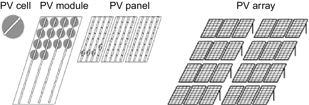
For a silicon solar cell, FF is typically 0.6–0.8. Because silicon solar cells typically produce only about 0.5 V, a number of cells are connected in series in a PV module. A panel is a collection of modules physically and electrically grouped together on a support structure. An array is a collection of panels (see Fig. 25.4).
The effect of temperature on the performance of silicon solar module is illustrated in Fig. 25.5. Note that Isc slightly increases linearly with temperature, but Voc and the maximum power, Pm, decrease with temperature [1].

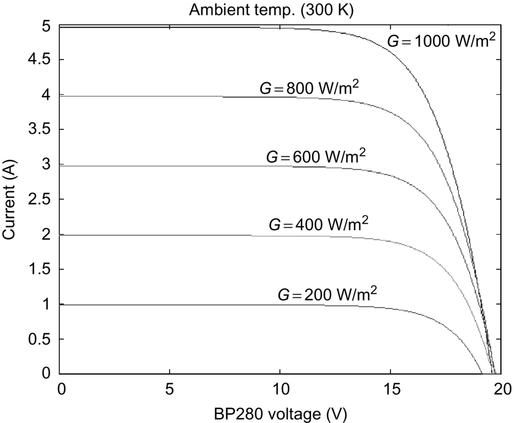
Fig. 25.6 shows the variation of PV current and voltages at different insolation levels. From Figs. 25.5 and 25.6, it can be seen that the I-V characteristics of solar cells at a given insolation and temperature consist of a constant voltage segment and a constant current segment [2]. The current is limited, as the cell is short-circuited. The maximum power condition occurs at the knee of the characteristic curve where the two segments meet.
25.2.2 Types of PV Power Systems
Photovoltaic power systems can be classified as follows:
• Hybrid PV systems
• Grid-connected PV systems
Stand-alone PV systems, shown in Fig. 25.7, are used in remote areas with no access to a utility grid. Conventional power systems used in remote areas often based on manually controlled diesel generators operating continuously or for a few hours. Extended operation of diesel generators at low load levels significantly increases maintenance costs and reduces their useful life. Renewable energy sources such as PV can be added to remote-area power systems using diesel and other fossil-fuel-powered generators to provide 24 h power economically and efficiently. Such systems are called “hybrid energy systems.” Fig. 25.8 shows a schematic of a PV-diesel hybrid system. In grid-connected PV systems shown in Fig. 25.9, PV panels are connected to a grid through inverters without battery storage. These systems can be classified as small systems like the residential rooftop systems or large grid-connected systems. The grid-interactive inverters must be synchronized with the grid in terms of voltage and frequency.


25.2.3 Stand-Alone PV Systems
The two main stand-alone PV applications are as follows:
• Solar water pumping
25.2.3.1 Battery Charging
Batteries for PV systems
Stand-alone PV energy system requires storage to meet the energy demand during periods of low solar irradiation and nighttime. Several types of batteries are available such as the lead-acid, nickel-cadmium, lithium, zinc bromide, zinc chloride, sodium sulfur, nickel-hydrogen, redox, and vanadium batteries. The provision of cost-effective electric energy storage remains one of the major challenges for the development of improved PV power systems. Typically, lead-acid batteries are used to guarantee several hours to a few days of energy storage. Their reasonable cost and general availability has resulted in the widespread application of lead-acid batteries for remote-area power supplies despite their limited lifetime compared with other system components. Lead-acid batteries can be deep or shallow cycling gelled batteries, batteries with captive or liquid electrolyte, sealed and nonsealed batteries, etc. [3]. Sealed batteries are valve regulated to permit the evolution of excess hydrogen gas (although catalytic converters are used to convert as much evolved hydrogen and oxygen back to water as possible). Sealed batteries need less maintenance. The following factors are considered in the selection of batteries for PV applications [1]:
• Deep discharge (70%–80% depth of discharge)
• Low charging/discharging current
• Long duration charge (slow) and discharge (long duty cycle)
• Irregular and varying charge/discharge
• Low self-discharge
• Long lifetime
• Less maintenance requirement
• High-energy storage efficiency
• Low cost
Battery manufacturers specify the nominal number of complete charge and discharge cycles as a function of the depth of discharge (DOD), as shown in Fig. 25.10. While this information can be used reliably to predict the lifetime of lead-acid batteries in conventional applications, such as uninterruptable power supplies or electric vehicles, it usually results in an overestimation of the useful life of the battery bank in renewable energy systems.

Two of the main factors that have been identified as limiting criteria for the cycle life of batteries in PV power systems are incomplete charging and prolonged operation at a low state of charge (SOC). The objective of improved battery control strategies is to extend the lifetime of lead-acid batteries to achieve a typical number of cycles shown in Fig. 25.10. If this is achieved, an optimum solution for the required storage capacity and the maximum DOD of the battery can be found by referring to manufacturer's information. Increasing the capacity will reduce the typical DOD and therefore prolong the battery lifetime. Conversely, it may be more economic to replace a smaller battery bank more frequently.
PV charge controllers
Blocking diodes in series with PV modules are used to prevent the batteries from being discharged through the PV cells at night when there is no sun available to generate energy. These blocking diodes also protect the battery from short circuits. In a solar power system consisting of more than one string connected in parallel, if a short circuit occurs in one of the strings, the blocking diode prevents the other PV strings to discharge through the short-circuited string.
The battery storage in a PV system should be properly controlled to avoid catastrophic operating conditions like overcharging or frequent deep discharging. Storage batteries account for most PV system failures and contribute significantly to both the initial and the eventual replacement costs. Charge controllers regulate the charge transfer and prevent the battery from being excessively charged and discharged. Three types of charge controllers are commonly used:
• Shunt charge regulators
• DC-DC converters
A series charge regulators
The basic circuit for the series regulators is given in Fig. 25.11. In the series charge controller, the switch S1 disconnects the PV generator when a predefined battery voltage is achieved. When the voltage reduces below the discharge limit, the load is disconnected from the battery to avoid deep discharge beyond the limit. The main problem associated with this type of controller is the losses associated with the switches. This extra power loss has to come from the PV power, and this can be quite significant. Bipolar transistors, metal-oxide-semiconductor field-effect transistors (MOSFETs), or relays are used as the switches.

Shunt charge regulators
In this type, as illustrated in Fig. 25.12, when the battery is fully charged, the PV generator is short-circuited using an electronic switch (S1). Unlike series controllers, this method works more efficiently even when the battery is completely discharged as the short-circuit switch need not be activated until the battery is fully discharged [1].

The blocking diode prevents short-circuiting of the battery. Shunt charge regulators are used for the small PV applications (less than 20 A).
Deep discharge protection is used to protect the battery against the deep discharge. When the battery voltage reaches below the minimum set point for deep discharge limit, switch S2 disconnects the load. Simple series and shunt regulators allow only relatively coarse adjustment of the current flow and seldom meet the exact requirements of PV systems.
DC–DC converter type charge regulators
Switch-mode DC-to-DC converters are used to match the output of a PV generator to a variable load. There are various types of DC-DC converters such as the following:
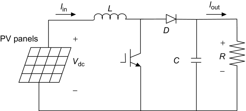
• Boost (step-up) converter
• Buck-boost (step-down/step-up) converter
Figs. 25.13–25.15 show simplified diagrams of these three basic types of converters. The basic concepts are an electronic switch, an inductor to store energy, and a “flywheel” diode, which carries the current during that part of switching cycle when the switch is off. The DC-DC converters allow the charge current to be reduced continuously in such a way that the resulting battery voltage is maintained at a specified value.


Maximum power point tracking (MPPT)
A controller that tracks the maximum power point locus of the PV array is known as the MPPT. In Fig. 25.16, the PV power output is plotted against the voltage for insolation levels from 200 to 1000 W/m2 [4]. The points of maximum array power form a curve are termed as the maximum power locus. Due to high cost of solar cells, it is necessary to operate the PV array at its maximum power point (MPP). For overall optimal operation of the system, the load line must match the PV array's MPP locus.

Referring to Fig. 25.17, the load characteristics can be either curve OA or curve OB depending upon the nature of the load and its current and voltage requirements. If load OA is considered and the load is directly coupled to the solar array, the array will operate at point A1, delivering only power P1. The maximum array power available at the given insolation is P2. In order to use PV array power P2, a power conditioner coupled between array and the load is needed.

There are generally two ways of operating PV modules at maximum power point. These ways take advantage of analog and/or digital hardware control to track the MPP of PV arrays.
Analog control
There are many analog control mechanisms proposed in different articles, for instance, fractional short-circuit current (ISC) [5–8], fractional open-circuit voltage (VOP) [5,6,9–12], and ripple correlation control (RCC) [13–16].
Fractional open-circuit voltage (VOP) is one of the simple analogue control methods. It is based on the assumption that the maximum power point voltage, VMPP, is a linear function of the open-circuit voltage, VOC. For example, ![]() where
where ![]() . This assumption is reasonably accurate even for large variations in the cell short-circuit current and temperature. This type of MPPT is probably the most common type. A variation to this method involves periodically open-circuiting the cell string and measuring the open-circuit voltage. The appropriate value of VMPP can then be obtained with a simple voltage divider.
. This assumption is reasonably accurate even for large variations in the cell short-circuit current and temperature. This type of MPPT is probably the most common type. A variation to this method involves periodically open-circuiting the cell string and measuring the open-circuit voltage. The appropriate value of VMPP can then be obtained with a simple voltage divider.
Digital control
There are many digital control mechanisms that were proposed in different articles, for instance, perturbation and observation (P&O) or hill climbing [17–22], fuzzy logic [23–27], neural network [17,28–30], and incremental conductance (IncCond) [31–34].
The P&O or hill-climbing control involves around varying the input voltage around the optimum value by giving it a small increment or decrement alternately. The effect on the output power is then assessed, and a further small correction is made to the input voltage. Therefore, this type of control is called a hill-climbing control. The power output of the PV array is sampled at an every definite sampling period and compared with the previous value. In the event, when power is increased, then the solar array voltage is stepped in the same direction as the previous sample time, but if the power is reduced, then the array voltage is stepped in the opposite way and try to operate the PV array at its optimum/maximum power point.
To operate the PV array at the MPP, perturb and adjust method can be used at regular intervals. Current drawn is sampled every few seconds, and the resulting power output of the solar cells is monitored at regular intervals. When an increased current results in a higher power, it is further increased until power output starts to reduce. But if the increased PV current results in lesser amount of power than in the previous sample, then the current is reduced until the MPP is reached.
25.2.3.2 Inverters for Stand-Alone PV Systems
Inverters convert power from DC to AC, while rectifiers convert it from AC to DC. Many inverters are bidirectional, that is, they are able to operate in both inverting and rectifying modes. In many stand-alone PV installations, alternating current is needed to operate 230 V (or 110 V), 50 Hz (or 60 Hz) appliances. Generally, stand-alone inverters operate at 12, 24, 48, 96, 120, or 240 V DC depending upon the power level. Ideally, an inverter for a stand-alone PV system should have the following features:
• Voltage and frequency within the allowable limits.
• Cable to handle large variation in input voltage.
• Output voltage regulation.
• High efficiency at light loads.
• Less harmonic generation by the inverter to avoid damage to electronic appliances like television, additional losses, and heating of appliances.
• Photovoltaic inverters must be able to withstand overloading for short term to take care of higher starting currents from pumps, refrigerators, etc.
• Adequate protection arrangement for over-/undervoltage and frequency, short circuit, etc.
• Surge capacity.
• Low idling and no load losses.
• Low battery voltage disconnect.
• Low audio and radio frequency (RF) noise.
Several different semiconductor devices such as metal-oxide-semiconductor field-effect transistor (MOSFETs) and insulated-gate bipolar transistors (IGBTs) are used in the power stage of inverters. Typically, MOSFETs are used in units up to 5 kVA and 96 V DC. They have the advantage of low switching losses at higher frequencies. Because the on-state voltage drop is 2 V DC, IGBTs are generally used only above 96 V DC systems.
Voltage-source inverters are usually used in stand-alone applications. They can be single phase or three phase. There are three switching techniques commonly used: square-wave, quasi-square-wave, and pulse-width modulation. Square-wave or modified square-wave inverters can supply power tools, resistive heaters, or incandescent lights, which do not require a high-quality sine wave for reliable and efficient operation. However, many household appliances require low distortion sinusoidal waveforms. The use of true sine-wave inverters is recommended for remote-area power systems. Pulse-width modulated (PWM) switching is generally used for obtaining sinusoidal output from the inverters.
A general layout of a single-phase system, both half bridge and full bridge, is shown in Fig. 25.18. In Fig. 25.18A, single-phase half bridge is with two switches, S1 and S2; the capacitors C1 and C2 are connected in series across the DC source. The junction between the capacitors is at the midpotential. Voltage across each capacitor is Vdc/2. Switches S1 and S2 can be switched on/off periodically to produce AC voltage. Filter (Lf and Cf) is used to reduce high-switch-frequency components and to produce sinusoidal output from the inverter. The output of inverter is connected to load through a transformer. Fig. 25.18B shows the similar arrangement for full-bridge configuration with four switches. For the same input source voltage, the full-bridge output is twice, and the switches carry less current for the same load power.

The power circuit of a three-phase four-wire inverter is shown in Fig. 25.19. The output of the inverter is connected to load via three-phase transformer (delta/Y). The star point of the transformer secondary gives the neutral connection. Three phase or single phase can be connected to this system. Alternatively, a center tap DC source can be used to supply the converter, and the midpoint can be used as the neutral.

Fig. 25.20 shows the inverter efficiency for a typical inverter used in remote-area power systems. It is important to consider that the system load is typically well below the nominal inverter capacity Pnom, which results in low conversion efficiencies at loads below 10% of the rated inverter output power. Optimum overall system operation is achieved if the total energy dissipated in the inverter is minimized. The high conversion efficiency at low power levels of recently developed inverters for grid-connected PV systems shows that there is a significant potential for further improvements in efficiency.

Bidirectional inverters convert DC power to AC power (inverter) or AC power to DC power (rectifier) and are becoming very popular in remote-area power systems [3,4]. The principle of a stand-alone single-phase bidirectional inverter used in a PV/battery/diesel hybrid system can be explained by referring Fig. 25.21. A charge controller is used to interface the PV array and the battery. The inverter has a full-bridge configuration realized using four power electronic switches (MOSFET or IGBTs) S1–S4. In this scheme, the diagonally opposite switches (S1 and S4) and (S2 and S3) are switched using a sinusoidally PWM gate pulses. The inverter produces sinusoidal output voltage. The inductors X1, X2, and the AC output capacitor C2 filter out the high-switch-frequency components from the output waveform. Most inverter topologies use a low-frequency (50 or 60 Hz) transformer to step up the inverter output voltage. In this scheme, the diesel generator and the converter are connected in parallel to supply the load. The voltage sources, diesel and inverter, are separated by the link inductor Xm. The bidirectional power flow between inverter and the diesel generator can be established.

The power flow through the link inductor, Xm, is
where δ is the phase angle between the two voltages. From Eq. (25.4), it can be seen that the power supplied by the inverter from the batteries (inverter mode) or supplied to the batteries (charging mode) can be controlled by controlling the phase angle δ. The PWM pulses separately control the amplitude of the converter voltage, Vc, while the phase angle with respect to the diesel voltage is varied for power flow.
25.2.3.3 Solar Water Pumping
In many remote and rural areas, hand pumps or diesel-driven pumps are used for water supply. Diesel pumps consume fossil fuel, affect environment, need more maintenance, and are less reliable. Photovoltaic powered water pumps have received considerable attention recently due to major developments in the field of solar cell materials and power electronic systems technology.
Types of pumps
Two types of pumps are commonly used for the water pumping applications: positive and centrifugal displacement. Both centrifugal and positive displacement pumps can be further classified into those with motors that are (a) surface mounted and those that are (b) submerged into the water (“submersible”).
Displacement pumps have water output directly proportional to the speed of the pump but almost independent of the head. These pumps are used for solar water pumping from deep wells or bores. They may be piston-type pumps or use diaphragm driven by a cam and rotary screw-type pumps or use progressive cavity system. The pumping rate of these pumps is directly related to the speed, and hence, constant torque is desired.
Centrifugal pumps are used for low-head applications especially if they are directly interfaced with the solar panels. Centrifugal pumps are designed for fixed-head applications, and the pressure difference generated increases in relation to the speed of the pump. These pumps are rotating impeller type, which throws the water radially against a casing, so shaped that the momentum of the water is converted into useful pressure for lifting [3]. The centrifugal pumps have relatively high efficiency, but it reduces at lower speeds, which can be a problem for the solar water pumping system at the time of low light levels. The single-stage centrifugal pump has just one impeller, whereas most borehole pumps are multistage types where the outlet from one impeller goes into the center of another and each one keeps increasing the pressure difference.
From Fig. 25.22, it is quite obvious that the load line is located relatively faraway from Pmax line. It has been reported that the daily utilization efficiency for a DC motor drive is 87% for a centrifugal pump compared with 57% for a constant torque characteristic load. Hence, centrifugal pumps are more compatible with PV arrays. The system operating point is determined by the intersection of the I-V characteristics of the PV array and the motor as shown in Fig. 25.22. The torque-speed slope is normally large due to the armature resistance being small. At the instant of starting, the speed and the back emf are zero. Hence, the motor starting current is approximately the short-circuit current of the PV array. By matching the load to the PV source through MPPT, the starting torque increases.

The matching of a DC motor depends upon the type of load being used. For instance, a centrifugal pump is characterized by having the load torque proportional to the square of speed. The operating characteristics of the system (i.e., PV source, permanent magnet (PM) DC motor, and load) are at the intersection of the motor and load characteristics as shown in Fig. 25.23 (i.e., points a, b, c, d, e, and f for centrifugal pump). From Fig. 25.23, the system utilizing the centrifugal pump as its load tends to start at low solar irradiation (point a) level. However, for the systems with an almost constant torque characteristics in Fig. 25.22, the start is at almost 50% of one sum (full insolation) that results in short period of operation.

Types of motors
There are various types of motors available for the PV water pumping applications:
• AC motors
DC motors are preferred where direct coupling to PV panels is desired, whereas AC motors are coupled to the solar panels through inverters. AC motors in general are cheaper than the DC motors and are more reliable, but the DC motors are more efficient. The DC motors used for solar pumping applications are as follows:
• Permanent magnet DC motors with brushes
• Permanent DC magnet motors without brushes
In DC motors with the brushes, the brushes are used to deliver power to the commutator and need frequent replacement due to wear and tear. These motors are not suitable for submersible applications unless long transmission shafts are used. Brushless DC permanent magnet motors have been developed for submersible applications.
The AC motors are of the induction motor type, which is cheaper than DC motors and available worldwide. However, they need inverters to change DC input from PV to AC power. A comparison of the different types of motors used for PV water pumping is given in Table 25.1.
Table 25.1
Comparison of the different types of motor used for PV water pumping
| Types of motor | Advantages | Disadvantages | Main features |
| Brushed DC | Simple and efficient for PV applications No complex control circuits is required as the motor starts without high-current surge These motors will run slowly but do not overheat with reduced voltage |
Brushes need to be replaced periodically (typical replacement interval is 2000–4000 h or 2 years) | Requires MPPT for optimum performance Available only in small motor sizes Increasing current (by paralleling PV modules) increases the torque Increasing voltage (by series PV modules) increases the speed |
| Brushless DC | Efficient Less maintenance is required |
Electronic computation adds to extra cost, complexity, and increased risk of failure/malfunction In most cases, oil cooled can't be submerged as deep as water cooled AC units |
Growing trend among PV pump manufacturers to use brushless DC motors, primarily for centrifugal type submersible pumps |
| AC induction motors | No brushes to replace Can use existing AC motor/pump technology that is cheaper and easily available worldwide. These motors can handle larger pumping requirements |
Needs an inverter to convert DC output from PV to AC adding additional cost and complexity Less efficient than DC motor-pump units Prone to overheating if current is not adequate to start the motor or if the voltage is too low |
Available for single or three supply Inverters are designed to regulate frequency to maximize power to the motor in response to changing insolation levels |

Power conditioning units for PV water pumping
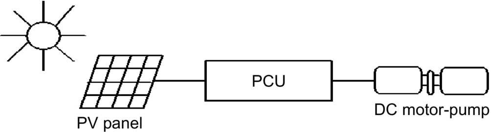
Most PV pump manufacturers include power-conditioning units (PCU) that are used for operating the PV panels close to their MPP over a range of load conditions and varying insolation levels and also for power conversion. DC or AC motor-pump units can be used for PV water pumping. In its simplest form, a solar water pumping system is composed of PV array, PCU, and DC water-pump unit as shown in Fig. 25.24.
In case of lower light levels, high currents can be generated through power conditioning to help in starting the motor-pump units especially for reciprocating positive displacement type pumps with constant torque characteristics, requiring constant current throughout the operating region. In positive displacement type pumps, the torque generated by the pumps depends on the pumping head, friction, pipe diameter, etc. and needs certain level of current to produce the necessary torque. Some systems use electronic controllers to assist starting and operation of the motor under low solar radiation. This is particularly important when using positive displacement pumps. The solar panels generate DC voltage and current. The solar water pumping systems usually have DC or AC pumps. For DC pumps, the PV output can be directly connected to the pump through MPPT, or a DC-DC converter can also be used for interfacing for controlled DC output from PV panels. To feed the AC motors, a suitable interfacing is required for the power conditioning. These PV inverters for the stand-alone applications are very expensive. The aim of power-conditioning equipment is to supply the controlled voltage/current output from the converters/inverters to the motor-pump unit.
These power-conditioning units are also used for operating the PV panels close to their maximum efficiency for fluctuating solar conditions. The speed of the pump is governed by the available driving voltage. Current lower than the acceptable limit will stop the pumping. When the light level increases, the operating point will shift from the MPP leading to the reduction of efficiency. For centrifugal pumps, there is an increase in current at increased speed, and the matching of I-V characteristics is closer for wide range of light intensity levels. For centrifugal pumps, the torque is proportional to the square of speed, and the torque produced by the motors is proportional to the current. Due to decrease in PV current output, the torque from the motor and consequently the speed of the pump are reduced, resulting in decrease in back emf and the required voltage of the motor. Maximum power point tracker can be used for controlling the voltage/current outputs from the PV inverters to operate the PV close to maximum operating point for the smooth operation of motor-pump units. The DC-DC converter can be used for keeping the PV panel output voltage constant and help in operating the solar arrays close to MPP. In the beginning, high starting current is required to produce high starting torque. The PV panels cannot supply this high starting current without adequate power-conditioning equipment like DC-DC converter or by using a starting capacitor. The DC-DC converter can generate the high starting currents by regulating the excess PV array voltage. DC-DC converter can be boost or buck converter.
Brushless DC motor (BDCM) and helical rotor pumps can also be used for PV water pumping [35]. Brushless DC motors are a self-synchronous type of motor characteristics by trapezoidal waveforms for back emf and air flux density. They can operate off a low-voltage DC supply that is switched through an inverter to create a rotating stator field. The current generations of BDCMs use rare-earth magnets on the rotor to give high air gap flux densities and are well suited to solar application. The block diagram of such an arrangement is shown in Fig. 25.25 that consists of PV panels, DC-DC converter, MPPT, and BDCM.

The PV inverters are used to convert the DC output of the solar arrays to the AC quantity so as to run the AC motor-driven pumps. These PV inverters can be variable frequency type, which can be controlled to operate the motors over wide range of loads. The PV inverters may involve impedance matching to match the electric characteristics of the load and array. The motor-pump unit and PV panels operate at their maximum efficiencies. Maximum power point tracker is also used in the power conditioning. To keep the voltage stable for the inverters, the DC-DC converter can be used. The inverter/converter has a capability of injecting high-switch-frequency components, which can lead to the overheating and the losses. So care shall be taken for this. The PV arrays are usually connected in series, parallel, or a combination of series-parallel configurations. The function of power electronic interface, as mentioned before, is to convert the DC power from the array to the required voltage and frequency to drive the AC motors. The motor-pump system load should be such that the array operates close to its MPP at all solar insolation levels. There are mainly three types of solar-powered water pumping systems as shown in Fig. 25.26.

The first system shown in Fig. 25.26A is an imported commercially available unit, which uses a specially wound low-voltage induction-motor-driven submersible pump. Such a low-voltage motor permits the PV array voltage to be converted to AC without using a step-up transformer. The second system, shown in Fig. 25.26B, makes use of a conventional “off-the-shelf” 415 V, 50 Hz induction motor [5]. This scheme needs a step-up transformer to raise inverter output voltage to high voltage. The third scheme as shown in Fig. 25.26C is composed of a DC-DC converter, an inverter that switches at a high frequency, and a mains voltage motor-driven pump. To get the optimum discharge (Q), at a given insolation level, the efficiency of the DC-DC converter and the inverter should be high. So the purpose should be to optimize the output from PV array, motor, and the pump. The principle used here is to vary the duty cycle of a DC-DC converter so that the output voltage is maximum. The DC-DC converter is used to boost the solar array voltage to eliminate the need for a step-up transformer and operate the array at the MPP. The three-phase inverter used in the interface is designed to operate in a variable frequency mode over the range of 20–50 Hz, which is the practical limit for most 50 Hz induction motor applications. Block diagram for frequency control is given in Fig. 25.27.

This inverter would be suitable for driving permanent magnet motors by incorporating additional circuitry for position sensing of the motor's shaft. Also, the inverter could be modified, if required, to produce higher output frequencies for high-speed permanent magnet motors. The inverter has a three-phase full-bridge configuration implemented by MOSFET power transistors.
25.2.4 Grid-Connected PV Systems
The utility interactive inverters not only conditions the power output of the PV arrays but ensures that the PV system output is fully synchronized with the utility power. These systems can be batteryless or with battery backup. Systems with battery storage (or flywheel) provide additional power supply reliability. The grid connection of PV systems is gathering momentum because of various rebate and incentive schemes. This system allows the consumer to feed its own load utilizing the available solar energy, and the surplus energy can be injected into the grid under the energy by back scheme to reduce the payback period. Grid-connected PV systems can become a part of the utility system. The contribution of solar power depends upon the size of system and the load curve of the house. When the PV system is integrated with the utility grid, a two-way power flow is established. The utility grid will absorb excess PV power and will feed the house during nighttime and at instants while the PV power is inadequate. The utility companies are encouraging this scheme in many parts of the world. The grid-connected system can be classified as follows:
• Rooftop application of grid-connected PV system
• Utility-scale large system
For small household PV applications, a roof mounted PV array can be the best option. Solar cells provide an environmentally clean way of producing electricity, and rooftops have always been the ideal place to put them. With a PV array on the rooftop, the solar-generated power can supply residential load. The rooftop PV systems can help in reducing the peak summer load to the benefit of utility companies by feeding the household lighting, cooling, and other domestic loads. The battery storage can further improve the reliability of the system at the time of low insolation level, nighttime, or cloudy days. But the battery storage has some inherent problems like maintenance and higher cost.
For roof-integrated applications, the solar arrays can be either mounted on the roof or directly integrated into the roof. If the roof integration does not allow for an air channel behind the PV modules for ventilation purpose, then it can increase the cell temperature during the operation consequently leading to some energy losses. The disadvantage with the rooftop application is that the PV array orientation is dictated by the roof. In case, when the roof orientation differs from the optimal orientation required for the cells, then the efficiency of the entire system would be suboptimal.
Utility interest in PV has centered on the large grid-connected PV systems. In Germany, the United States, Spain, and in several other parts of the world, some large-scale PV plants have been installed. The utilities are more inclined with large-scale, centralized power supply. The PV systems can be centralized or distributed systems.
Grid-connected PV systems must observe the islanding situation, when the utility supply fails. In case of islanding, the PV generators should be disconnected from mains. PV generators can continue to meet only the local load, if the PV output matches the load. If the grid is reconnected during islanding, transient overcurrents can flow through the PV system inverters, and the protective equipments like circuit breakers may be damaged. The islanding control can be achieved through inverters or via the distribution network. Inverter controls can be designed on the basis of detection of grid voltage, measurement of impedance, frequency variation, or increase in harmonics. Protection shall be designed for the islanding, short circuits, over/under-voltages/currents, grounding, lightening, etc.
The importance of the power generated by the PV system depends upon the time of the day specially when the utility is experiencing the peak load. The PV plants are well suited to summer peaking, but it depends upon the climatic condition of the site. PV systems being investigated for use as peaking stations would be competitive for load management. The PV users can defer their load by adopting load management to get the maximum benefit out of the grid-connected PV plants and feeding more power into the grid at the time of peak load.
The assigned capacity credit is based on the statistical probability with which the grid can meet peak demand [3]. The capacity factor during the peaks is very similar to that of conventional plants, and similar capacity credit can be given for the PV generation except at the times when the PV plants are generating very less power unless adequate storage is provided. With the installation of PV plants, the need of extra transmission lines, transformers can be delayed or avoided. The distributed PV plants can also contribute in providing reactive power support to the grid and reduce burden on VAR compensators.
25.2.4.1 Inverters for Grid-Connected Applications
Power conditioner is the key link between the PV array and mains in the grid-connected PV system. It acts as an interface that converts DC current produced by the solar cells into utility grade AC current. The PV system behavior relies heavily on the power-conditioning unit. The inverters shall produce good quality sine-wave output. The inverter must follow the frequency and voltage of the grid, the inverter has to extract maximum power from the solar cells with the help of MPPT, and the inverter input stage varies the input voltage until the MPP on the I-V curve is found. The inverter shall monitor all the phases of the grid. The inverter output shall be controlled in terms of voltage and frequency variation. A typical grid-connected inverter may use a PWM scheme and operates in the range of 2–20 kHz.
25.2.4.2 Inverter Classifications
The inverters used for the grid interfacing are broadly classified as follows:
• Voltage-source inverters (VSI)
• Current-source inverters (CSI)
The inverters based on the control schemes can be classified as follows:
• Voltage controlled (VC)
The source is not necessarily characterized by the energy source for the system. It is a characteristic of the topology of the inverter. It is possible to change from one source type to another source type by the addition of passive components. In the voltage-source inverter (VSI), the DC side is made to appear to the inverter as a voltage source. The VSIs have a capacitor in parallel across the input, whereas the CSIs have an inductor in series with the DC input. In the CSI, the DC source appears as a current source to the inverter. Solar arrays are fairly good approximation to a current source. Most PV inverters are voltage source even though the PV is a current source. Current-source inverters are generally used for large motor drives though there have been some PV inverters built using a current-source topology. The VSI is more popular with the PWM VSI dominating the sine-wave inverter topologies.
Fig. 25.28A shows a single-phase full-bridge bidirectional VSI with (A) voltage control and phase-shift (δ) control—voltage-controlled voltage-source inverter (VCVSI). The active power transfer from the PV panels is accomplished by controlling the phase angle δ between the converter voltage and the grid voltage. The converter voltage follows the grid voltage. Fig. 25.28B shows the same VSI operated as (B) current controlled (CCVSI). The objective of this scheme is to control active and reactive components of the current fed into the grid using PWM techniques.

25.2.4.3 Inverter Types
Different types are being in use for the grid-connected PV applications such as the following:
• Self-commutated inverter
• Inverter with high-frequency transformer
Line-commutated inverter
The line-commutated inverters are generally used for the electric motor applications. The power stage is equipped with thyristors. The maximum power tracking control is required in the control algorithm for solar application. The basic diagram for a single-phase line-commutated inverter is shown in Fig. 25.29 [2].

The driver circuit has to be changed to shift the firing angle from the rectifier operation (![]() ) to inverter operation (
) to inverter operation (![]() ). Six-pulse or twelve-pulse inverters are used for the grid interfacing, but twelve-pulse inverters produce less harmonics. The thysistor-type inverters require a low-impedance grid interface connection for commutation purpose. If the maximum power available from the grid connection is less than twice the rated PV inverter power, then the line-commutated inverter should not be used [2]. The line-commutated inverters are cheaper but inhibits poor power quality. The harmonics injected into the grid can be large unless taken care of by employing adequate filters. These line-commutated inverters also have poor power factor, poor power quality, and need additional control to improve the power factor. Transformer can be used to provide the electric isolation. To suppress the harmonics generated by these inverters, tuned filters are employed, and reactive power compensation is required to improve the lagging power factor.
). Six-pulse or twelve-pulse inverters are used for the grid interfacing, but twelve-pulse inverters produce less harmonics. The thysistor-type inverters require a low-impedance grid interface connection for commutation purpose. If the maximum power available from the grid connection is less than twice the rated PV inverter power, then the line-commutated inverter should not be used [2]. The line-commutated inverters are cheaper but inhibits poor power quality. The harmonics injected into the grid can be large unless taken care of by employing adequate filters. These line-commutated inverters also have poor power factor, poor power quality, and need additional control to improve the power factor. Transformer can be used to provide the electric isolation. To suppress the harmonics generated by these inverters, tuned filters are employed, and reactive power compensation is required to improve the lagging power factor.
Self-commutated inverter
A switch-mode inverter using pulse-width modulated (PWM) switching control can be used for the grid connection of PV systems. The basic block diagram for this type of inverter is shown in Fig. 25.30. The inverter bridges may consist of bipolar transistors, MOSFET transistors, IGBTs, or gate turn-off thyristors (GTOs), depending upon the type of application. GTOs are used for the higher-power applications, whereas IGBTs can be switched at higher frequencies, that is, 16 kHz, and are generally used for many grid-connected PV applications. Most of the present day inverters are self-commutated sine-wave inverters.

Based on the switching control, the voltage-source inverters can be further classified based on the switching control as follows:
• PWM (pulse-width modulated) inverters
• Square-wave inverters
• Single-phase inverters with voltage cancellations
• Programmed harmonic elimination switching
• Current-controlled modulation
Inverter with high-frequency transformer
The 50 Hz transformer for a standard PV inverter with PWM switching scheme can be very heavy and costly. While using frequencies more than 20 kHz, a ferrite core transformer can be a better option [2]. A circuit diagram of a grid-connected PV system using high-frequency transformer is shown in Fig. 25.31.

The capacitor on the input side of high-frequency inverter acts as the filter. The high-frequency inverter with PWM is used to produce a high-frequency AC across the primary winding of the high-frequency transformer. The secondary voltage of this transformer is rectified using high-frequency rectifier. The DC voltage is interfaced with a thyristor inverter through a low-pass inductor filter and hence connected to the grid. The line current is required to be sinusoidal and in phase with the line voltage. To achieve this, the line voltage (V1) is measured to establish the reference waveform for the line current IL⁎. This reference current IL⁎ multiplied by the transformer ratio gives the reference current at the output of a high-frequency inverter. The inverter output can be controlled using current control technique [36]. These inverters can be with low-frequency transformer isolation or high-frequency transformer isolation. The low-frequency (50–60 Hz) transformer of a standard inverter with PWM is a very heavy and bulky component. For residential grid-interactive rooftop inverters below 3 kW rating, high-frequency transformer isolation is often preferred.
Other PV inverter topologies
In this section, some of the inverter topologies discussed in various research papers have been discussed.
Multilevel converters
Multilevel converters can be used with large PV systems where multiple PV panels can be configured to create voltage steps. These multilevel voltage-source converters can synthesize the AC output terminal voltage from different level of DC voltages and can produce staircase waveforms. This scheme involves less complexity and needs less filtering. One of the schemes (half-bridge diode-clamped three-level inverter [37]) is given in Fig. 25.32. There is no transformer in this topology. Multilevel converters can be beneficial for large systems in terms of cost and efficiency. Problems associated with shading and malfunction of PV units need to be addressed.

The utilization of cascaded multilevel inverter (CMLI) in high-voltage and high-power PV energy conversion has been recently increased [38–40]. CMLI consists of a number of inverter units that are fed by isolated PV array [38]. Each unit utilizes low-voltage components, and the final output voltage is synthesized by combining all units in series. This topology has modular characteristic, since all the units are similar and have the same control strategy. This modularity feature makes it very easy to replace any faulty unit. Without discontinuing the load, it is also possible to bypass the faulty module by adopting a proper control technique [41].
Fig. 25.33 shows a five-level cascaded H-bridge inverter. Each inverter arm consists of a number of H-bridge units whose outputs are connected in series. Each unit comprises four switches (S1–S4) and one DC input supply (Vdc). The basic H-bridge unit shown in Fig. 25.34 is able to produce three voltage levels (−Vdc, 0, and Vdc). The output voltage and switching logic of this H-bridge unit is shown in Table 25.2.


Table 25.2
Switching logic of an H-bridge unit
| Vout | Turn on switches |
| Vdc | S1, S4 |
| 0 | S1, S3 |
| S2, S4 | |
| −Vdc | S2, S3 |

In Fig. 25.34, each phase arm contains two series-connected units. The output line voltages comprises five levels (−2 Vdc, −Vdc, 0, Vdc, and 2 Vdc). If the number of units in each phase arm is “u,” then the number of levels in the line voltage is (l=2u+1). All possible switching combinations for a five-level H-bridge inverter are presented in Table 25.3.
Table 25.3
All possible switching combination for various output levels of a 5-level CHB inverter
 |
U1 | U2 | U1 | U2 | ||||||
| Vo,U1 | Vo,U2 | S1 | S2 | S3 | S4 | S1 | S2 | S3 | S4 | |
| 2Vdc | Vdc | Vdc | 1 | 0 | 0 | 1 | 1 | 0 | 0 | 1 |
| Vdc | Vdc | 0 | 1 | 0 | 0 | 1 | 1 | 0 | 1 | 0 |
| Vdc | 0 | 1 | 0 | 0 | 1 | 0 | 1 | 0 | 1 | |
| 0 | Vdc | 1 | 0 | 1 | 0 | 1 | 0 | 0 | 1 | |
| 0 | Vdc | 0 | 1 | 0 | 1 | 1 | 0 | 0 | 1 | |
| 0 | Vdc | −Vdc | 1 | 0 | 0 | 1 | 0 | 1 | 1 | 0 |
| 0 | 0 | 1 | 0 | 1 | 0 | 1 | 0 | 1 | 0 | |
| 0 | 0 | 1 | 0 | 1 | 0 | 0 | 1 | 0 | 1 | |
| 0 | 0 | 0 | 1 | 0 | 1 | 1 | 0 | 1 | 0 | |
| 0 | 0 | 0 | 1 | 0 | 1 | 0 | 1 | 0 | 1 | |
| −Vdc | Vdc | 0 | 1 | 1 | 0 | 1 | 0 | 0 | 1 | |
| −Vdc | 0 | −Vdc | 1 | 0 | 1 | 0 | 0 | 1 | 1 | 0 |
| 0 | −Vdc | 0 | 1 | 0 | 1 | 0 | 1 | 1 | 0 | |
| −Vdc | 0 | 0 | 1 | 1 | 0 | 1 | 0 | 1 | 0 | |
| −Vdc | 0 | 0 | 1 | 1 | 0 | 0 | 1 | 0 | 1 | |
| −2Vdc | −Vdc | −Vdc | 0 | 1 | 1 | 0 | 0 | 1 | 1 | 0 |

A three-phase “l”-level CHB MLI needs 6(l−1) switching devices. No additional diodes are needed, except the antiparallel diodes in the switches. The current and voltage ratings of all switching devices are similar in case of symmetrical condition. In case of PV energy conversion, the input DC supplies of the H-bridge units are replaced by the PV arrays [42–45].
Non-insulated voltage source
In this scheme [46], string of low-voltage PV panels or one high-voltage unit can be coupled with the grid through DC-to-DC converter and voltage-source inverter. This topology is shown in Fig. 25.35. PWM switching scheme can be used to generate AC output. Filter has been used to reject the switching components.

Non-insulated current source
This type of configuration is shown in Fig. 25.36. Noninsulated current-source inverters [46] can be used to interface the PV panels with the grid. This topology involves low cost, which can provide better efficiency. Appropriate controller can be used to reduce current harmonics.

Buck converter with half-bridge transformer link
PV panels are connected to grid via buck converter and half bridge as shown in Fig. 25.37. In this, high-frequency PWM switching has been used at the low-voltage PV side to generate an attenuated rectified 100 Hz sine-wave current waveform [47]. Half-wave bridge is utilized to convert this output to 50 Hz signal suitable for grid interconnection. To step up the voltage, the transformer has also been connected before the grid connection point.

Flyback converter
This converter topology steps up the PV voltage to DC bus voltage. Pulse-width-modulation-operated converter has been used for grid connection of PV system (Fig. 25.38). This scheme is less complex and has less number of switches. Flyback converters can be beneficial for remote areas due to less complex power-conditioning components.

Interface using paralleled PV panels
Low-voltage AC bus scheme [48] can be comparatively efficient and cheaper option. One of the schemes is shown in Fig. 25.39. A number of smaller PV units can be paralleled together and then connected to combine single low-frequency transformer. In this scheme, the PV panels are connected in parallel rather than series to avoid problems associated with shading or malfunction of one of the panels in series connection.

25.2.4.4 Power Control through PV Inverters
The system shown in Fig. 25.40 shows control of power flow onto the grid [49]. This control can be an analog or a microprocessor system. This control system generates the waveforms and regulates the waveform amplitude and phase to control the power flow between the inverter and the grid. The grid-interfaced PV inverters, voltage-controlled VSI (VCVSI), and current-controlled VSI (CCVSI) have the potential of bidirectional power flow. They not only can feed the local load but also can export the excess active and reactive power to the utility grid. An appropriate controller is required in order to avoid any error in power export due to errors in synchronization, which can overload the inverter.

There are advantages and limitations associated with each control mechanism. For instance, VCVSIs provide voltage support to the load (here, the VSI operates as a voltage source), while CCVSIs provide current support (here, the VSI operates as a current source). The CCVSI is fast in response compared with the VCVSI, as its power flow is controlled by the switching instant, whereas in the VCVSI the power flow is controlled by adjusting the voltage across the decoupling inductor. Active and reactive powers are controlled independently in the CCVSI but are coupled in the VCVSI. Generally, the advantages of one type of VSI are considered as a limitation of the other type [50].
Fig. 25.41 shows the simplified/equivalent schematic diagram of a VCVSI. For the following analysis, it is assumed that the output low-pass filters (Lf and Cf) of VSIs will filter out high-order harmonics generated by PWMs. The decoupling inductor (Xm) is an essential part of any VCVSI as it makes the power flow control possible. In a VCVSI, the power flow of the distributed generation system (DGS) is controlled by adjusting the amplitude and phase (power angle (δ)) of the inverter output voltage with respect to the grid voltage. Hence, it is important to consider the proper sizing of the decoupling inductor and the maximum power angle to provide the required power flow when designing VCVSIs. The phasor diagram of a simple grid-inverter interface with a first-order filter is shown in Fig. 25.42.


Referring to Fig. 25.41, the fundamental grid current (Ig) can be expressed by Eq. (25.7):

where Vg and Vc are, respectively, the grid and the VCVSI's fundamental voltages and Xm is the decoupling inductor impedance. Using per-unit values (![]() ,
, ![]() , and
, and ![]() ) where Vbase, Zbase, and Sbase are the base voltage, impedance, and complex power values, respectively, the grid apparent power can be expressed as Eq. (25.8):
) where Vbase, Zbase, and Sbase are the base voltage, impedance, and complex power values, respectively, the grid apparent power can be expressed as Eq. (25.8):
Using per-unit values, the complex power of the VCVSI and decoupling inductor are
where Sgpu, Scpu, and Sxpu are per-unit values of the grid, VCVSI, and decoupling inductor apparent power, respectively, and Vgpu is the per-unit value of the grid voltage.
Fig. 25.43 shows the equivalent schematic diagram of a CCVSI. As a CCVSI controls the current flow using the VSI switching instants, it can be modeled as a current source, and there is no need for a decoupling inductor (Fig. 25.43). As the current generated from the CCVSI can be controlled independently from the AC voltage, the active and reactive power controls are decoupled. Hence, unity power factor operation is possible for the whole range of the load. This is one of the main advantages of CCVSIs.

As the CCVSI is connected in parallel to the DGS, it follows the grid voltage. Fig. 25.44 shows the phasor diagram of a CCVSI-based DGS in the presence of an inductive load (considering the same assumption as VCVSI section). Fig. 25.44 shows that when the grid voltage increases, the load's active power consumption, which is supplied by the grid, increases and the CCVSI compensates the increase in the load reactive power demand. In this case, the CCVSI maintains grid supply at unity power factor, keeping the current phase delay with respect to the grid voltage at a fixed value (θ). Therefore, the CCVSI cannot maintain the load voltage in the presence of a DGS without utilizing extra hardware and control mechanisms. This limitation on load voltage stabilization is one of the main drawbacks of CCVSI-based DGS.

Assuming the load active current demand is supplied by the grid (reactive power support function), the required grid current can be rewritten as follows:

where SL is the demanded load apparent power. For grid power conditioning, it is preferred that the load operate at unity power factor. Therefore, the CCVSI must provide the remainder of the required current in Eq. (25.12):
For demand side management (DSM), it is desirable to supply the active power by the RES, where excess energy from the RES is injected into the DGS. The remaining load reactive power will be supplied by the CCVSI. Hence, Eq. (25.12) can be rewritten as Eq. (25.13):

When using a voltage controller for grid-connected PV inverter, it has been observed that a slight error in the phase of synchronizing waveform can grossly overload the inverter whereas a current controller is much less susceptible to voltage phase shifts [49]. Due to this reason, the current controllers are better suited for the control of power export from the PV inverters to the utility grid since they are less sensitive to errors in synchronizing sinusoidal voltage waveforms.
A prototype current-controlled-type power-conditioning system has been developed by the first author and tested on a weak rural feeder line at Kalbarri in Western Australia [51]. The choice may be between additional conventional generating capacities at a centralized location and adding smaller distributed generating capacities using RES like PV. The latter option can have a number of advantages like as follows:
• The additional capacity is added wherever it is required without adding additional power distribution infrastructure. This is a critical consideration where the power lines and transformers are already at or close to their maximum ratings.
• The power-conditioning system can be designed to provide much more than just a source of real power, for minimal extra cost. A converter providing real power needs only a slight increase in ratings to handle significant amounts of reactive or even harmonic power. The same converter that converts DC PV power to AC power can simultaneously provide the reactive power support to the week utility grid.
The block diagram of the power-conditioning system used in the Kalbarri project has been shown in Fig. 25.45. This CCVSI operates with a relatively narrow switching frequency band near 10 kHz. The control diagram indicates the basic operation of the power-conditioning system. The two outer control loops operate to independently control the real and reactive power flow from the PV inverter. The real power is controlled by an outer MPPT algorithm with an inner DC link voltage control loop providing the real current magnitude request Ip⁎, and hence, the real power export through PV converter is controlled through the DC link voltage regulation. The DC link voltage is maintained at a reference value by a PI control loop, which gives the real current reference magnitude as its output. At regular intervals, the DC link voltage is scanned over the entire voltage range to check that the algorithm is operating on the absolute MPP and is not stuck around a local MPP. During the night, the converter can still be used to regulate reactive power of the grid-connected system although it cannot provide active power. During this time, the PI controller maintains a minimum DC link voltage to allow the power-conditioning system to continue to operate, providing the necessary reactive power.

The AC line voltage regulation is provided by a separate reactive power control, which provides the reactive current magnitude reference IQ⁎. The control system has a simple transfer function, which varies the reactive power command in response to the AC voltage fluctuations. Common to the outer real and reactive power control loops is an inner higher bandwidth zero average current error (ZACE) current control loop. Ip⁎ is in phase with the line voltages, and IQ⁎ is at 90° to the line voltage. These are added together to give one (per phase) sinusoidal converter current reference waveform (Iac⁎). The CCVSI control consists of analog and digital circuitry that acts as a ZACE transconductance amplifier in converting Iac⁎ into AC power currents [52].
25.2.4.5 System Configurations
The utility compatible inverters are used for power conditioning and synchronization of PV output with the utility power. In general, four types of batteryless grid-connected PV system configurations have been identified:
• Multiple string DC/DC converter with single-output inverter
• Multiple string inverter
• Module-integrated inverter
Central plant inverter
In the central plant inverter, usually a large inverter is used to convert DC power output of PV arrays to AC power. In this system, the PV modules are serially stringed to form a panel (or string), and several such panels are connected in parallel to a single DC bus. The block diagram of such a scheme is shown in Fig. 25.46.

Multiple string DC/DC converter
In multiple string DC/DC converter, as shown in Fig. 25.47, each string will have a boost DC/DC converter with transformer isolation. There will be a common DC link, which feeds a transformerless inverter.

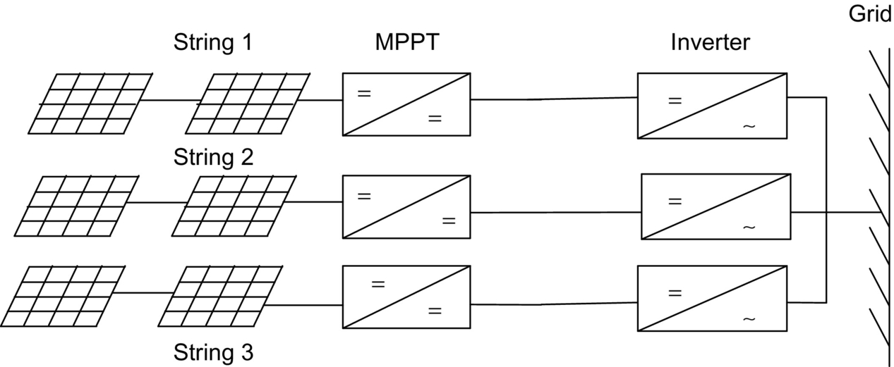
Multiple string inverters
Fig. 25.48 shows the block diagram of multiple string inverter system. In this scheme, several modules are connected in series on the DC side to form a string. The output from each string is converted to AC through a smaller individual inverter. Many such inverters are connected in parallel on the AC side. This arrangement is not badly affected by the shading of the panels. It is also not seriously affected by inverter failure.
Module integrated inverter
In the module-integrated inverter system (Fig. 25.49), each module (typically 50–300 W) will have a small inverter. No cabling is required. It is expected that high volume of small inverters will bring down the cost.

25.2.4.6 Grid-Compatible Inverters Characteristics
The characteristics of the grid-compatible inverters are as follows:
• Power factor
• Frequency control
• Harmonic output
• Synchronization
• Fault current contribution
• DC current injection
• Protection
The response time of the inverters shall be extremely fast and governed by the bandwidth of the control system. The absence of rotating mass and use of semiconductor switches allow inverters to respond in millisecond time frame. The power factor of the inverters is traditionally poor due to displacement power factor and the harmonics. But with the latest development in the inverter technology, it is possible to maintain the power factor close to unity. The converters/inverters have the capability of creating large voltage fluctuation by drawing reactive power from the utility rather than supplying [53]. With proper control, inverters can provide voltage support by importing/exporting reactive power to push/pull toward a desired set point. This function would be of more use to the utilities as it can assist in the regulation of the grid system at the domestic consumer level.
Frequency of the inverter output waveshape is locked to the grid. Frequency bias is where the inverter frequency is deliberately made to run at 53 Hz. When the grid is present, this will be pulled down to the nominal 50 Hz. If the grid fails, it will drift upward toward 53 Hz and trip on overfrequency. This can help in preventing islanding.
Harmonics output from the inverters have been very poor traditionally. Old thyristor-based inverters are operated with slow switching speeds and could not be pulse-width modulated. This resulted in inverters known as 6-pulse or 12-pulse inverters. The harmonics so produced from the inverters can be injected into the grid, resulting in losses, heating of appliances, tripping of protection equipments, and poor power quality. The number of pulses is being the number of steps in a sine-wave cycle. With the present advent in the power electronics technology, the inverter controls can be made very well. Pulse-width-modulated inverters produce high-quality sine waves. The harmonic levels are very low and can be lower than the common domestic appliances. If the harmonics are present in the grid voltage waveform, harmonic currents can be induced in the inverter. These harmonic currents, particularly those generated by a voltage-controlled inverter, will in fact help in supporting the grid. These are good harmonic currents. This is the reason that the harmonic current output of inverters must be measured onto a clean grid source so that the only harmonics being produced by the inverters are measured.
Synchronization of inverter with the grid is performed automatically and typically uses zero-crossing detection on the voltage waveform. An inverter has no rotating mass and hence has no inertia. Synchronization does not involve the acceleration of a rotating machine. Consequently, the reference waveforms in the inverter can be jumped to any point required within a sampling period. If phase-locked loops are used, it could take up a few seconds. Phase-locked loops are used to increase the immunity to noise. This allows the synchronization to be based on several cycles of zero-crossing information. The response time for this type of locking will be slower.
Photovoltaic panels produce a current that is proportional to the amount of light falling on them. The panels are normally rated to produce 1000 W/m2 at 25°C. Under these conditions, the short-circuit current possible from these panels is typically only 20% higher than the nominal current, whereas it is extremely variable for wind. If the solar radiation is low, then the maximum current possible under short circuit is going to be less than the nominal full-load current. Consequently, PV systems cannot provide the short-circuit capacity to the grid. If a battery is present, the fault current contribution is limited by the inverter. With the battery storage, it is possible for the battery to provide the energy. However, inverters are typically limited between 100% and 200% of nominal rating under current limit conditions. The inverter needs to protect itself against the short circuits because the power electronic components will typically be destroyed before a protection device like circuit breaker trips.
In case of inverter malfunction, inverters have the capability to inject the DC components into the grid. Most utilities have guidelines for this purpose. A transformer shall be installed at the point of connection on the AC side to prevent DC from entering into the utility network. The transformer can be omitted when a DC detection device is installed at the point of connection on the AC side in the inverter. The DC injection is essentially caused by the reference or power electronic device producing a positive half cycle that is different from the negative half cycle resulting in the DC component in the output. If the DC component can be measured, it can then be added into the feedback path to eliminate the DC quantity.
Protection requirements
A minimum requirement to facilitate the prevention of islanding is that the inverter energy system protection operates and isolates the inverter energy system from the grid if
• Undervoltage,
• Overfrequency,
• Underfrequency exist.
These limits may be either factory set or site programmable. The protection voltage operating points may be set in a narrower band if required, for example, 220–260 V. In addition to the passive protection detailed above and to prevent the situation where islanding may occur because multiple inverters provide a frequency reference for one another, inverters must have an accepted active method of islanding prevention following grid failure, for example, frequency drift and impedance measurement. Inverter controls for islanding can be designed on the basis of detection of grid voltage, measurement of impedance, frequency variation, or increase in harmonics. This function must operate to force the inverter output outside the protection tolerances specified previously, thereby resulting in isolation of the inverter energy system from the grid. The maximum combined operation time of both passive and active protections should be 2 s after grid failure under all local load conditions. If frequency shift is used, it is recommended that the direction of shift be down. The inverter energy system must remain disconnected from the grid until the reconnection conditions are met. Some inverters produce high-voltage spikes, especially at light load, which can be dangerous for the electronic equipment. IEEE P929 gives some idea about the permitted voltage limits.
If the inverter energy system does not have the above frequency features, the inverter must incorporate an alternate anti-islanding protection feature that is acceptable to the relevant electricity distributor. If the protection function above is to be incorporated in the inverter, it must be type tested for compliance with these requirements and accepted by the relevant electricity distributor. Otherwise, other forms of external protection relaying are required that have been type tested for compliance with these requirements and approved by the relevant electricity distributor. The inverter shall have adequate protection against short circuit, other faults, and overheating of inverter components.
25.3 Power Electronics for Wind Power Systems
In the rural United States, the first windmill was commissioned in 1890 to generate electricity. Today, large wind generators are competing with utilities in supplying clean power economically. The average wind turbine size has been 300–600 kW until recently. The new wind generators of 1–3 MW have been developed and are being installed worldwide, and prototype of even higher capacity is under development. Improved wind turbine designs and plant utilization have resulted in significant reduction in wind energy generation cost from 35 cents/kWh in 1980 to less than 5 cents/kWh in 1999, in locations where wind regime is favorable. At this generation cost, wind energy has become one of the least cost power sources. Main factors that have contributed to the wind power technology development are as follows:
• High-strength fiber composites for manufacturing large low-cost blades
• Variable-speed operation of wind generators to capture maximum energy
• Advancement in power electronics and associated cost
• Improved plant operation and efficiency
• Economy of scale due to the availability of large wind generation plants
• Accumulated field experience improving the capacity factor
• Computer prototyping by accurate system modeling and simulation
Table 25.4 is for wind sites with average annual wind speed of 7 m/s at 30 m hub height. Since the 1980s, wind technology capital costs have reduced by 80% worldwide. Operation and maintenance costs have declined by 80%, and the availability factor of grid-connected wind plants has increased to 95%. At present, the capital cost of wind generator plants has dropped to about $600/kW, and the electricity generation cost has reduced to 6 cents/kWh. It is expected to reduce the generation cost below 4 cents/kWh. Keeping this in view, the wind generation is going to be highly competitive with the conventional power plants. In Europe, the United States, and Asia, the wind power generation is increasing rapidly, and this trend is going to continue due to economic viability of wind power generation.
Table 25.4
Wind power technology developments
| 1980 | 1999 | Future | |
| Cost per kilowatt-hour | $0.35–0.40 | $0.05–0.07 | |
| Capital cost per kilowatt | $2000–3000 | $500–700 | |
| Operating life | 5–7 years | 20 years | 30 years |
| Capacity factor (average) | 15% | 25%–30% | |
| Availability | 50%–65% | 95% | |
| Wind turbine unit size range | 50–150 kW | 300–1000 kW | 500–2000 kW |

The technical advancement in power electronics is playing an important part in the development of wind power technology. The contribution of power electronics in control of fixed-speed/variable-speed wind turbines and interfacing to the grid is of extreme importance. Because of the fluctuating nature of wind speed, the power quality and reliability of the wind-based power system needs to be evaluated in detail. Appropriate control schemes require power conditioning.
25.3.1 Basics of Wind Power
The ability of a wind turbine to extract power from wind is a function of three main factors:
• Power curve of the machine
• Ability of the machine to respond to wind perturbations
The mechanical power produced by a wind turbine is given by
The power from the wind is a cubic function of wind speed. The curve for power coefficient Cp and λ is required to infer the value of Cp for λ based on wind speed at that time.
Where tip-speed ratio, ![]() , ρ=air density, Kg m
, ρ=air density, Kg m![]() , Cp=power coefficient, A=wind turbine rotor swept area, m2, and U=wind speed in meters per second.
, Cp=power coefficient, A=wind turbine rotor swept area, m2, and U=wind speed in meters per second.
The case of a variable-speed wind turbine with a pitch mechanism that alters the effective rotor dynamic efficiency can be easily considered if an appropriate expression for Cp as a function of the pitch angle is applied. The power curve of a typical wind turbine is given in Fig. 25.50 as a function of wind speed.

The Cp–λ curve for 150 kW windmaster machine is given in Fig. 25.51, which has been inferred from the power curve of the machine. The ratio of shaft power to the available power in the wind is the efficiency of conversion, known as the power coefficient Cp:


The power coefficient is a function of turbine blade tip-speed to wind-speed ratio (β). A tip-speed ratio of 1 means the blade tips are moving at the same speed as the wind, and when β is 2, the tips are moving at twice the speed of the wind and so on [55]. Solidity (σ) is defined as the ratio of the sum of the width of all the blades to the circumference of the rotor. Hence,
where N=number of blades and d=width of the blades.
The power from a wind turbine doubles as the area swept by the blades doubles. But doubling of the wind speed increases the power output eight times. Fig. 25.52 gives a family of power curves for a wind turbine. If the loading of the turbine is controlled such that the operating point is along the maximum power locus at different wind speeds, then the wind energy system will be more efficient.

25.3.1.1 Types of Wind Turbines
There are two types of wind turbines available Fig. 25.53:

• Horizontal-axis wind turbines (HAWTs)
• Vertical-axis wind turbines (VAWTs)
Vertical-axis wind turbines (VAWTs) have an axis of rotation that is vertical, and so, unlike the horizontal wind turbines, they can capture winds from any direction without the need to reposition the rotor when the wind direction changes (without a special yaw mechanism). Vertical-axis wind turbines were also used in some applications as they have the advantage that they do not depend on the direction of the wind. It is possible to extract power relatively easier. But there are some disadvantages such as no self-starting system, smaller power coefficient than obtained in the horizontal-axis wind turbines, strong discontinuation of rotations due to periodic changes in the lift force, and the regulation of power that is not yet satisfactory.
The horizontal-axis wind turbines are generally used. Horizontal-axis wind turbines are, by far, the most common design. There are a large number of designs commercially available ranging from 50 W to 4.5 MW. The number of blades ranges from one to many in the familiar agriculture windmill. The best compromise for electricity generation, where high rotational speed allows the use of a smaller and cheaper electric generator, is two or three blades. The mechanical and aerodynamic balance is better for three-bladed rotor. In small wind turbines, three blades are common. Multiblade wind turbines are used for water pumping on farms.
Based on the pitch control mechanisms, the wind turbines can also be classified as follows:
• Variable-pitch wind turbines
Different manufacturers offer fixed-pitch and variable-pitch blades. Variable pitch is desirable on large machines because the aerodynamic loads on the blades can be reduced and when used in fixed-speed operation they can extract more energy. But necessary mechanisms require maintenance, and for small machines, installed in remote areas, fixed pitch seems more desirable and economical. In some machines, power output regulation involves yawing blades so that they no longer point into the wind. One such system designed in Western Australia has a tail that progressively tilts the blades in a vertical plane so that they present a small surface to the wind at high speeds.
The active power of a wind turbine can be regulated either by designing the blades to go into an aerodynamic stall beyond the designated wind speed or by feathering the blades out of the wind, which results in reducing excess power using a mechanical and electric mechanism. Recently, an active stall has been used to improve the stability of wind farms. This stall mechanism can prevent power deviation from gusty winds to pass through the drivetrain [56].
Horizontal-axis wind turbines can be further classified into fixed speed (FS) or variable speed (VS). The FS wind turbine (FSWT) generator is designed to operate at maximum efficiency while operating at a rated wind speed. In this case, the optimum tip-speed ratio is obtained for the rotor airfoil at a rated wind speed. For a VS wind turbine (VSWT) generator, it is possible to obtain optimum wind speed at different wind speeds. Hence, this enables the VS wind turbine to increase its energy capture. The general advantages of a VSWT are summarized as follows:
• VSWTs are more efficient than the FSWTs.
• At low wind speeds, the wind turbines can still capture the maximum available power at the rotor, hence increasing the possibility of providing the rated power for wide speed range.
25.3.1.2 Types of Wind Generators
Schemes based on permanent magnet synchronous generators (PMSG) and induction generators are receiving close attention in wind power applications because of their qualities such as ruggedness, low cost, manufacturing simplicity, and low-maintenance requirements. Despite many positive features over the conventional synchronous generators, the PMSG was not being used widely [22]. However, with the recent advent in power electronics, it is now possible to control the variable voltage, variable frequency output of PMSG. The permanent magnet machine is generally favored for developing new designs, because of higher efficiency and the possibility of a rather smaller diameter. These PMSG machines are now being used with variable-speed wind machines.
In large power system networks, synchronous generators are generally used with fixed-speed wind turbines. The synchronous generators can supply both the active and reactive power, and their reactive power flow can be controlled. The synchronous generators can operate at any power factor. For the induction generator, driven by a wind turbine, it is a well-known fact that it can deliver only active power while consuming reactive power.
Synchronous generators with high power rating are significantly more expensive than induction generators of similar size. Moreover, direct-connected synchronous generators have the limitation of rotational speed being fixed by the grid frequency. Hence, fluctuation in the rotor speed due to wind gusts leads to higher torque in high power output fluctuations and the derived train. Therefore, in grid-connected application, synchronous generators are interfaced via power converters to the grid. This also allows the synchronous generators to operate wind turbines in VS, which makes gearless operation of the VSWT possible.
The squirrel-cage induction generators are widely used with the fixed-speed wind turbines. In some applications, wound rotor induction generators have also been used with adequate control scheme for regulating speed by external rotor resistance. This allows the shape of the torque-slip curve to be controlled to improve the dynamics of the drivetrain. In case of PMSG, the converter/inverter can be used to control the variable voltage, variable frequency signal of the wind generator at varying wind speed. The converter converts this varying signal to the DC signal, and the output of converter is converted to AC signal of desired amplitude and frequency.
The induction generators are not locked to the frequency of the network. The cyclic torque fluctuations at the wind turbine can be absorbed by very small change in the slip speed. In case of the capacitor-excited induction generators, they obtain the magnetizing current from capacitors connected across its output terminals [55,57,58].
To take advantage of VSWTs, it is necessary to decouple the rotor speed and the grid frequency. There are different approaches to operate the VSWT within a certain operational range (cut-in and cut-out wind speed). One of the approaches is dynamic slip control, where the slip is allowed to vary up to 10% [59]. In these cases, doubly-fed induction generators (DFIG) are used (Fig. 25.54). One limitation is that DFIG require reactive power to operate. As it is not desired that the grid supply this reactive power, these generators are usually equipped with capacitors. A gearbox forms an essential component of the wind turbine generator (WTG) using induction generators. This results in the following limitations:
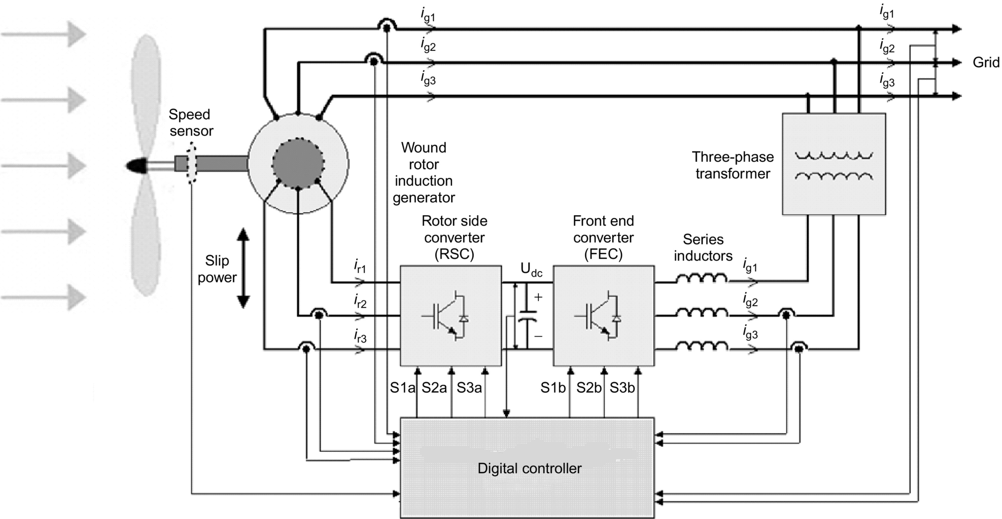
• Additional cost
• Additional losses
With the emergence of large wind power generation, increased attention is being directed toward wound rotor induction generators (WRIG) controlled from the rotor side for variable-speed constant-frequency (VSCF) applications. A wound rotor induction generator has a rotor containing a three-phase winding. These windings are made accessible to the outside via slip rings. The main advantages of a wound rotor induction generator for VSCF applications are as follows:
• Easier generator torque control using rotor current control.
• Smaller generator capacity as the generated power can be accessed from the stator and from the rotor. Usually, the rotor power is proportional to the slip speed (shaft speed-synchronous speed). Consequently, smaller rotor power converters are required. The frequency converter in the rotor (inverter) directly controls the current in the rotor winding, which enables the control of the whole generator output. The power electronic converters generally used are rated at 20%–30% of the nominal generator power.
• Fewer harmonics exist because control is in the rotor while the stator is directly connected to the grid.
If the rotor is short-circuited (making it the equivalent of a cage rotor induction machine), the speed is primarily determined by the supply frequency, and the nominal slip is within 5%. The mechanical power input (PTURBINE) is converted into stator electric power output (PSTATOR) and is fed to the AC supply. The rotor power loss, being proportional to the slip speed, is commonly referred to as the slip power (PROTOR). The possibility of accessing the rotor in a doubly fed induction generator makes a number of configurations possible. These include slip power recovery using a cycloconverter, which converts the ac voltage of one frequency to another without an intermediate DC link [60–62], or back-to-back inverter configurations [63,64].
Using voltage-source inverters (VSIs) in the rotor circuit, the rotor currents can be controlled at the desired phase, frequency, and magnitude. This enables reversible flow of active power in the rotor, and the system can operate in subsynchronous and supersynchronous speeds, both in motoring and generating modes. The DC link capacitor acts as a source of reactive power, and it is possible to supply the magnetizing current, partially or fully, from the rotor side. Therefore, the stator-side power factor can also be controlled. Using vector control techniques, the active and reactive powers can be controlled independently, and hence, fast dynamic performance can also be achieved.
The converter used at the grid interface is termed as the line-side converter or the front-end converter (FEC). Unlike the rotor-side converter, this operates at the grid frequency. Flow of active and reactive powers is controlled by adjusting the phase and amplitude of the inverter terminal voltage with respect to the grid voltage. Active power can flow either to the grid or to the rotor circuit depending on the mode of operation. By controlling the flow of active power, the DC bus voltage is regulated within a small band. Control of reactive power enables unity power factor operation at the grid interface. In fact, the FEC can be operated at a leading power factor, if it is so desired. It should be noted that, since the slip range is limited, the DC bus voltage is less in this case when compared with the stator side control. A transformer is therefore necessary to match the voltage levels between the grid and the DC side of the FEC. With a PWM converter in the rotor circuit, the rotor currents can be controlled at the desired phase, frequency, and magnitude. This enables reversible flow of active power in the rotor, and the system can operate in subsynchronous and supersynchronous speeds, both in motoring and generating modes (Fig. 25.55).

25.3.2 Types of Wind Power Systems
Wind power systems can be classified as follows:
• Hybrid
• Grid-connected
25.3.3 Stand-alone Wind Power Systems
Stand-alone wind power systems are being used for the following purposes in remote-area power systems:
• Household power supply
25.3.3.1 Battery Charging with Stand-alone Wind Energy System
The basic elements of a stand-alone wind energy conversion system are as follows:
• Tower
• Charge control system
• Battery storage
• Distribution network
In remote-area power supply, an inverter and a diesel generator are more reliable and sophisticated systems. Most small isolated wind energy systems use batteries as a storage device to level out the mismatch between the availability of the wind and the load requirement. Batteries are a major cost component in an isolated power system.
25.3.3.2 Wind Turbine Charge Controller
The basic block diagram of a stand-alone wind generator and battery charging system is shown in Fig. 25.56.
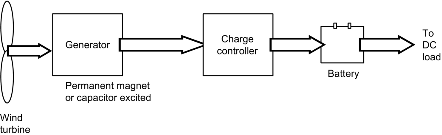
The function of charge controller is to feed the power from the wind generator to the battery bank in a controlled manner. In the commonly used permanent magnet generators, this is usually done by using the controlled rectifiers [65]. The controller should be designed to limit the maximum current into the battery, reduce charging current for high battery SOC, and maintain a trickle charge during full SOC periods.
25.3.4 Wind-Diesel Hybrid Systems
The details of hybrid systems are already covered in Section 25.2.4. Diesel systems without batteries in remote areas are characterized by poor efficiency, high maintenance, and fuel costs. The diesel generators must be operated above a certain minimum load level to reduce cylinder wear and tear due to incomplete combustion. It is a common practice to install dump loads to dissipate extra energy. More efficient systems can be devised by combining the diesel generator with a battery-inverter subsystem and incorporating RES, such as wind/solar where appropriate. An integrated hybrid energy system incorporating a diesel generator, wind generator, battery or flywheel storage, and inverter will be cost-effective at many sites with an average daily energy demand exceeding 25 kWh [66]. These hybrid energy systems can serve as a minigrid as a part of distributed generation rather than extending the grid to the remote rural areas. The heart of the hybrid system is a high-quality sine-wave inverter, which can also be operated in reverse as battery charger. The system can cope with loads ranging from zero (inverter only operation) to approximately three times greater capacity (inverter and diesel operating in parallel).
Decentralized form of generation can be beneficial in remote-area power supply. Due to high cost of PV systems, problems associated with storing electricity over longer periods (like maintenance difficulties and costs), wind turbines can be a viable alternative in hybrid systems. Systems with battery storage provide better reliability. Wind power penetration can be high enough to make a significant impact on the operation of diesel generators.
High wind penetration also poses significant technical problems for the system designer in terms of control and transient stability [29]. In earlier stages, wind-diesel systems were installed without assessing the system behavior due to the lack of design tools/software. With the continual research in this area, there is now software available to assist in this process. Wind-diesel technology has now matured due to research and development in this area. Now, there is a need to utilize this knowledge into cost-effective and reliable hybrid systems [67]. In Western Australia, dynamic modeling of wind-diesel hybrid system has been developed in Curtin/MUERI, supported by the Australian Cooperative Research Centre for Renewable Energy (ACRE) program 5.21.
25.3.5 Grid-Connected Wind Energy Systems
Small-scale wind turbines, connected to the grid (weak or strong grid), have been discussed here. Wind-diesel systems have been getting attention in many remote parts of the world lately. Remote-area power supplies are characterized by low inertia, low damping, and poor reactive power support. Such weak power systems are more susceptible to sudden change in network operating conditions [68]. In this weak grid situation, the significant power fluctuations in the grid would lead to reduced quality of supply to users. This may manifest itself as voltage and frequency variations or spikes in the power supply. These weak grid systems need appropriate storage and control systems to smooth out these fluctuations without sacrificing the peak power tracking capability. These systems can have two storage elements. The first is the inertia of the rotating mechanical parts, which includes the blades, gearbox, and the rotor of the generators. Instead of wind speed fluctuation causing large and immediate change in the electric output of the generator as in a fixed-speed machine, the fluctuation will cause a change in shaft speed and not create a significant change in generator output. The second energy storage element is the small battery storage between the DC-DC converter and the inverter. The energy in a gust could be stored temporarily in the battery bank and released during a lull in the wind speed, thus reducing the size of fluctuations.
In larger-scale wind turbines, the addition of inverter control further reduces fluctuation and increases the total output power. Thus, the total output of the wind energy system can be stabilized or smoothed to track the average wind speed and can omit certain gusts. The system controller should track the peak power to maximize the output of the wind energy system. It should monitor the stator output and adjust the inverter to smooth the total output. The amount of smoothing would depend on SOC of the battery. The nominal total output would be adjusted to keep the battery bank SOC at a reasonable level. In this way, the total wind energy system will track the long-term variations in the wind speed without having fluctuations caused by the wind. The storage capacity of the battery bank needs only be several minutes to smooth out the gusts in the wind, which can be easily handled by the weak grid. In the cases, where the weak grid is powered by diesel generators, the conventional wind turbine can cause the diesel engines to operate at low capacity. In case of strong wind application, the fluctuations in the output of the wind energy generator system can be readily absorbed by the grid. The main aim here is to extract the maximum energy from the wind. The basic block layout of such a system [69] is shown in Fig. 25.57.

The function of the DC-DC converter will be to adjust the torque on the machine and hence ensure by measurement of wind speed and shaft speed that the turbine blades are operating so as to extract optimum power. The purpose of the inverter is to feed the energy gathered by the rotor and DC-DC converter, in the process of peak power tracking, to the grid system. The interaction between the two sections would be tightly controlled so as to minimize or eliminate the need for a battery bank. The control must be fast enough so that the inverter output power set point matches the output of the DC-DC converter. For a wound rotor induction machine operating over a two-to-one speed range, the maximum power extracted from the rotor is equal to the power rating of the stator. Thus, the rating of the generator from a traditional point of view is only half that of the wind turbine [69]. Since half the power comes from the stator and half from the rotor, the power electronics of the DC-DC converter and inverter need to handle only half the total wind turbine output, and no battery would be required.
Power electronics technology also plays an important role in both system configurations and in control of offshore wind farms [70]. Wind farms connect in various configurations and control methods using different generator types and compensation arrangements. For instance, wind farms can be connected to the AC local network with centralized compensation or with a HVDC transmission system and DC local network. Decentralized control with a DC transmission system has also been used [71].
25.3.5.1 Soft Starters for Induction Generators
When an induction generator is connected to a load, a large inrush current flows. This is something similar to the direct online starting problem of induction machines. It has been observed that the initial time constants of the induction machines are higher when it tries to stabilize initially at the normal operating conditions. There is a need to use some type of soft-starting equipment to start the large induction generators. A simple scheme to achieve this is shown in Fig. 25.58.

Two thyristors are connected in each phase, back to back. Initially, when the induction generator is connected, the thyristors are used to control the voltage applied to the stator and to limit the large inrush current. As soon as the generator is fully connected, the bypass switch is used to bypass the soft-starter unit.
25.3.6 Control of Wind Turbines
Theory indicates that operation of a wind turbine at fixed tip-speed ratio (Cpmax) ensures enhanced energy capture [54]. The wind energy systems must be designed so that above the rated wind speed, the control system limits the turbine output. In normal operation, medium- to large-scale wind turbines are connected to a large grid. Various wind turbine control policies have been studied around the world. Grid-connected wind turbines generators can be classified as follows:
• Variable-speed wind turbines
25.3.6.1 Fixed Speed Wind Turbines
In case of a fixed-speed wind turbine, synchronous or squirrel-cage induction generators are employed and are characterized by the stiff power train dynamics. The rotational speed of the wind turbine generator in this case is fixed by the grid frequency. The generator is locked to the grid, thereby permitting only small deviations of the rotor shaft speed from the nominal value. The speed is very responsive to wind speed fluctuations. The normal method to smooth the surges caused by the wind is to change the turbine aerodynamic characteristics, either passively by stall regulation or actively by blade pitch regulation. The wind turbines often subjected to very low (below cut-in speed) or high wind speed (above rated value). Sometimes, they generate below rated power. No pitch regulation is applied when the wind turbine is operating below rated speed, but pitch control is required when the machine is operating above rated wind speed to minimize the stress. Fig. 25.59 shows the effect of blade pitch angle on the torque-speed curve at a given wind speed.

Blade pitch control is a very effective way of controlling wind turbine speed at high wind speeds, hence limiting the power and torque output of the wind machine. An alternative but cruder control technique is based on airfoil stall [54]. A synchronous link maintaining fixed turbine speed in combination with an appropriate airfoil can be designed so that, at higher than rated wind speeds, the torque reduces due to airfoil stall. This method does not require external intervention or complicated hardware, but it captures less energy and has greater blade fatigue.
The aims of variable-pitch control of medium- and large-scale wind turbines were to help in start-up and shutdown operation, to protect against overspeed and to limit the load on the wind turbine [72]. The turbine is normally operated between a lower and an upper limit of wind speed (typically 4.5–26 m/s). When the wind speed is too low or too high, the wind turbine is stopped to reduce wear and damage. The wind turbine must be capable of being started and run up to speed in a safe and controlled manner. The aerodynamic characteristics of some turbines are such that they are not self-starting. The required starting torque may be provided by motoring or changing the pitch angle of the blade. In case of grid-connected wind turbine system, the rotational speed of the generator is locked to the frequency of the grid. When the generator is directly run by the rotor, the grid acts like an infinite load. When the grid fails, the load rapidly decreases to zero resulting in the turbine rotor to accelerate quickly. Overspeed protection must be provided by rapid braking of the turbine. A simple mechanism of one of blade pitch control techniques is shown in Fig. 25.60.

In this system, the permanent magnet synchronous generator (PMSG) has been used without any gearbox. Direct connection of generator to the wind turbine requires the generator to have a large number of poles. Both induction generators and wound-filed synchronous generators of high pole number require a large diameter for efficient operation. Permanent magnet synchronous generators allow a small pole pitch to be used [73]. The power output, Pmech, of any turbine depends mainly upon the wind speed, which dictates the rotational speed of the wind turbine rotor. Depending upon the wind speed and rotational speed of turbine, tip-speed ratio λ is determined. Based on computed λ, the power coefficient Cp is inferred. In the control strategy above, the torque output, Tactual, of the generator is monitored for a given wind speed and compared with the desired torque, Tactual, depending upon the load requirement. The generator output torque is passed through the measurement filter. The pitch controller then infers the modified pitch angle based on the torque error. This modified pitch angle demand and computed λ decides the new Cp, resulting in the modified wind generator power and torque output. The controller will keep adjusting the blade pitch angle till the desired power and torque output are achieved.
Some of the wind turbine generator includes the gearbox for interfacing the turbine rotor and the generator. The general drivetrain model [72] for such a system is shown in Fig. 25.61. This system also contains the blade pitch angle control provision.

The drivetrain converts the input aerodynamic torque on the rotor into the torque on the low-speed shaft. This torque on the low-speed shaft is converted to high-speed shaft torque using the gearbox and fluid coupling. The speed of the wind turbine here is low, and the gearbox is required to increase the speed so as to drive the generator at rated rpm, for example, 1500 rpm. The fluid coupling works as a velocity-in-torque-out device and transfers the torque [72]. The actuator regulates the tip angle based on the control system applied. The control system here is based on a pitch regulation scheme where the blade pitch angle is adjusted to obtain the desired output power.
25.3.6.2 Variable Speed Wind Turbines
The variable-speed constant-frequency turbine drivetrains are not directly coupled to the grid. The power-conditioning device is used to interface the wind generator to the grid. The output of the wind generator can be variable voltage and variable frequency, which is not suitable for grid integration, and appropriate interfacing is required. The wind turbine rotor in this case is permitted to rotate at any wind speed by power-generating unit.
A number of schemes have been proposed in the past that allow wind turbines to operate with variable rotor speed while feeding the power to a constant-frequency grid. Some of the benefits that have been claimed for variable-speed constant-frequency wind turbine configuration are as follow [69]:
• The variable-speed operation results in increased energy capture by maintaining the blade tip speed to wind-speed ratio near the optimum value.
• By allowing the wind turbine generator to run at variable speed, the torque can be fixed, but the shaft power allowed to increase. This means that the rated power of the machine can be increased with no structural changes.
• A variable-speed turbine is capable of absorbing energy in wind gusts as it speeds up and gives back this energy to the system as it slows down. This reduces turbulence-induced stresses and allows capture of a large percentage of the turbulent energy in the wind.
• More efficient operation can be achieved by avoiding aerodynamic stall over most of operating range.
• Better grid quality is due to the support of grid voltage.
Progress in the power electronic conversion system has given a major boost to implementing the concept of variable-speed operation. The research studies have shown that the most significant potential advancement for wind turbine technology was in the area of power electronic controlled variable-speed operation. There is much research underway in the United States and Europe on developing variable-speed wind turbine as cost-effective as possible. In the United States, the NASA MOD-0 and MOD-5B were operated as variable-speed wind turbines [69]. Companies in the United States and Enercon (Germany) made machines incorporate a variable-speed feature. Enercon variable-speed wind machine is already in operation in Denham, Western Australia.
The ability to operate at varying rotor speed effectively adds compliance to the power train dynamics of the wind turbine. Although many approaches have been suggested for variable-speed wind turbines, they can be grouped into two main classes: (a) discretely variable speed and (b) continuously variable speed [69,74].
25.3.6.3 Discretely Variable Speed Systems
The discretely variable-speed category includes electric system where multiple generators are used, either with different number of poles or with different ratio gearing connected to the wind rotor. It also includes those generators, which can use different number of poles in the stator or can approximate the effect by appropriate switching. Some of the generators in this category are those with consequent poles, dual winding, or pole amplitude modulation. A brief summary of some of these concepts is presented below.
Pole changing type induction generators
These generators provide two speeds, a factor of two apart, such as four pole/eight pole (1500/750 rpm at a supply frequency of 50 Hz or 1800/900 rpm at 60 Hz). They do this by using one-half the poles at the higher speed. These machines are commercially available and cost about 50% more than the corresponding single-speed machines. Their main disadvantage, in comparison with other discretely variable machines, is that the two-to-one speed range is wider than the optimum range for a wind turbine [75].
Dual stator winding two speed induction generators
These machines have two separate stator windings, only one of which is active at a time. As such, a variety of speed ranges can be obtained depending on the number of poles in each winding. As in the consequent pole machines, only two speeds may be obtained. These machines are significantly heavier than single-machines, and their efficiency is less, since one winding is always unused, which leads to increased losses. These machines are commercially available. Their cost is approximately twice that of single-speed machines [75].
Multiple generators
This configuration is based on the use of a multiple generator design. In one case, there may simply be two separate generators (as used on some European wind turbines). Another possibility is to have two generators on the same shaft, only one of which is electrically connected at a time. The gearing is arranged such that the generators reach synchronous speed at different turbine rotor speeds.
Two speed pole amplitude modulated induction generator (PAM)
This configuration consists of an induction machine with a single stator, which may have two different operating speeds. It differs from conventional generators only in the winding design. Speed is controlled by switching the connections of the six stator leads. The winding is built in two sections that will be in parallel for one speed and in series for the other. The result is the superposition of one alternating frequency on another. This causes the field to have an effectively different number of poles in the two cases, resulting in two different operating speeds. The efficiency of the PAM is comparable with that of a single-speed machine. The cost is approximately twice that of conventional induction generators.
The use of a discretely variable-speed generator will result in some of the benefits of continuously variable-speed operation, but not all of them. The main effect will be in increased energy productivity, because the wind turbine will be able to operate close to its optimum tip-speed ratio over a great range of wind speeds than will a constant speed machine. On the other hand, it will perform as single-speed machine with respect to rapid changes in wind speed (turbulence). Thus, it could not be expected to extract the fluctuating energy as effective from the wind as would be continuously variable-speed machine. More importantly, it could not use the inertia of the rotor to absorb torque spikes. Thus, this approach would not result in improved fatigue life of the machine, and it could not be an integral part of an optimized design such as one using yaw/speed control or pitch/speed control.
25.3.6.4 Continuously Variable Speed Systems
The second main class of systems for variable-speed operation is those that allow the speed to be varied continuously. For the continuously variable-speed wind turbine, there may be more than one control, depending upon the desired control action [76–80]:
• Combination of electric/mechanical control
• Electric control
• Electric/power electronics control
The mechanical methods include hydraulic and variable ratio transmissions. An example of an electric/mechanical system is one in which the stator of the generator is allowed to rotate. All the electric category includes high-slip induction generators and the tandem generator. The power electronic category contains a number of possible options. One option is to use a synchronous generator or a wound rotor induction generator, although a conventional induction generator may also be used. The power electronics is used to condition some or all the power to form an appropriate to the grid. The power electronics may also be used to rectify some or all the power from the generator, to control the rotational speed of the generator or to supply reactive power. These systems are discussed below.
Mechanical systems
Variable speed hydraulic transmission
One method of generating electric power at a fixed frequency while allowing the rotor to turn at variable speed is the use of a variable-speed hydraulic transmission. In this configuration, a hydraulic system is used in the transfer of the power from the top of the tower to ground level (assuming a horizontal-axis wind turbine). A fixed displacement hydraulic pump is connected directly to the turbine (or possibly gearbox) shaft. The hydraulic fluid is fed to and from the nacelle via a rotary fluid coupling. At the base of the tower is a variable displacement hydraulic motor, which is governed to run at constant speed and drive a standard generator.
One advantage of this concept is that the electric equipment can be placed at ground level making the rest of the machine simpler. For smaller machines, it may be possible to dispense with a gearbox altogether. On the other hand, there are a number of problems using hydraulic transmissions in wind turbines. For one thing, pumps and motors of the size needed in wind turbines of greater than about 200 kW are not readily available. Multiples of smaller units are possible, but this would complicate the design. The life expectancy of many of the parts, especially seals, may well be less than 5 years. Leakage of hydraulic fluid can be a significant problem, necessitating frequent maintenance. Losses in the hydraulics could also make the overall system less efficient than conventional electric generation. Experience over the last many years has not shown great success with the wind machines using hydraulic transmission.
Variable ratio transmission
A variable ratio transmission (VRT) is one in which the gear ratio may be varied continuously within a given range. One type of VRT suggested for wind turbines is using belts and pulleys, such as are used in some industrial drives [69,81]. These have the advantage of being able to drive a conventional fixed-speed generator while being driven by a variable-speed turbine rotor. On the other hand, they do not appear to be commercially available in larger sizes, and those, which do exist, have relatively high losses.
Electrical/mechanical variable speed systems – rotating stator induction generator
This system uses a conventional squirrel-induction generator whose shaft is driven by a wind turbine through a gearbox [54,81]. However, the stator is mounted to a support that allows bidirectional rotation. This support is in turn driven by a DC machine. The armature of the DC machine is fed from a bidirectional inverter, which is connected to the fixed frequency AC grid. If the stator support allowed to turn in the same direction as the wind turbine, the turbine will turn faster. Some of the power from the wind turbine will be absorbed by the induction generator stator and fed to the grid through the inverter. Conversely, the wind turbine will turn more slowly when the stator support is driven in the opposite direction. The amount of current (and thus the torque) delivered to or from the DC machine is determined by a closed loop control circuit whose feedback signal is driven by a tachometer mounted on the shaft of the DC machine.
One of the problems with this system is that the stator slip rings and brushes must be sized to take the full power of the generator. They would be subjected to wear and would require maintenance. The DC machine also adds to cost, complexity, and maintenance.
Electrical variable speed systems
High slip induction generator
This is the simplest variable-speed system, which is accomplished by having a relatively large amount of resistance in the rotor of an induction generator. However, the losses increase with increased rotor resistance. Westwind Turbines in Australia investigated such a scheme on a 30 kW machine in 1989.
Tandem induction generator
A tandem induction generator consists of an induction machine fitted with two magnetically independent stators, one fixed in position and the other able to be rotated, and a single squirrel-cage rotor whose bars extend to the length of both stators [69,81]. Torque control is achieved by physical adjustment of the angular displacement between the two stators, which causes a phase shift between the induced rotor voltages.
Electrical/power electronics
The general configuration is shown in Fig. 25.62. It consists of the following components:

• Rectifier
• Inverter
The generator may be DC, synchronous (wound rotor or permanent magnet type), squirrel-cage wound rotor, or brushless doubly fed induction generator. The rectifier is used to convert the variable voltage variable frequency input to a DC voltage. This DC voltage is converted into AC of constant voltage and frequency of desired amplitude. The inverter will also be used to control the active/reactive power flow from the inverter. In case of DC generator, the converter may not be required or when a cycloconverter is used to convert the AC directly from one frequency to another.
25.3.6.5 Types of Generator Options for Variable Speed Wind Turbines Using Power Electronics
Power electronics may be applied to four types of generators to facilitate variable-speed operation:
• Permanent magnet synchronous generators
• Squirrel-cage induction generators
• Wound rotor induction generators
Synchronous generator
In this configuration, the synchronous generator is allowed to run at variable speed, producing power of variable voltage and frequency. Control may be facilitated by adjusting an externally supplied field current. The most common type of power conversion uses a bridge rectifier (controlled/uncontrolled), a DC link, and inverter as shown in Fig. 25.62. The disadvantage of this configuration includes the relatively high cost and maintenance requirements of synchronous generators and the need for the power conversion system to take the full power generated (as opposed to the wound rotor system).
Permanent magnet synchronous generators
The permanent magnet synchronous generator (PMSG) has several significant advantageous properties. The construction is simple and does not required external magnetization, which is important especially in stand-alone wind power applications and also in remote areas where the grid cannot easily supply the reactive power required to magnetize the induction generator. Similar to the previous externally supplied field current synchronous generator, the most common type of power conversion uses a bridge rectifier (controlled/uncontrolled), a DC link, and inverter as shown in Fig. 25.63 [82–84].

Fig. 25.64 shows a wind energy system where a PMSG is connected to a three-phase rectifier followed by a boost converter. In this case, the boost converter controls the electromagnetic torque, and the supply side converter regulates the DC link voltage and controls the input power factor. One drawback of this configuration is the use of diode rectifier that increases the current amplitude and distortion of the PMSG. As a result, this configuration has been considered for small size wind energy conversion systems (smaller than 50 kW).

The advantage of the system in Fig. 25.63 with regardant to the system showed in Fig. 25.64 is it allows the generator to operate near its optimal working point in order to minimize the losses in the generator and power electronic circuit. However, the performance is dependent on the good knowledge of the generator parameter that varies with temperature and frequency. The main drawbacks, in the use of PMSG, are the cost of permanent magnet that increase the price of machine, demagnetization of the permanent magnet material, and it is not possible to control the power factor of the machine.
To extract maximum power at unity power factor from a PMSG and feed this power (also at unity power factor) to the grid, the use of back-to-back connected PWM voltage-source converters are proposed [85]. Moreover, to reduce the overall cost, reduced switch PWM voltage-source converters (four switches) instead of conventional (six-switch) converters for variable-speed drive systems can be used. It is shown that by using both rectifier and inverter current control or flux-based control, it is possible to obtain unity power factor operation both at the WTG and the grid. Other mechanisms can also be included to maximize power extraction from the VSWT (i.e., MPPT techniques) or sensorless approaches to further reduce cost and increase reliability and performance of the systems.
Squirrel-cage induction generator
Possible architecture for systems using conventional induction generators that have a solid squirrel-cage rotor has many similarities to those with synchronous generators. The main difference is that the induction generator is not inherently self-exciting, and it needs a source of reactive power. This could be done by a generator side self-commutated converter operating in the rectifier mode. A significant advantage of this configuration is the low-cost and low-maintenance requirements of induction generators. Another advantage of using the self-commutated double converter is that it can be on the ground, completely separate from the wind machine. If there is a problem in the converter, it could be switched out of the circuit for repair, and the wind machine could continue to run at constant speed. The main disadvantage with this configuration is that, as with the synchronous generator, the power conversion system would have to take the full power generated and could be relatively costly compared with some other configurations. There would also be additional complexities associated with the supply of reactive power to the generator.
Wound rotor induction generator
A wound rotor induction rotor has three-phase winding on the rotor, accessible to the outside via slip rings. The possibility of accessing the rotor can have the following configurations:
• Use of cycloconverter
• Rotor resistance chopper control
Slip power recovery (static Kramer system)
The slip power recovery configuration behaves similarly to a conventional induction generator with very large slip, but in addition, energy is recovered from the rotor. The rotor power is first carried out through slip rings and then rectified and passed through a DC link to a line-commutated inverter and into the grid. The rest of the power comes directly from the stator as it normally does. A disadvantage with this system is that it can only allow supersynchronous variable-speed operation. Its possible use in the wind power was reported by Smith and Nigim [86].
In this scheme shown in Fig. 25.65, the stator is directly connected to the grid. Power converter has been connected to the rotor of wound rotor induction generator to obtain the optimum power from variable-speed wind turbine. The main advantage of this scheme is that the power-conditioning unit has to handle only a fraction of the total power so as to obtain full control of the generator. This is very important when the wind turbine sizes are increasing for the grid-connected applications for higher penetration of wind energy and the smaller size of converter can be used in this scheme.

Cycloconverter (static Scherbius system)
A cycloconverter is a converter that converts AC voltage of one frequency to another frequency without an intermediate DC link. When a cycloconverter is connected to the rotor circuit, sub- and supersynchronous operation variable-speed operation is possible. In supersynchronous operation, this configuration is similar to the slip power recovery. In addition, energy may be fed into the rotor, thus allowing the machine to generate at subsynchronous speeds. For that reason, the generator is said to be doubly fed [87]. This system has a limited ability to control reactive power at the terminals of the generator, although as a whole it is a net consumer of reactive power. On the other hand, if coupled with capacitor excitation, this capability could be useful from the utility point of view. Because of its ability to rapidly adjust phase angle and magnitude of the terminal voltage, the generator can be resynchronized after a major electric disturbance without going through a complete stop/start sequence. With some wind turbines, this could be a useful feature.
Rotor resistance chopper control
A fairly simple scheme of extracting rotor power as in the form of heat has been proposed in [48].
25.3.6.6 Isolated Grid Supply System with Multiple Wind Turbines
The isolated grid supply system with a wind park is shown in Fig. 25.66. Two or more wind turbines can be connected to this system. A diesel generator can be connected in parallel. The converters, connected with wind generators, will work in parallel, and the supervisory control block will control the output of these wind generators in conjunction with the diesel generator. This type of decentralized generation can be a better option where high penetration of wind generation is sought. The individual converter will control the voltage and frequency of the system. The supervisory control system will play an important part in coordination between multiple power generation systems in a remote-area power supply having weak grid.

25.3.6.7 Power Electronics Technology Development
To meet the needs of future power generation systems, power electronics technology will need to evolve on all levels, from devices to systems. The development needs are as follows:
• There is a need for modular power converters with plug-and-play controls. This is particularly important for high-power utility systems, such as wind power. The power electronic equipment used today is based on industrial motor drive technology. Having dedicated, high power density, modular systems will provide flexibility and efficiency in dealing with different energy sources and large variation of generation systems architectures.
• There is a need for new packaging and cooling technologies, and integration with PV and fuel cell will have to be addressed. The thermal issues in integrated systems are complex, and new technologies such as direct fluid cooling or microchannel cooling may find application in future systems. There is large potential for advancement in this area.
• There is a need for new switching devices with higher temperature capability, higher switching speed, and higher current density/voltage capability. The growth in alternative energy markets will provide a stronger pull for further development of these technologies.
25.4 Power Electronics for Hybrid Energy Systems
The combination of RES, such as PV arrays or wind turbines, with engine-driven generators and battery storage, is widely recognized as a viable alternative to conventional remote-area power supplies (RAPS). These systems are generally classified as hybrid energy systems (HES). They are used increasingly for electrification in remote areas where the cost of grid extension is prohibitive and the price for fuel increases drastically with the remoteness of the location. For many applications, the combination of renewable and conventional energy sources compares favorably with fossil-fuel-based RAPS systems, in regard to both their cost and technical performance. Because these systems employ two or more different sources of energy, they enjoy a very high degree of reliability as compared with single-source systems such as a stand-alone diesel generator or a stand-alone PV or wind system. Applications of hybrid energy systems range from small power supplies for remote households, providing electricity for lighting and other essential electric appliances, to village electrification for remote communities have been reported [88].
Hybrid energy systems generate AC electricity by combining RES such as PV array with an inverter, which can operate alternately or in parallel with a conventional engine-driven generator. They can be classified according to their configuration as follows [89]:
• Series hybrid energy systems
• Switched hybrid energy systems
• Parallel hybrid energy systems
The parallel hybrid systems can be further divided to DC or AC coupling. An overview of the three most common system topologies is presented by Bower [90]. In the following, a comparison of typical PV-diesel system configurations is described.
25.4.1 Series Configuration
In the conventional series hybrid systems shown in Fig. 25.67, all power generators feed DC power into a battery. Each component has therefore to be equipped with an individual charge controller and in the case of a diesel generator with a rectifier.

To ensure reliable operation of series hybrid energy systems, both the diesel generator and the inverter have to be sized to meet peak loads. This results in a typical system operation where a large fraction of the generated energy is passed through the battery bank, therefore resulting in increased cycling of the battery bank and reduced system efficiency. AC power delivered to the load is converted from DC to regulated AC by an inverter or a motor generator unit. The power generated by the diesel generator is first rectified and subsequently converted back to AC before being supplied to the load, which incurs significant conversion losses.
The actual load demand determines the amount of electric power delivered by the PV array, the wind generator, the battery bank, or the diesel generator. The solar and wind charger prevents overcharging of the battery bank from the PV generator when the PV power exceeds the load demand and the batteries are fully charged. It may include MPPT to improve the utilization of the available PV energy, although the energy gain is marginal for a well-sized system. The system can be operated in manual or automatic mode, with the addition of appropriate battery voltage sensing and start/stop control of the engine-driven generator.
Advantages are as follows:
• The engine-driven generator can be sized to be optimally loaded while supplying the load and charging the battery bank, until a battery SOC of 70%–80% is reached.
• No switching of AC power between the different energy sources is required, which simplifies the electric output interface.
• The power supplied to the load is not interrupted when the diesel generator is started.
• The inverter can generate a sine wave, modified square wave, or square wave depending on the application.
Disadvantages are as follows:
• The inverter cannot operate in parallel with the engine-driven generator; therefore, the inverter must be sized to supply the peak load of the system.
• The battery bank is cycled frequently, which shortens its lifetime.
• The cycling profile requires a large battery bank to limit the depth of discharge (DOD).
• The overall system efficiency is low, since the diesel cannot supply power directly to the load.
• Inverter failure results in complete loss of power to the load, unless the load can be supplied directly from the diesel generator for emergency purposes.
25.4.2 Switched Configuration
Despite its operational limitations, the switched configuration remains one of the most common installations in some developing countries. It allows operation with either the engine-driven generator or the inverter as the AC source, yet no parallel operation of the main generation sources is possible. The diesel generator and the RES can charge the battery bank. The main advantage compared with the series system is that the load can be supplied directly by the engine-driven generator, which results in a higher overall conversion efficiency. Typically, the diesel generator power will exceed the load demand, with excess energy being used to recharge the battery bank. During periods of low electricity demand, the diesel generator is switched off, and the load is supplied from the PV array together with stored energy. Switched hybrid energy systems can be operated in manual mode, although the increased complexity of the system makes it highly desirable to include an automatic controller, which can be implemented with the addition of appropriate battery voltage sensing and start/stop control of the engine-driven generator (Fig. 25.68).

Advantages are as follows:
• The inverter can generate a sine wave, modified square wave, or square wave, depending on the particular application.
• The diesel generator can supply the load directly, therefore improving the system efficiency and reducing the fuel consumption.
Disadvantages are as follows:
• Power to the load is interrupted momentarily when the AC power sources are transferred.
• The engine-driven alternator and inverter are typically designed to supply the peak load, which reduces their efficiency at part load operation.
25.4.3 Parallel Configuration
The parallel hybrid system can be further classified as DC and AC couplings as shown in Fig. 25.69. In both schemes, a bidirectional inverter is used to link between the battery and an AC source (typically the output of a diesel generator). The bidirectional inverter can charge the battery bank (rectifier operation) when excess energy is available from the diesel generator or by the renewable sources and act as a DC-AC converter (inverter operation). The bidirectional inverter may also provide “peak shaving” as part of a control strategy when the diesel engine is overloaded. In Fig. 25.69A, the renewable energy sources (RES) such as photovoltaic and wind are coupled on the DC side. DC integration of RES results in “custom” system solutions for individual supply cases requiring high costs for engineering, hardware, repair, and maintenance. Furthermore, power system expandability for covering the needs of growing energy and power demand is also difficult. A better approach would be to integrate the RES on the AC side rather than on the DC side as shown in Fig. 25.69B.

Parallel hybrid energy systems are characterized by two significant improvements over the series and switched system configuration.
The inverter and the diesel generator capacity rather than their individual component ratings limit the maximum load that can be supplied. Typically, this will lead to a doubling of the system capacity. The capability to synchronize the inverter with the diesel generator allows greater flexibility to optimize the operation of the system. Future systems should be sized with a reduced peak capacity of the diesel generator, which results in a higher fraction of directly used energy and hence higher system efficiencies.
By using the same power electronic devices for both inverter and rectifier operation, the number of system components is minimized. Additionally, wiring and system installation costs are reduced through the integration of all power-conditioning devices in one central power unit. This highly integrated system concept has advantages over a more modular approach to system design, but it may prevent convenient system upgrades when the load demand increases.
The parallel configuration offers a number of potential advantages over other system configurations. These objectives can only be met if the interactive operation of the individual components is controlled by an “intelligent” hybrid energy management system. Although today's generation of parallel systems includes system controllers of varying complexity and sophistication, they do not optimize the performance of the complete system. Typically, both the diesel generator and the inverter are sized to supply anticipated peak loads. As a result, most parallel hybrid energy systems do not utilize their capability of parallel, synchronized operation of multiple power sources.
Advantages are as follows:
• The system load can be met in an optimal way.
• Diesel generator efficiency can be maximized.
• Diesel generator maintenance can be minimized.
• A reduction in the rated capacities of the diesel generator, battery bank, inverter, and renewable resources is feasible while also meeting the peak loads.
Disadvantages are as follows:
• Automatic control is essential for the reliable operation of the system.
• The inverter has to be a true sine-wave inverter with the ability to synchronize with a secondary AC source.
• System operation is less transparent to the untrained user of the system.
25.4.4 Control of Hybrid Energy Systems
The design process of hybrid energy systems requires the selection of the most suitable combination of energy sources, power-conditioning devices, and energy storage system together with the implementation of an efficient energy dispatch strategy. System simulation software is an essential tool to analyze and compare possible system combinations. The objective of the control strategy is to achieve optimal operational performance at the system level. Inefficient operation of the diesel generator and “dumping” of excess energy is common for many RAPS, operating in the field. Component maintenance and replacement contributes significantly to the life-cycle cost of systems. These aspects of system operation are clearly related to the selected control strategy and have to be considered in the system design phase.
Advanced system control strategies seek to reduce the number of cycles and the DOD for the battery bank, run the diesel generator in its most efficient operating range, maximize the utilization of the renewable resource, and ensure high reliability of the system. Due to the varying nature of the load demand, the fluctuating power supplied by the photovoltaic generator, and the resulting variation of battery SOC, the hybrid energy system controller has to respond to continuously changing operating conditions. Fig. 25.70 shows different operating modes for a PV single-diesel system using a typical diesel dispatch strategy:

Mode (I). The base load, which is typically experienced at nighttime and during the early morning hours, is supplied by energy stored in the batteries. Photovoltaic power is not available, and the diesel generator is not started.
Mode (II). PV power is supplemented by stored energy to meet the medium load demand.
Mode (III). Excess energy is available from the PV generator, which is stored in the battery. The medium load demand is supplied from the PV generator.
Mode (IV). The diesel generator is started and operated at its nominal power to meet the high evening load. Excess energy available from the diesel generator is used to recharge the batteries.
Mode (V). The diesel generator power is insufficient to meet the peak load demand. Additional power is supplied from the batteries by synchronizing the inverter AC output voltage with the alternator waveform.
Mode (VI). The diesel generator power exceeds the load demand, but it is kept operational until the batteries are recharged to a high SOC level.
In principle, most efficient operation is achieved if the generated power is supplied directly to the load from all energy sources, which also reduces cycling of the battery bank. However, since diesel generator operation at light loads is inherently inefficient, it is common practice to operate the engine-driven generator at its nominal power rating and to recharge the batteries from the excess energy. The selection of the most efficient control strategy depends on fuel, maintenance and component replacement cost, the system configuration, environmental conditions, and constraints imposed on the operation of the hybrid energy system.
25.4.5 Grid-Connected Hybrid Energy Systems
Grid-connected hybrid renewable energy systems (RES), such as PV arrays or wind turbines, engine-driven generators, and battery storage, increase the reliability of the renewable energy supply to the grid [91]. Different RES are connected to a common DC or AC bus, as illustrated in Section 25.4.1. Usually, a power transformer is required to step up the inverter output voltage to a medium-/high-voltage grid. Such power transformer is subjected to a high initial cost, regular maintenance cost, and large physical size [40]. The application of a suitable dielectric material enables the power conditioning of RES to be cheaper, more efficient, and lighter in weight. In [40], a high-frequency, 10–20 kHz magnetic linked cascaded multilevel inverter (CMLI) is proposed, which eliminates the necessity of using a step-up power transformer to interface the CMLI to the grid. The block diagram of such grid-connected hybrid energy systems is shown in Fig. 25.71. Various RES are connected in a common DC bus through suitable converter and high-frequency magnetic link (HFML) that is energized by the common DC bus. The HFML facilitates isolated DC supplies for the three-phase CMLI as shown in Fig. 25.72. The HFML converts the DC bus voltage into 10–20 kHz square-wave voltage using a full bridge. This high-frequency square-wave voltage is fed to the primary of a multiwinding transformer (MWT), which involves full-bridge diode rectifier connected to the MWT secondary windings as shown in Fig. 25.72A. The output terminals of the rectifiers are connected to the cascaded units of the CMLI as shown in Fig. 25.72B. The CMLI inverter output terminals are connected to the grid. The main reasons of utilizing high-frequency voltage for the MWT are to reduce the transformer core size and to create galvanic isolation between the PV panels and the grid [92]. It is possible to reduce the size of harmonic filter at the inverter output as CMLI generates output voltage with inherently low harmonic contents. Moreover, the cost of the overall conversion system can be reduced by the elimination of the step-up transformer [93,94].

