12.1 PROJECT 12.1 – Creating and Displaying a Bitmap Image
12.1.1 Project Description
This project shows how a monochrome bitmap image can be created and then displayed on the GLCD.
If a bitmap image is already available, we can use the mikroC Pro for PIC GLCD bitmap editor tool to convert the image into a data array, so that it could be used in a C program to display the image on the GLCD. Alternatively, we could create our own bitmap images using suitable programs. There are many tools for creating bitmap images. Perhaps the easiest way to create a bitmap image is by using the Windows Paint program, which is distributed free of charge with the Windows Operating System. In this project we will use the Paint program to create the image of a face with text and then display it on the GLCD. Notice that the created image or the available bitmap image must be monochromatic.
The steps in creating a bitmap image with the Paint program and then displaying on the GLCD are given below:
- Start the Windows Paint program. Start -> All Programs -> Accessories -> Paint.
- Click ‘Resize’. Unclick ‘Maintain Aspect Ratio’. Click ‘Pixels’. Select the GLCD screen size in pixels as Horizontal: 128, Vertical: 64. Click ‘OK’ to accept the entries (see Figure 12.1).
- Click the ‘Magnifier’ button and then click on the image to enlarge the image to a suitable size.
- Click ‘View’ and then select ‘Gridlines’. As shown in Figure 12.2, you should now see the GLCD screen with 128 pixels in the horizontal direction, and 64 pixels in the vertical direction.
- We can now create our bitmap image. Click the ‘Home’ button so that we can select and use the various drawing tools. In this project, the simple bitmap image shown in Figure 12.3 is created as an example.
- Save the image as a bitmap (.BMP) file.
- Start mikroC Pro for PIC program. Select Tools -> GLCD Bitmap Editor.
- Select ‘KS0108’ controller.
- Click ‘Load BMP’ and enter the filename of the image created.
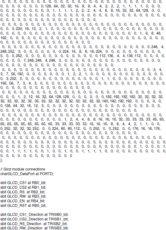
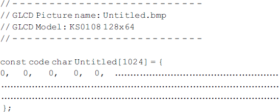
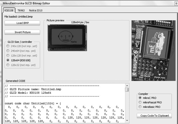
- As shown in Figure 12.4, you should see the image on the virtual GLCD. In addition, the bitmap image code will be shown at the bottom of the tool. The generated code is nothing more than a constant character array that contains information on which pixels of the GLCD should be illuminated to display the image. For a GLCD of 128 × 64 pixels, the size of the array would be 1024 bytes. Part of the generated code is shown below for illustration purposes:
- Click ‘Copy Code to Clipboard’ to save the code in the clipboard for future use.
- We will see later in the project how to use the generated code to display the image on the GLCD.
Figure 12.1 Select the GLCD screen size as 128 × 64 pixels
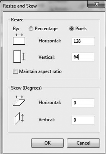
Figure 12.2 The GLCD screen
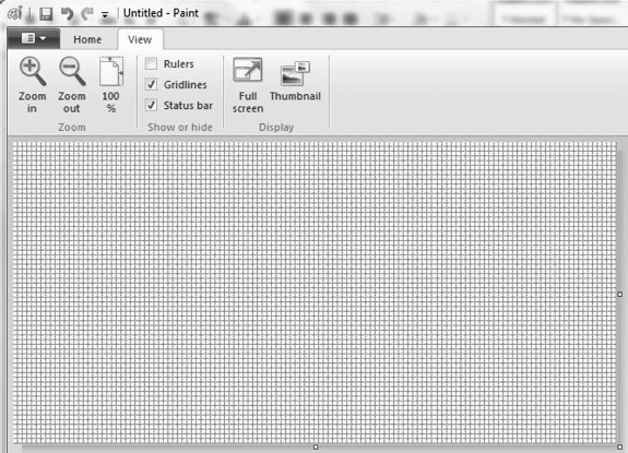
Figure 12.3 Created bitmap image
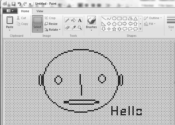
Figure 12.4 Using the GLCD Bitmap Editor
12.1.2 Block Diagram
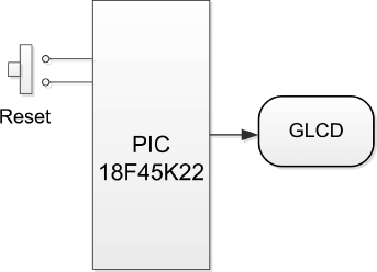
The block diagram of the project is shown in Figure 12.5.
Figure 12.5 Block diagram of the project
12.1.3 Circuit Diagram
The circuit diagram of the project is shown in Figure 12.6. The project is based on the PIC18F45K22 microcontroller, operating with an 8 MHz crystal (although most other types of PIC microcontrollers can also be used).
Figure 12.6 Circuit diagram of the project
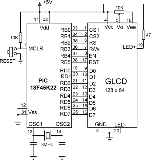
The connections between the GLCD and the microcontroller are as follows:
| GLCD Pin | Microcontroller Pin |
| CS1 | RB0 |
| CS2 | RB1 |
| RS | RB2 |
| R/W | RB3 |
| EN | RB4 |
| RST | RB5 |
| D0 | RD0 |
| D1 | RD1 |
| D2 | RD2 |
| D3 | RD3 |
| D4 | RD4 |
| D5 | RD5 |
| D6 | RD6 |
| D7 | RD7 |
The contrast of the LCD is controlled by connecting a 10 KB potentiometer to pin Vo and Vee of the GLCD. The microcontroller is Reset using an external push-button.
If you are using the EasyPIC 7 development board, you should set the BCK jumper of SW4 to the +5 V position to enable the GLCD backlight. The GLCD contrast can be adjusted by the potentiometer located next to the display.
12.1.4 Project PDL
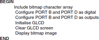
The PDL of this project is very simple and is given in Figure 12.7.
Figure 12.7 PDL of the project
12.1.5 Project Program
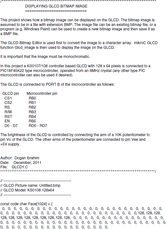
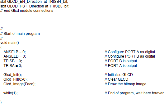
The program is named GLCD1.C and the program listing of the project is shown in Figure 12.8. At the beginning of the program, the bitmap array is declared using the code generated by the Bitmap Editor. Then, the connection between the microcontroller and the GLCD are defined using sbit statements. The GLCD is connected to ports B and D of the microcontroller and thus both of these ports are configured as digital I/O ports using ANSEL statements (different PIC microcontrollers may require different settings). The GLCD library is then initialised using the Glcd_Init function. This function must be called before calling to any other GLCD function. The GLCD screen is then cleared using the Glcd_Fill(0×0), which turns OFF all pixels of the GLCD. The created bitmap is then displayed on the GLCD by calling to function Glcd_Image and entering the name of the bitmap array as an argument.
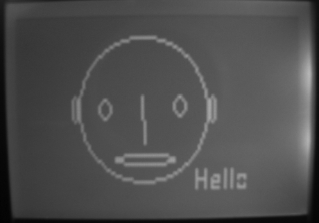
Figure 12.9 shows the created image displayed on the GLCD.
Figure 12.9 Created image displayed on the GLCD
