12.3 PROJECT 12.3 – GLCD Dice
12.3.1 Project Description
In this project we design a GLCD based dice. The shapes of the numbers on two dices are imitated on a GLCD. The user presses a STRT button to ‘throw’ two dices. The dice numbers are then displayed for 5 seconds on the GLCD as real dice faces. After this time, the screen goes blank and the user is ready to ‘throw’ two new dices.
12.3.2 Block Diagram
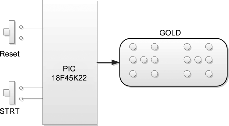
The block diagram of the project is shown in Figure 12.14.
Figure 12.14 Block diagram of the project
12.3.3 Circuit Diagram
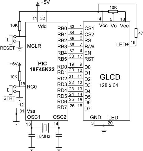
The circuit diagram of the project is shown in Figure 12.15. The GLCD is connected to PORT B and PORT D of the microcontroller. The STRT button is normally at logic 1 and is connected to port pin RC0 of the microcontroller. When the button is pressed, RC0 goes to logic 0.
Figure 12.15 Circuit diagram of the project
12.3.4 Project PDL
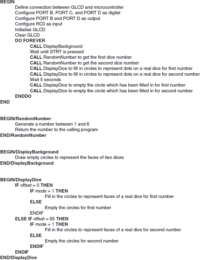
The PDL of this project is given in Figure 12.16.
Figure 12.16 PDL of the project
12.3.5 Project Program
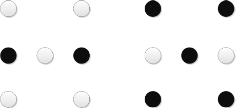
The screen layout of the two dice shapes are designed using the Windows Paint program. Circles are used to represent the dots on a real dice. A dice number is shown by filling these circles to correspond to the dots on the faces of a real dice. Figure 12.17 shows the co-ordinates of the circles for the two dices. As an example, Figure 12.18 shows the dice numbers 2 and 5 being displayed on the GLCD.
Figure 12.17 Co-ordinates of the dice circles
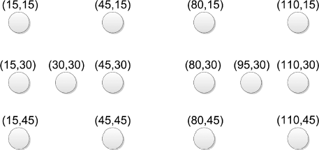
Figure 12.18 Dice numbers 2 and 5 displayed
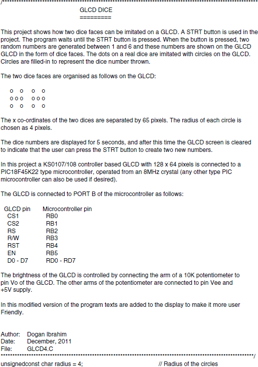
The two dice x co-ordinates are separated from each other by 65 pixels. The radius of the dice circles are selected as 4 pixels.
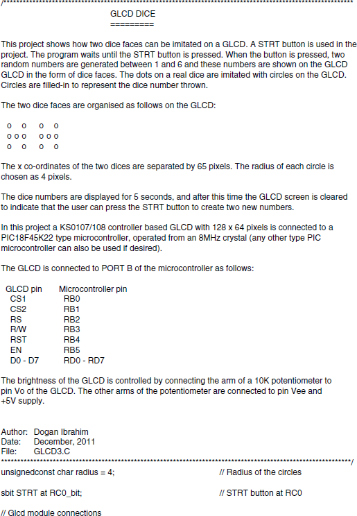
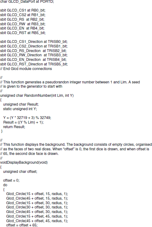
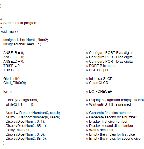
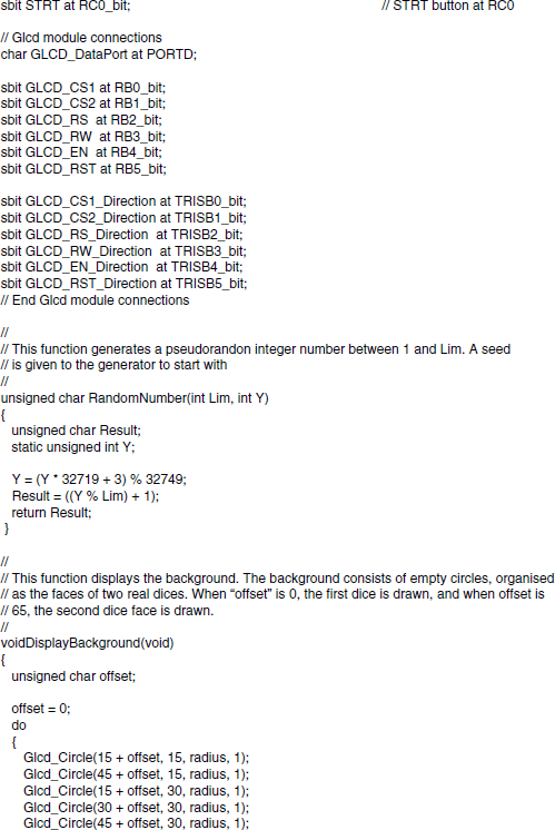
The program is named GLCD3.C and Figure 12.19 shows the program listing of the project. At the beginning of the program, the radius of the circles is defined as 4 pixels and the STRT button is defined as connected to pin RC0 of the microcontroller. Then, the connection between the microcontroller and the GLCD are defined using sbit statements. The GLCD is connected to ports B and D of the microcontroller and thus both of these ports are configured as digital I/O ports using ANSEL statements. The GLCD library is then initialised using the Glcd_Init function. This function must be called before calling to any other GLCD function. The GLCD screen is then cleared using the Glcd_Fill(0×0), which turns OFF all pixels of the GLCD.
Function DisplayBackground is then called. This function displays 5 empty circles to imitate the faces of a real dice. Two dice faces are drawn, separated from each other by 65 pixels. The co-ordinates of the circles are as in Figure 12.17. When variable offset = 0, the first dice face is drawn, and when offset = 65, the second dice face is drawn.
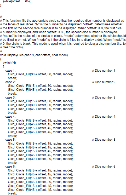
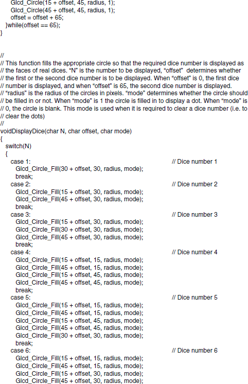
The program then enters an endless loop, formed using a for statement. Inside this loop, the background is displayed and two random dice numbers (Num1 and Num2) are generated between 1 and 6 using function RandomNumber. Function DisplayDice is then called to fill in the appropriate circles, so that the required number is displayed as the dots on the faces of real dices. Here, N is the number to be displayed, and offset determines whether the first or the second dice number is to be displayed. When offset is 0, the first dice number is displayed, and when offset is 65, the second dice number is displayed. radius is the radius of the circles in pixels. mode determines whether a circle should be filled in or not. When mode is 1, the circle is filled in to display a dot. When mode is 0, the circle is drawn blank. This mode is used when it is required to clear a dice number (i.e. to clear the circles). Function DisplayDice uses a switch statement to fill in or empty the circles based on the dice numbers.
The program then waits for 5 seconds and then clears the circles by setting mode to 0 for the circles, which are filled in. At this point, the program is ready, and waits as above for the STRT button to be pressed again so that it generates new dice numbers.
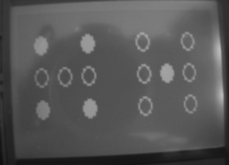
Figure 12.20 shows a typical display of the GLCD.
Figure 12.20 A typical display
12.3.6 Modifying the Program
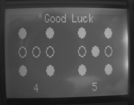
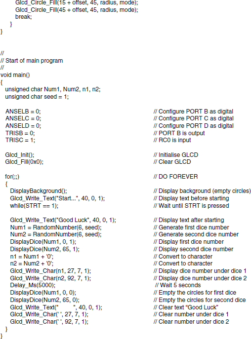
The program given in Figure 12.19 can be made more user friendly by adding text to the display. For example, the text ‘Start . . . ’ can be added to the display before the user presses the STRT button. Also, the text ‘Good Luck’ can be added after the dice figures are displayed. The actual dice numbers can also be displayed at the bottom of each dice figure to make the display more user friendly.
Figure 12.21 shows the modified program (GLCD4.C). Here, the text ‘Start . . . ’ is displayed at the top of the display in Page 0, starting from x co-ordinate 40. The text ‘Good Luck’ is displayed at the same co-ordinates after the two dice numbers are generated. In addition, the two dice numbers Num1 and Num2 are converted into characters n1 and n2, respectively. These characters are then displayed at the bottom of the dice figures. After displaying the texts and the dice figures, the program waits for 5 seconds. After this delay, the filled-in dice circles are changed into empty circles. In addition, the dice number texts are deleted and the text ‘Good Luck’ is changed to ‘Start . . . ’ to tell the user that the STRT button can be pressed again to generate two new dice numbers.
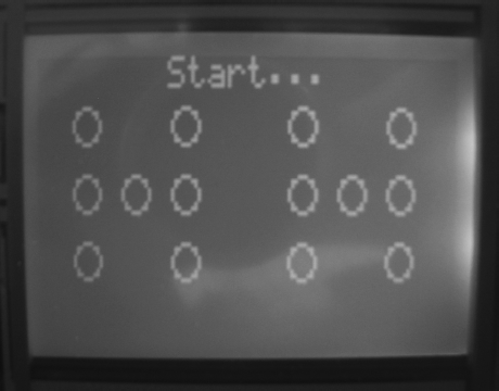
Figure 12.22 shows the GLCD screen before the STRT button is pressed. Figure 12.23 shows the screen after the STRT button is pressed, when two new dice numbers are generated with the modified program.
Figure 12.22 Before pressing the STRT button
Note: The modified program generates a hex code over 2 KB, and thus the Demo version of the mikroC Pro for PIC compiler cannot be used to compile this program.
Figure 12.23 After pressing the STRT button
