9.8 PROJECT 9.8 – Changing the Brightness of LEDs
9.8.1 Project Description
In some applications we may want to change the brightness of an LED. Perhaps the easiest way to do this is to vary the current through the LED by using a potentiometer. By keeping the supply voltage the same, we can connect a potentiometer in series with the LED and by varying the potentiometer we effectively change the current through the LED, which in turn changes its brightness. But in microcontroller applications, we wish to write a program and then change the LED brightness by running the program. Before we can do this, it is worthwhile looking at the theory briefly on how we can change the power delivered to an LED.
One of the common techniques used to change the power delivered to an LED is to use a Pulse-Width-Modulated (PWM) signal. This is basically a positive square wave signal where the ON to OFF period can be changed by software. Let us initially consider applying a square wave signal to the LED with equal ON and OFF periods. If the duration of these signals are long (e.g. 1 s), then we will see the LED flashing ON and OFF. If we now decrease the duration to say around 100 ms, we will see rapid flashing. If we continue to decrease the duration to around 20 ms, the LED will seem to have stopped flashing and we will see reduced brightness. This is because the LED brightness is now determined by the average current produced by the square wave signal. Now, if we change the ON to OFF ratio of the signal, we will see the brightness of the LED changing. This is the principle of controlling the power delivered to the LED using the PWM signal.
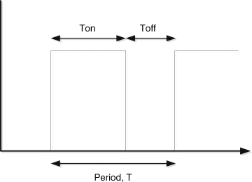
Figure 9.43 shows a typical PWM signal. The ratio of the ON period (also called MARK) to the OFF period (also called SPACE) is known as the Duty-Cycle of the PWM signal. The duty-cycle is quoted as a percentage and is calculated as:
Figure 9.43 PWM signal
(9.2) ![]()
where D is the duty-cycle, T is the period and Ton is the ON time.
When the period is around 20 ms, the human eye will not see the flashes and a continuous brightness will be seen. In this section we will assume a 20 ms (20 000 μs) period. The required ON and OFF times for a given duty-cycle can be calculated as follows:
(9.3) ![]()
or
and
(9.5) ![]()
or
where Ton and Toff are in μs. Equations (9.4) and (9.6) can be used to calculate the required ON and OFF times. For example, for a 75% duty-cycle, the required ON and OFF times are
(9.7) 
As the duty-cycle is varied, the power delivered to the LED and hence the brightness of the LED changes. We can divide the period into equal steps for simplicity and the size of a step is known as the resolution of the PWM signal. Here, the period is 20 000 μs and it is reasonable to divide this into 20 steps, each step being 1000 μs. That is the resolution of our signal will be 1000 μs. This corresponds to 20 steps. That is, we should be able to change the steps and see the changes in the brightness of our LED. Since we have 20 steps, each step corresponds to a change of 5%.
There are several techniques that we can use to generate a PWM signal using a microcontroller. Some of the commonly used techniques are
- using delays in a program;
- using timer interrupts;
- using the built-in PWM module of the microcontroller.
Each technique will be described as a project in the following sections.
9.8.1.1 Using Delays to Generate a PWM Signal
Perhaps the easiest technique to generate a PWM signal is by using delays in a program. Here, we can set up an endless loop and inside this loop we can send a logic HIGH from a microcontroller port, then wait for Ton microseconds. Then, we can send a logic LOW signal from the same port and wait for Toff microseconds. This process can be repeated continuously to generate a continuous PWM signal. The disadvantage of this technique is that the microcontroller is dedicated to generating a PWM signal and it cannot do any other useful work. In addition, the timing of the signal is not accurate.
In this project, the brightness of an LED is controlled by increasing the ON time every second, in steps of 1 ms, from 1 to 20 ms.
9.8.2 Block Diagram
The block diagram of the project is as shown in Figure 9.3.
9.8.3 Circuit Diagram
The circuit diagram of the project is as shown in Figure 9.44, where only a single LED is connected to port pin RC0 of the microcontroller.
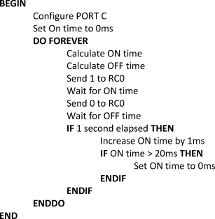
Figure 9.44 PDL of the project
9.8.4 Project PDL
The PDL of this project is given in Figure 9.44.
9.8.5 Project Program
The program is named LED12.C and the program listing of the project is shown in Figure 9.45. The time units used in the program are milliseconds rather than microseconds, as the Delay_us function only accepts constant numbers, not variables. In this program, Vdelay_Ms function is used to create the require delays in milliseconds.
Figure 9.45 Program listing of the project
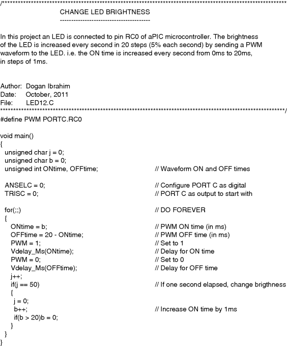
At the beginning of the program, the ON time variable ONtime is initialised to 0. Then, an endless loop is formed using the for statement. Inside this loop, the ON and the OFF times are calculated in milliseconds. Logic 1 is sent to port pin RC0 and the program waits for the duration of the ON time. Then, logic 0 is sent and the program waits for the duration of the OFF time. The ON time is incremented by 1 ms approximately every second. After 50 iterations, the elapsed time is assumed to be 1 second (20 ms × 50 = 1000 ms, i.e. 1 s). When the ON time reaches 20, it is reset back to 0. When the program is run, the brightness of the LED should increase every second. After about 20 seconds, the LED will be OFF and the above process will be repeated.
9.8.6 Using Timer Interrupts to Generate a PWM Signal
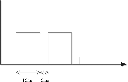
The advantage of using timer interrupts to generate a PWM signal is that the signal is generated in the background and the processor is free to do other tasks. Here, we will set a high-priority timer interrupt using the TMR0 module. The processor will jump to the interrupt service routine (ISR) every 1000 μs. The PWM ON or OFF times will be stored in variables and will be decremented inside the ISR every time an interrupt occurs. When one of the variables reach zero, the output will be toggled. That is, 0 will change to 1, and 1 will change to 0, and this variable will be re-loaded to its initial value. In this project, the PWM ON and OFF times will be set to 15 000 and 5000 μs, respectively.
9.8.6.1 Block Diagram
The block diagram of the project is as shown in Figure 9.3.
9.8.6.2 Circuit Diagram
The circuit diagram of the project is as shown in Figure 9.4, where only a single LED is connected to port pin RC0 of the microcontroller.
9.8.6.3 Project PDL
The PDL of this project is given in Figure 9.46.
Figure 9.46 PDL of the project

9.8.6.4 Project Program
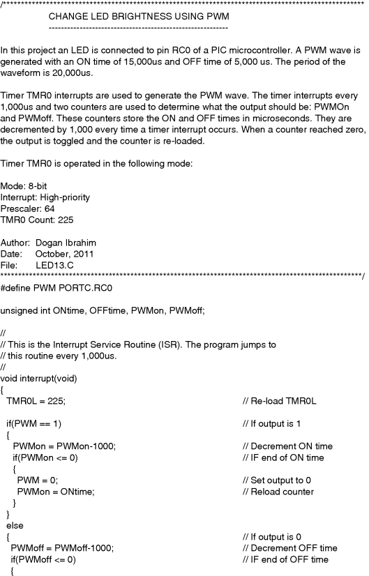
The program is named LED13.C and the program listing of the project is given in Figure 9.47. At the beginning of the program, the period of the PWM wave is defined as 20 000 μs, and PORT C is configured as a digital output port.
The interrupt priority feature is enabled by setting IPEN = 1 and the timer TMR0 interrupts are set to high-priority by setting TMR0IP = 1. The TMR0 interrupt flag is cleared by setting TMR0IF = 0, the timer is set to operate in 8-bit mode and with a prescaler value of 64. As described in Chapter 2, the required timer value to generate interrupts every 1000 μs can be calculated from:
(9.8) ![]()
or
(9.9) ![]()
giving TMR0L = 224.75, the nearest integer is selected, that is TMR0L = 225.
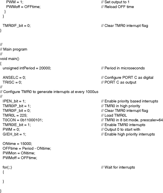
TMR0 interrupts are enabled by setting TMR0IE = 1. Finally, global interrupts are enabled by setting GIEH = 1. The timer is now ready to generate interrupts every 1000 μs. In the main program, the PWM On and OFF times are set to 15 000 and 5000 μs, respectively. The main program then enters an endless loop and waits for timer interrupts to occur.
When an interrupt occurs, the program jumps to the ISR declared as function interrupt. Here, the first task is to re-load the timer register TMR0L. If the output is 1, the ON time is decremented by 1000 μs. When the ON time reaches 0, the output is changed to 0 and the counter is reloaded. If, on the other hand, the output is 0, the OFF time is decremented by 1000 μs. When the OFF time reaches 0, the output is changed to 1 and the counter is reloaded. Just before exiting the ISR, further timer interrupts are re-enabled by clearing the timer interrupt flag TMR0IF.
The PWM output waveform generated by the program in Figure 9.47 is shown in Figure 9.48.
Figure 9.48 Generated PWM waveform
9.8.7 Changing the Brightness Continuously with PWM
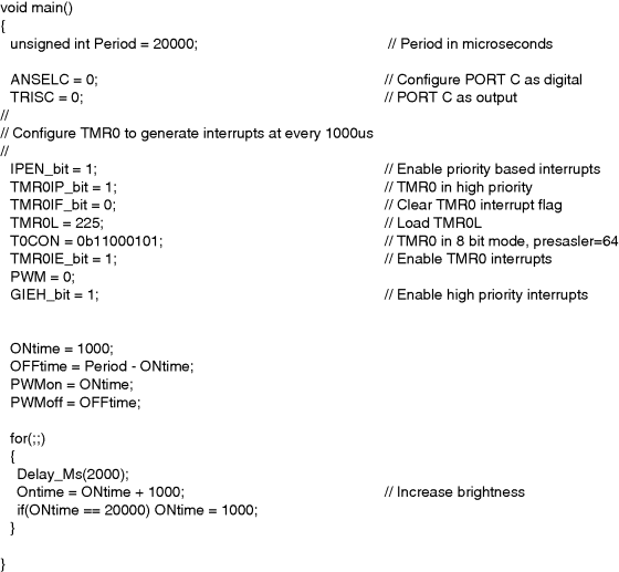
The program given in Figure 9.47 can be modified such that the brightness of the LED can be increased continuously, for example every second. When the LED is fully bright, it can be turned OFF and the above process can be repeated. The new program listing (LED14.C) is shown in Figure 9.49. Here, the main program has been changed by adding 2 seconds of delay and then increasing the brightness every second. In Figure 9.49, only the main program is shown, as the ISR is as before.
Figure 9.49 Modified program to change the brightness
9.8.8 Suggestion for Further Developments
In some applications we may want to control the brightness of multiple LEDs. If all LEDs are to have the same brightness, then we could simply make the following changes to the program:

If, on the other hand, we want to control the brightness of each LED independently, then we could extend the ISR by creating independent counters for each LED and then sending a 1 or 0 to each LED whenever its counter becomes 0.
9.8.9 Using the Built-in Microcontroller PWM Module
The PIC18 microcontroller family has built-in PWM modules (see Chapter 2) that can be used to generate PWM waveforms. PWM module makes use of ports CCP1, CCP2, CCP3, and so on, of the microcontroller. But unfortunately this module cannot be used to generate PWM signals with large periods such as 20 ms. In this project we shall be using the CCP1 pin and connect an LED to this pin via a current limiting resistor and we will generate a PWM signal with a period of 2000 μs, ON time (duty cycle) of 500 μs, and OFF time of 1500 μs. The advantage of using the PWM module is that, like the interrupts, the waveform is generated in the background and the processor is free to do other tasks while the PWM signal is being generated.
9.8.9.1 Block Diagram
The block diagram of the project is as shown in Figure 9.3.
9.8.9.2 Circuit Diagram
The circuit diagram of the project is as shown in Figure 9.4, except that the LED is connected to port pin CCP1 (pin RC2 in PIC18F45K22 microcontroller) via a current limiting resistor.
9.8.9.3 Project PDL
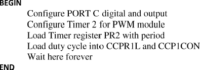
The PDL of this project is given in Figure 9.50.
Figure 9.50 PDL of the project
9.8.9.4 Project Program
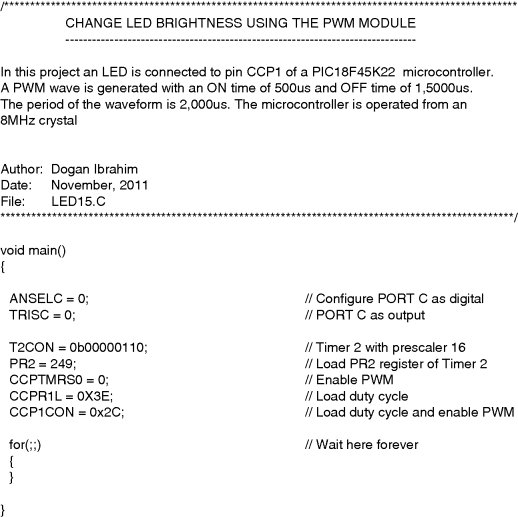
The program is named LED15.C and the program listing of the project is shown in Figure 9.51.
Figure 9.51 Program listing using the PWM module
As described in Chapter 2, the value to be loaded into Timer 2 register can be calculated as
(9.10) ![]()
where
Substituting the values into the equation, and assuming a prescaler of 16, an oscillator frequency of 8 MHz (Tosc = 0.125 μs), the PWM period of 2000 μs, and duty cycle (ON time) of 500 μs, we get
(9.11) ![]()
which gives PR2 = 249
The 10-bit value to be loaded into PWM registers are given by (see Chapter 2)
(9.12) ![]()
where the upper 8 bits will be loaded into register CCPR1L and the two LSB bits will be loaded into bits 4 and 5 of CCP1CON.or
(9.13) ![]()
which gives 250. This number in 10-bit binary is ‘00111110 10’. Therefore, the value to be loaded into bits 4 and 5 of CCP1CON are the two LSB bits. that is ‘10’. Bits 2 and 3 of CCP1CON must be set to HIGH for PWM operation, and bits 6 and 7 are not used. Therefore, CCP1CON must be set to (‘X’ is don't care):
![]()
The number to be loaded into CCPR1L is the upper 8 bits (of 250), that is ‘00111110’, that is hexadecimal 0 × 3E.
At the beginning of the program, PORT C is configured as digital output port. Then, Timer 2 is configured and timer register PR2 is loaded to give the required period. PWM registers CCPR1L and CCP1CON are loaded with the duty cycle (ON time) and the PWM module is enabled. The main program then waits forever, where the PWM works in the background to generate the required waveform.
9.8.10 Changing the LED Brightness using the PWM Module
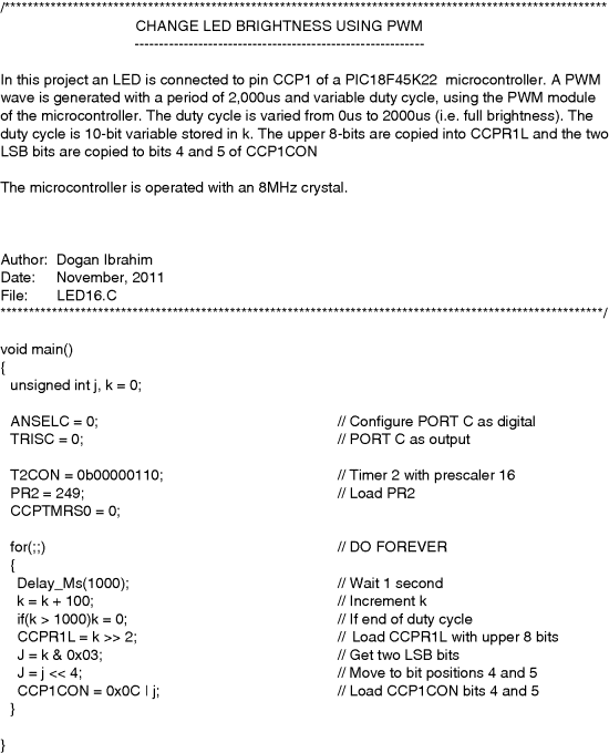
The program given in Figure 9.51 generates a single PWM waveform to reduce the brightness of an LED. In this section we will modify the program, such that the LED brightness changes continuously, for example every second.
In reference to the duty cycle formula, we can write the duty cycle as:
or
giving
Now, by loading different values into the register pair CCPR1L and CCP1CON, we can obtain different duty cycles and hence different LED brightness. Remembering that the period of our PWM wave is 2000 μs, we can load values from 0 to 1000 into the register pair to correspond with no brightness to full brightness. Let us assume that we wish to change the brightness in 10 steps. Then, we could increase the value loaded into these registers by 100 every second, so that the duty cycle changes by 200 μs. What we will see is that the brightness of the LED will change from 0 to full brightness in 10 seconds, in steps of 10 levels.
Figure 9.52 shows the modified program (LED16.C). Here, variable k is used to increment the 10-bit value of the register pair by 100, that is the duty cycle is incremented by 200 μs. Variable k is shifted right by 2 bits and the upper 8 bits of the 10-bit duty cycle is loaded into register CCPR1L. Then, the two LSB bits of the duty cycle are extracted and ORed with register CCP1CON to enable the PWM and also to provide the 2 LSB bits of the duty cycle.
Figure 9.52 Modified program
