14.2 PROJECT 14.2 – Toggle more than One LED
14.2.1 Project Description
This project is similar to the previous project, but here the user is given the option of toggling more than one LED. Four upper bits of PORT C (RC4 to RC7) are used in the project, and the screen offers the following options:
- Turn OFF all LEDs RC4 to RC7.
- Turn ON all LEDs RC4 to RC7.
- Toggle individual LEDs from RC4 to RC7.
14.2.2 Block Diagram
The block diagram of the project is the same as in Figure 13.3, but four LEDs are connected to upper four pins of PORT C instead of just one LED.
The operation of the project is as follows: After power-up and calibration, the user can touch the ALL ON box to turn ON all the four LEDs. Similarly, touching the All OFF box will turn OFF all the four LEDs. Touching the boxes for individual LEDs will toggle the corresponding LEDs.
14.2.3 Circuit Diagram
The circuit diagram of the project is as shown in Figure 13.5. A standard 128 × 64 pixel GLCD is used in this project. Switching transistors are used as the touch screen controller. A PIC18F45K22 type microcontroller is used with an 8 MHz crystal.
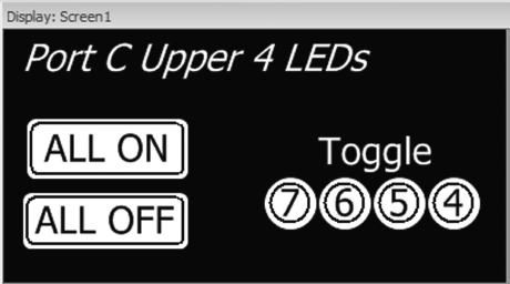
The project creation and configuration are as in the previous project. The project is named TOGGLEALL. The components are placed on the screen, as shown in Figure 14.9. ALL ON, ALL OFF boxes are shown as ‘Rounded Buttons’. The LEDs are shown as ‘Circles’.
Figure 14.9 Adding Components onto the Screen
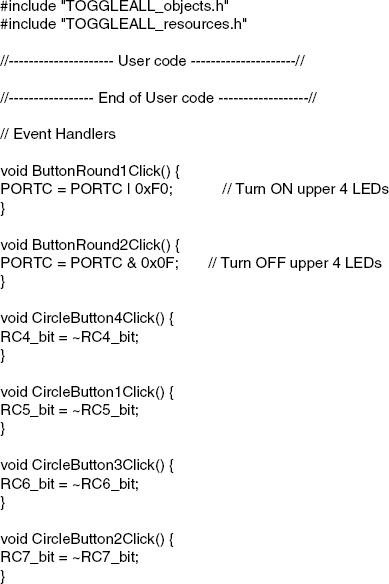
The contents of the user created events file are shown in Figure 14.10. Notice how the events are created as functions.
Figure 14.10 Contents of the events file
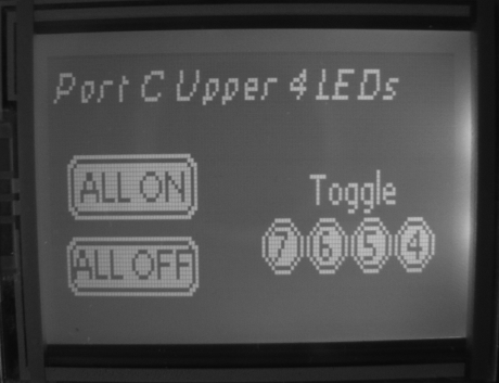
When the program is run, initially the screen is calibrated, and then the various shapes are shown on the display, as in Figure 14.11. Clicking box ALL ON will turn ON all four upper LEDs of PORT C. Similarly, clicking ALL OFF will turn OFF all four upper LEDs of PORT C. Individual bits of the upper four LEDs can be toggled by clicking on the appropriate bit number.
Figure 14.11 Typical display when the program is run