5.1 A Typical LED
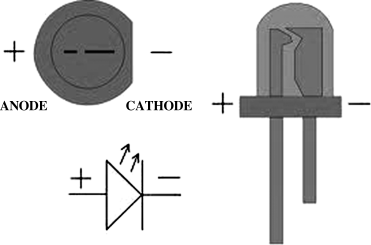
Figure 5.1 shows a typical LED with the electronic circuit symbol similar to that of a semiconductor diode. The device has two legs: the longer leg is the anode and the shorter leg the cathode. The cathode is also identified by a flat side on the body.
Figure 5.1 A typical LED

The intensity of the light emitted by an LED depends on the amount of forward current passed through the device. The maximum allowable forward current is denoted by IFmax. When designing an LED circuit, we have to know the typical voltage drop, VTyp across the device, and the maximum allowable voltage drop, VFmax.
The brightness of the emitted light is measured in millicandela (mcd) and this is usually referenced to the forward current. For example, standard red LEDs are quoted to have brightness of 5 mcd when operated at 10 mA.
The viewing angle of a standard LED is about 60°, although some LEDs have viewing angles as narrow as 30°.
The colour of an LED depends on the type of chemical material used in its construction, and not on the colour of the glass enclosing the LED. As we shall see later, the colour of an LED is specified by giving the wavelength of the emitted light.
Most LEDs have typical forward voltage drop of 2 V, while blue and white ones can have as high as 4 V. The typical operating current is around 10 mA, although some small low-current LEDs can operate at around 1 mA. The higher the forward current the brighter the LED becomes, but care should be taken not to exceed the specified maximum allowable forward current.
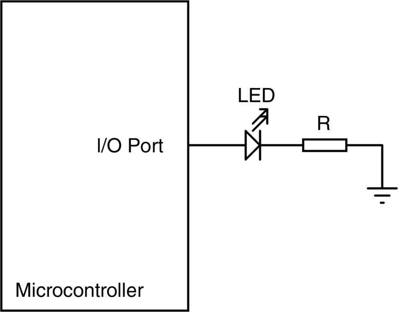
Figure 5.2 shows the connection of an LED to a microcontroller output port. The port output voltage can be assumed to be +5 V when the port is at logic HIGH. Assuming that the LED is to be operated with 10 mA forward current, and that it has a forward voltage drop of 2 V, we can easily calculate the value of the current limiting resistor as
(5.1) ![]()
Figure 5.2 LED to microcontroller interface

The nearest resistor we can choose is 330 Ω. It is interesting to note that the I/O pin of a PIC microcontroller can provide up to 25 mA current and thus LEDs can be driven with higher currents if desired, in order to obtain more brightness.
LEDs can easily be connected in series in circuits. When calculating the required current limiting resistor in such applications, the total voltage drop across all the LEDs should be taken as the overall forward voltage drop. LEDs can also be connected in parallel. When the same types of LEDs are connected in parallel, the value of the current limiting resistor is calculated by doubling the forward current requirements (e.g. 20 mA) and keeping the same forward voltage drop (e.g. 2 V). When different LEDs are connected in parallel, the situation is more complex, as only the LED with the lowest voltage drop will light and the high current through this LED may destroy it. It is best to use separate current limiting resistors in such applications.
