12.6 PROJECT 12.6 – Temperature and Relative Humidity Measurement
12.6.1 Project Description
This project demonstrates how the ambient temperature and relative humidity can be measured and then displayed on the GLCD.
In this project, the SHT11 relative humidity and temperature sensor chip is used. This is a tiny 8-pin chip with dimensions 4.93 × 7.47 mm and thickness 2.6 mm, manufactured by Sensirion (http://www.sensirion.com). A capacitive sensor element is used to measure the relative humidity, while the temperature is measured by a band-gap sensor. A calibrated digital output is given for ease of connection to a microcontroller. The relative humidity is measured with an accuracy of ±4.5%RH and the temperature accuracy is ±0.5°C. Operating voltage ranges from a minimum of +2.4 V to a maximum of +5.5 V.
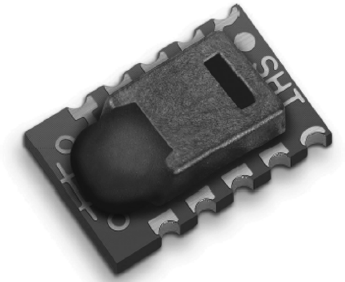
Figure 12.34 shows a picture of the SHT11 sensor. The sensor is available as a small PCB that can be plugged into a development board (e.g. EasyPIC 7) for ease of use.
Figure 12.34 The SHT11 sensor

The pin configuration of the sensor is as follows:
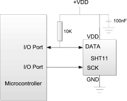
As shown in Figure 12.35, the SHT11 sensor is connected to a microcontroller using only two pins. The data pin should be pulled up to the supply voltage using a 10 KB resistor. It is recommended to use a 100 nF decoupling capacitor between pin 4 and ground.
Figure 12.35 Connection of SHT11 to a microcontroller

