13.1 PROJECT 13.1 – Touch Screen LED ON-OFF
13.1.1 Project Description
This is perhaps the simplest GLCD project utilising touch screen. In this project, an LED is connected to pin RC7 of the microcontroller. Two buttons are placed on the screen, labelled ON and OFF. Touching the ON button will turn the LED ON. Similarly, touching the OFF button will turn the LED OFF.
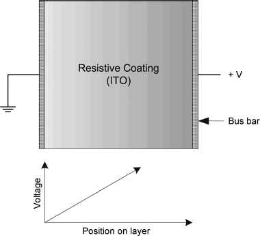
The principle of operation of a touch screen is such that, as shown in Figure 13.1, if one side of a layer is connected to +V and the other side to ground, a potential gradient results on the screen layer, and the voltage at any point on this layer becomes directly proportional to the distance from the +V side.
Figure 13.1 Voltage gradient in a screen layer
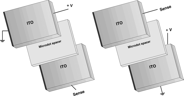
In a 4-wire resistive touch screen, two measurements are made one after the other one to determine the X and Y co-ordinates of the point touched by the user. Figure 13.2a shows how the X co-ordinate can be determined. Here, the right- and left-hand sides of the top layer can be connected to +V and ground, respectively. The bottom layer can then be used to sense and measure the voltage at the point touched by the user. An A/D converter is used to convert this voltage to digital and then determine the X co-ordinate. Similarly, Figure 13.2b shows how the Y co-ordinate can be determined. Here, the upper and lower sides of the bottom layer can be connected to +V and ground, respectively. The top layer can then be used to sense and measure the voltage at the point touched by the user. Again, an A/D is used to convert the voltage to digital and then to determine the Y co-ordinate.
Figure 13.2 Determining the X and Y co-ordinates. (a) Determining the X co-ordinate (b) Determining the Y co-ordinate
13.1.2 Block Diagram
The block diagram of the project is shown in Figure 13.3. The touch screen graphics display will show the images, as shown in Figure 13.4. Rectangles and boxes will be drawn on the screen with text inside them. The screen is 128 pixels horizontal and 64 pixels vertical, with the origin at the top left corner, the X axis to the right and the Y axis downwards. The co-ordinates of the shapes are also shown in Figure 13.4.
Figure 13.3 Block diagram of the project
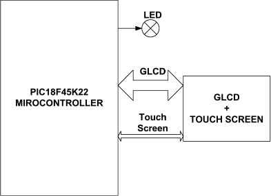
Figure 13.4 Screen layout
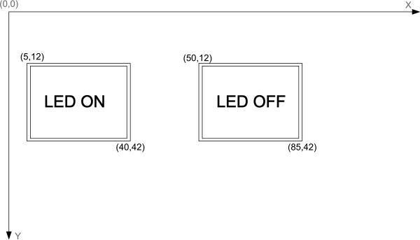
The operation of the project is as follows: After power-up, the LED is OFF. The user can then touch the LED ON box to turn ON the LED. Touching the LED OFF box will turn the LED OFF.
13.1.3 Circuit Diagram
The circuit diagram of the project is shown in Figure 13.5. PORT B and PORT D of the microcontroller are connected to the GLCD. The connections between the microcontroller and the GLCD are as follows:
| GLCD Pin | Microcontroller Pin |
| D0–D7 | RD0-RD7 |
| CS1 | RB0 |
| CS2 | RB1 |
| RS | RB2 |
| R/W | RB3 |
| E | RB4 |
| RST | RB5 |
Figure 13.5 Circuit diagram of the project
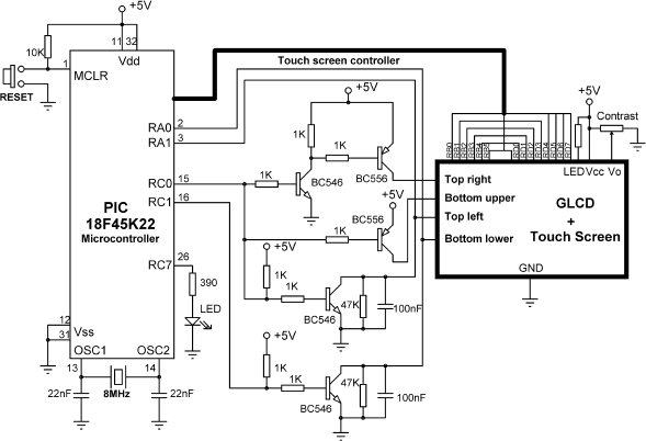
The background light of the GLCD is turned ON permanently by connecting the LDE input to +5 V via a resistor, and the GLCD contrast is adjusted using a 10 KB potentiometer.
In addition, as we shall see later in this section, the touch panel uses pins RA0, RA1, RC0 and RC1 of the microcontroller.
In a microcontroller touch screen interface, a controller circuit is usually required to provide the correct logic levels to the touch screen pins. Normally, logic 0, logic 1 and OFF state are required. The OFF state can be provided using an open-drain microcontroller pin in input mode. Alternatively, touch screen controller chips, such as AD785 or AD7846, can be used to provide the necessary interface voltage levels. In circuit 13.5, switching transistors are used as the touch screen controller. For example, when RC0 is set to logic 1, Top Right pin becomes 1, Top Left pin becomes 0 and Bottom Upper pin becomes OFF.
13.1.3.1 Measuring the X Co-ordinate
In reference to Figure 13.6, and assuming the top layer has contacts Top Right and Top Left and the bottom layer has contacts Bottom Upper and Bottom Lower, the following setup is required to determine the X co-ordinate:
| Top Left: | Ground |
| Top Right: | +5 V |
| Bottom Lower: | To A/D converter (X co-ordinate) |
| Bottom Upper: | OFF |
Figure 13.6 Connection of the touch screen
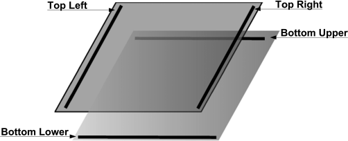
Similarly, to determine the Y co-ordinate, the following setup should be made:
| Top Left: | To A/D converter (Y co-ordinate) |
| Top Right: | OFF |
| Bottom Lower: | Ground |
| Bottom Upper: | +5 V |
In Figure 13.6 for example, the X co-ordinate can be read into analogue port RA0 when:
| RC0 = 1 | (Top Left = 0, Top Right = 1, Bottom Upper = OFF) |
| RC1 = 0 | (Bottom Lower = OFF) |
| Read RA0 | (Read Bottom Lower) |
Similarly, to read the Y co-ordinate:
| RC0 = 0 | (Top Left = OFF, Top Right = OFF, Bottom Upper = 1) |
| RC1 = 1 | (Bottom Lower = Ground) |
| Read RA1 | (Read Top Left) |
If you are using the EasyPIC 7 development board, connect the touch screen flat cable, and then connect the GLCD into its socket. Set switch SW3 jumpers 4 to 7 to ON position to connect the RA0, RA1, RC0 and RC1 pins to the touch-screen controller circuit (see the EasyPIC 7 development board User Guide for further information).
13.1.4 Project PDL
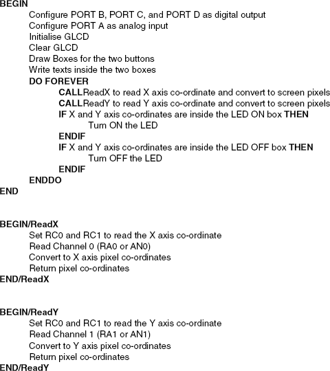
The PDL of this project is very simple and is given in Figure 13.7.
Figure 13.7 PDL of the project
13.1.5 Project Program
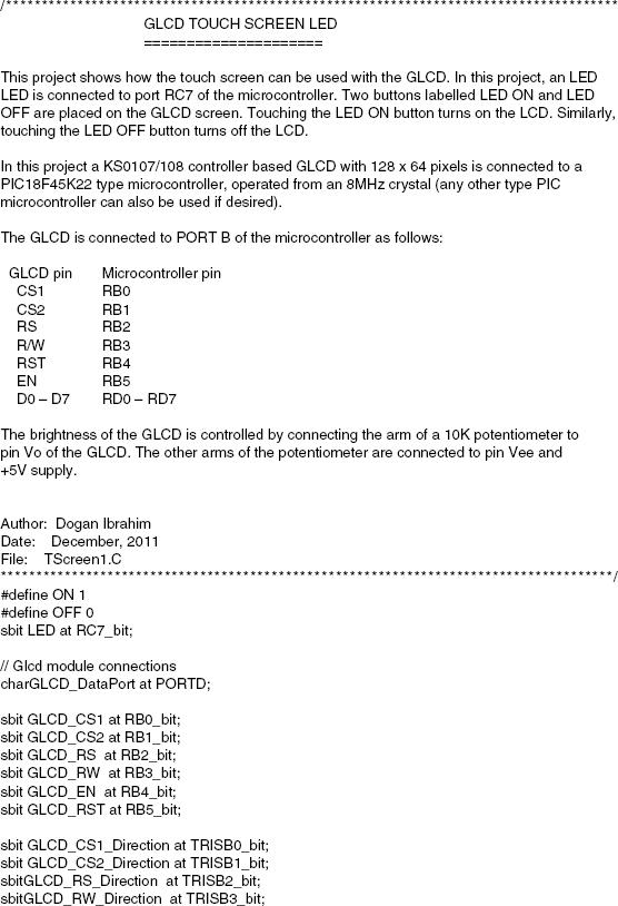
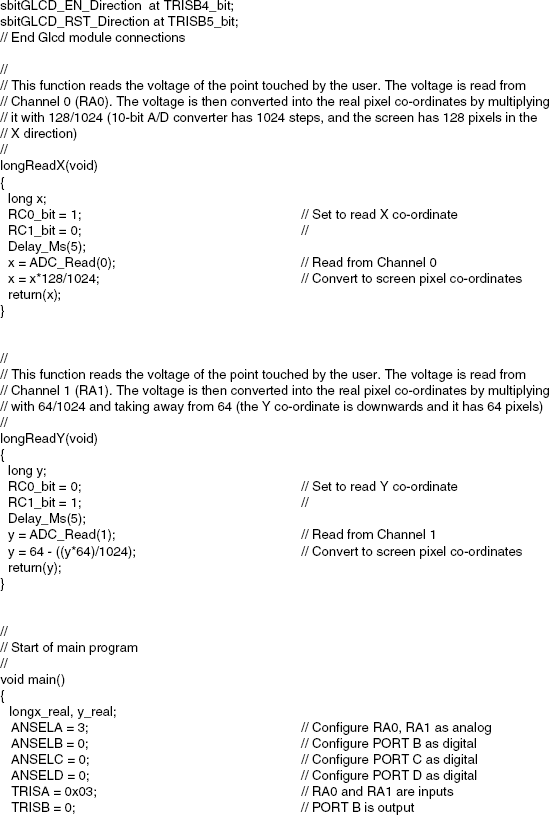
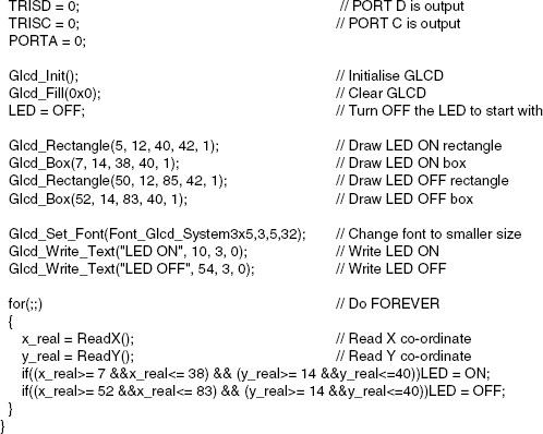
The program is named TScreen1.C and the program listing of the project is shown in Figure 13.8. At the beginning of the project, symbols ON and OFF are defined as 1 and 0, respectively, and LED is assigned to port pin RC7. Then, the connection between the microcontroller and the GLCD are defined using sbit statements. PORT B and PORT D are used to drive the GLCD and both of these ports are configured as digital output. PORT C is also configured as digital output, since the LED is connected to pin RC7 of this port. PORT A is configured as analogue and bits 0 and 1 of this port are configured as inputs, so that RA0 (or AN0) and RA1 (or AN1) become analogue input ports.
The GLCD is then initialised, the screen is cleared, and the LED is turned OFF at the beginning of the program. The program then draws two boxes with rectangle edges and writes the texts LED ON and LED OFF inside these boxes. The rectangles and boxes are drawn using the Glcd_Rectangle and Glcd_Box functions, respectively, at the following co-ordinates:

The text font is changed to 3 × 5 and texts are written inside the boxes using the following GLCD functions:

The main part of the program is executed in an endless loop, formed using a for statement. Inside this loop, the X and Y co-ordinates of the screen are read by calling functions ReadX and ReadY. Function ReadX reads the analogue voltage corresponding to the point touched by the user, and returns the real X co-ordinate of this point as the pixel co-ordinate. Notice that since a 10-bit A/D converter is used, the voltage read is converted to the pixel co-ordinate by multiplying it with 128/1024. Similarly, function ReadY reads the analogue voltage corresponding to the point touched by the user and returns the real Y co-ordinate touched by the user as the pixel co-ordinate. Here also, the voltage read is converted to the pixel co-ordinate by multiplying it with 64/1024 and subtracting from 64, since the Y co-ordinate is downwards. Notice that the Y co-ordinate of the touch screen is not very accurate since the number of pixels in the Y direction is small and the voltage read is multiplied by 64/1024 = 0.0625. Thus, for example, if the converted digital value is 0 or 10, or even 15, the same value will be returned by the function. The program then checks to see whether or not the touched point is inside the shape labelled LED ON, and if so, the LED is turned ON. Similarly, the LED is turned OFF if the point touched by the user is inside the shape labelled LED OFF.
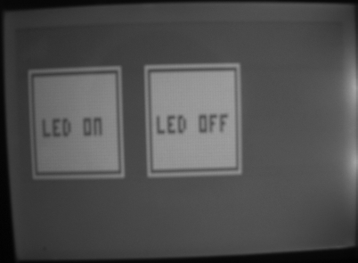
Figure 13.9 shows a typical display on the GLCD.
Figure 13.9 Typical display on the GLCD
