12.7 Operation of the SHT11
The SHT11 is based on serial communication where data is clocked in and out, in synchronisation with the SCK clock. The communication between the SHT11 and a microcontroller consists of the following protocols (see the SHT11 data sheet for more detailed information).
12.7.1 RESET
At the beginning of data transmission, it is recommended to send a RESET to the SHT11, just in case the communication with the device is lost. This signal consists of sending 9 or more SCK signals while the DATA line is HIGH. Then, a Transmission-Start-Sequence must be sent. Figure 12.36 shows the RESET sequence.
Figure 12.36 The SHT11 RESET sequence

The C code to implement the RESET sequence as a function is given below (SDA and SCK are the DATA and SCK lines, respectively). Notice that the manufacturer's data sheet specifies that after the SCK changes state it must remain in its new state for a minimum of 100 ns. Here, a delay of 1 µs is introduced between each SCK state change:

Notice that when the direction of a port pin is set to 1 (i.e. when in input mode), the port pin presents itself as a logic HIGH.
12.7.2 Transmission-Start-Sequence
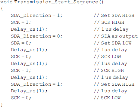
Before a temperature or relative humidity conversion command is sent to the SHT11, the transmission-start-sequence must be sent. This sequence consists of lowering the DATA line while SCK is HIGH, followed by a pulse on SCK and rising DATA again while SCK is still HIGH. Figure 12.37 shows the transmission-start-sequence.
Figure 12.37 The transmission-start-sequence

The C code to implement the transmission-start-sequence is given below:

12.7.3 Conversion Command
After sending the transmission-start-sequence, the device is ready to receive a conversion command. This consists of 3 address bits (only ‘000’ is supported) followed by 5 command bits. The list of valid commands is shown in Table 12.1. For example, the commands for relative humidity and temperature are ‘00000101’ and ‘00000011’, respectively. After issuing a measurement command, the sensor sends an ACK pulse on the falling edge of the 8th SCK pulse. The ACK pulse is identified by the DATA line going LOW. The DATA line remains LOW until the 9th SCK pulse going LOW. The microcontroller then has to wait for the measurement to complete. This can take up to 320 ms. During this time, it is recommended to stop generating clocks on the SCK line and release the DATA line. When the measurement is complete, the sensor pulls the DATA line LOW to indicate that the data is ready. At this point, the microcontroller can restart the clock on the SCK line to read the measured data. Notice that the data is kept in the SHT11 internal memory until it is read out by the microcontroller.
Table 12.1 List of valid commands.
| Command | Code |
| 00011 | Measure temperature |
| 00101 | Measure relative humidity |
| 00111 | Read Status register |
| 00110 | Write Status register |
| 11110 | Soft Reset (reset interface, clear Status register) |
The data readout consists of 2 bytes of data and 1 byte of CRC checksum. The checksum is optional and if not used the microcontroller may terminate the communication by keeping the DATA line HIGH after receiving the last bit of the data (LSB). The data bytes are transferred with MSB first and are right-justified. The measurement can be for 8, 12 or 14 bits wide. Thus, the 5th SCK corresponds to the MSB data for 12-bit operation. For 8-bit measurement, the first byte is not used. The microcontroller must acknowledge each byte by pulling the DATA line LOW, and sending a SCK pulse. The device returns to sleep mode after all the data has been read out.
