12.2 PROJECT 12.2 – Moving Ball Animation
12.2.1 Project Description
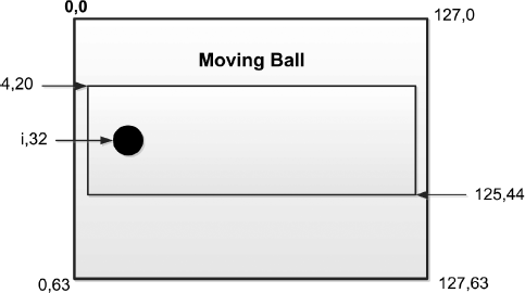
This project shows how the simple animation of a moving ball can be created on the GLCD. A filled circle is drawn to represent the ball. This figure is then moved across the GLCD screen from left-to-right and then right-to-left inside a rectangular shape. The text ‘Moving Ball’ is written on the shape. The format of the display and co-ordinates of the shapes on the screen are shown in Figure 12.10.
Figure 12.10 Ball animation

12.2.2 Block Diagram
The block diagram of the project is as shown in Figure 12.5.
12.2.3 Circuit Diagram
The circuit diagram of the project is as shown in Figure 12.6.
12.2.4 Project PDL
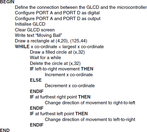
The PDL of this project is given in Figure 12.11.
Figure 12.11 PDL of the project

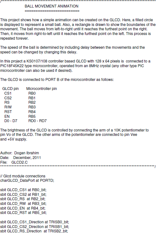
12.2.5 Project Program
The program is named GLCD2.C and the program listing of the project is given in Figure 12.12. At the beginning of the program, the connection between the microcontroller and the GLCD are defined using sbit statements. The GLCD is connected to ports B and D of the microcontroller and thus both of these ports are configured as digital I/O ports using ANSEL statements. The GLCD library is then initialised using the Glcd_Init function. This function must be called before calling to any other GLCD function. The GLCD screen is then cleared using the Glcd_Fill(0×0), which turns OFF all pixels of the GLCD.
The text ‘Moving Ball’ is displayed in Page 1, starting from x co-ordinate 30. Then a rectangle is drawn where the ball moves. The top left and bottom right co-ordinates of this rectangle are (4,20) and (125,44), respectively. Variable flag is used to determine the direction of movement. The ball moves from left-to-right when flag = 1, and from right-to-left when flag = 0. GLCD function Glcd_Circle_Fill is used to represent the ball. This function draws a filled circle with the specified radius, at the given x,y co-ordinates of the screen. The y co-ordinate of the ball is fixed at 32, while the x co-ordinate varies between 10 and 120 as the ball moves from left-to-right. The movement of the ball is animated first by displaying the ball, and after a short delay by erasing the ball and drawing a new one slightly to the right (or left) of the previous position. This way the ball shape seems as if it is moving. By varying the delay, we can modify the speed of movement. The x co-ordinate of the ball is incremented or decremented by 10 pixels as the ball moves from left-to-right or right-to-left, respectively. When the ball reaches the furthest point on the right-hand side, its direction is changed by clearing flag to 0. Similarly, when the ball reaches the furthest point on the left-hand side, its direction is changed by setting flag to 1.
The reader can experiment the effects on animation of changing the delay, size of the shape, and the step size.
Figure 12.13 shows the created image displayed on the GLCD screen.
Figure 12.13 Created image displayed on the GLCD


