5.8 7-Segment LEDs
7-segment displays were the earliest LED type electronic displays used to display numbers. These devices are commonly used in digital clocks and watches, electronic meters, electronic counting devices, and other equipment for displaying numeric only data.
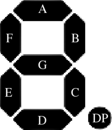
A 7-segment LED consists of 7 light emitting elements arranged in a rectangular enclosure, and by turning the appropriate segments ON and OFF we can obtain the numbers 0 to 9. Figure 5.9 shows a typical 1-digit 7-segment display. Optionally, a decimal point is available to display fractional non-integer numbers. The segments of the displays are referred to by letters ‘a’ to ‘g’.
Figure 5.9 Typical 7-segment display
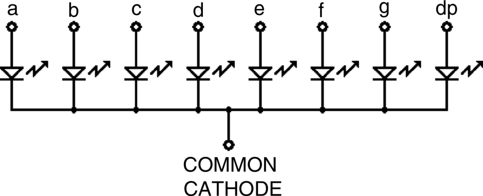
7-segment displays are available in two configurations: common anode and common cathode. As shown in Figure 5.10, in a common anode connection, the anode pins of all the segments are connected together and this pin is usually connected to the power supply. Individual segments are turned ON by grounding the required segment pin. Similarly, Figure 5.11 shows a common cathode display. Here, the cathodes of all the segments are connected together and this pin is usually connected to ground. Individual segments are turned ON by applying voltage to the required segment pin.
Figure 5.10 Common anode 7-segment LED
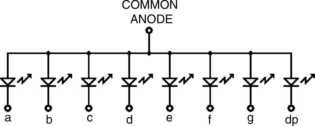
Figure 5.11 Common cathode 7-segment LED
5.8.1 Displaying Numbers
Figure 5.12 shows the connection between a microcontroller and a 7-segment display. As with standard LEDs, it is required to use current limiting resistors in each segment of the display to limit the current. Usually, resistor packages are used for ease of construction, lower cost and to save space. These packages consist of 8 or 10 same value resistors in a SIL (Single-In-Line) type package with a common pin that can be grounded or connected to +V, depending on whether a common cathode or common anode display is used, respectively.
Figure 5.12 Connecting a 7-segment display to a microcontroller
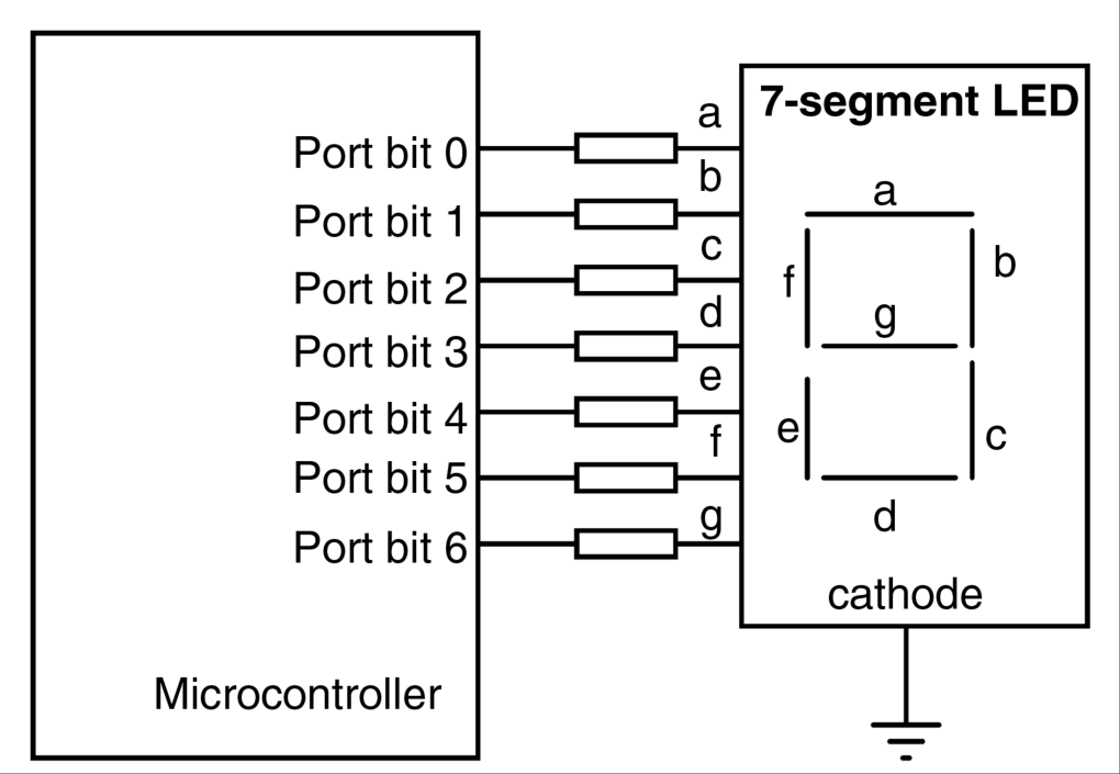
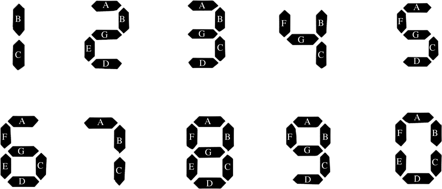
Figure 5.13 shows how the numbers 0 to 9 can be displayed by a 7-segment display. Notice that some symbols and lowercase letters (e.g. ‘b’, ‘c’, ‘d’, ‘o’, etc.) can also be displayed. In the early days of LEDs, 7-segment displays were used to display hexadecimal numbers from ‘0’ to ‘9’ and ‘a’ to ‘f’.
Figure 5.13 Displaying numbers 0 to 9
The easiest way to display a number on the 7-segment LED is first to create a table showing the numbers and corresponding segments that should be turned ON or OFF to display the required number. Then, the bit pattern (or hexadecimal equivalent) required to display a number can be determined and the required number can be displayed by sending this bit pattern to the device. Table 5.3 shows the 7-segment LED encoding where numbers, the corresponding segment status, and the hexadecimal numbers required to be sent to the port where the display is connected to in order to display a specific number, are given. In constructing this table, it is assumed that the 8th bit of the microcontroller is 0, as it is not used by the display. For example, to display number 5, we have to send the hexadecimal number 0 × 6D to the port that the display is connected to.
Table 5.3 7-segment LED encoding.
| Number | x g f e d c b a | Hexadecimal |
| 0 | 0 0 1 1 1 1 1 1 | 3F |
| 1 | 0 0 0 0 0 1 1 0 | 06 |
| 2 | 0 1 0 1 1 0 1 1 | 5B |
| 3 | 0 1 0 0 1 1 1 1 | 4F |
| 4 | 0 1 1 0 0 1 1 0 | 66 |
| 5 | 0 1 1 0 1 1 0 1 | 6D |
| 6 | 0 1 1 1 1 1 0 1 | 7D |
| 7 | 0 0 0 0 0 1 1 1 | 07 |
| 8 | 0 1 1 1 1 1 1 1 | 7F |
| 9 | 0 1 1 0 1 1 1 1 | 6F |
5.8.2 Multi-digit 7-Segment Displays
A 1-digit 7-segment display can only show numbers 0 to 9. In many applications, segments are joined together to create larger displays. A 2-digit display can show numbers between 0 and 99, a 3-digit between 0 and 999, a 4-digit between 0 and 9999, and so on.
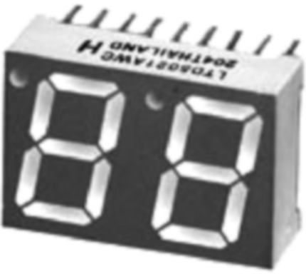
Figure 5.14 shows a typical 2-digit 7-segment display. The digits are normally multiplexed to save I/O pins. For example, without multiplexing, a 2-digit display will require 14 pins, a 3-digit display will require 21 pins, and so on. With multiplexing, a 2-digit display will require only 9 pins, a 3-digit display will require 10 pins, and so on. Another advantage of multiplexing 7-segment LEDs is to reduce the power consumption considerably.
Figure 5.14 A 2-digit 7-segment display
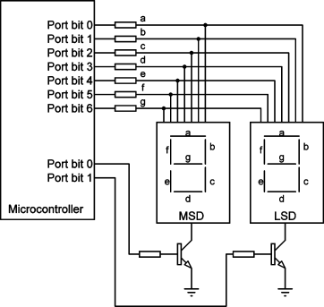
In multiplexed applications, all the digit segments are driven in parallel at the same time, but only the common pin (e.g. anode or cathode) of the required digit is enabled. The digits are enabled and disabled so fast that it gives the impression to the eye that both displays are ON at the same time. For example, suppose that we wish to display the number ‘25’ on a 2-digit common cathode display. The steps are given below:
The common pins of each digit are usually controlled using transistors switches. Figure 5.15 shows how a 2-digit display can be connected to a microcontroller using npn transistors to control the segment lines. Notice that setting the base of a transistor to logic HIGH will turn the transistor ON and hence will enable the common cathode pin connected to it.
Figure 5.15 Connecting a 2-digit display to a microcontroller
