6.1 HD44780 Controller
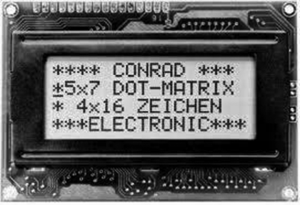
HD44780 is perhaps the most popular LCD controller module used in microcontroller projects and it is currently the industry standard LCD module. This module is monochrome and comes in different shapes and sizes. Depending upon the requirements, displays with 8, 16, 20, 24, 32 and 40 characters are available. The row size can be selected as 1, 2 or 4. Display types are identified by specifying the number of rows and number of characters per row. For example, a 1 × 16 display (see Figure 6.1) has one row with 16 characters, and a 4 × 16 display has 4 rows and 16 characters on each row (see Figure 6.2).
Figure 6.1 1 × 16 LCD display
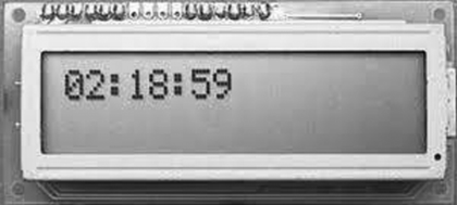
Figure 6.2 4 × 16 LCD display
The LCD normally has 14 pins for connection to the outside world. The pins are usually organised in a single row and numbered 1 to 14, as shown in Figure 6.3. Those with backlights have two additional pins. Table 6.1 shows the pin configuration. The device is normally operated from a voltage +3.3 to +5 V.
Figure 6.3 LCD pins
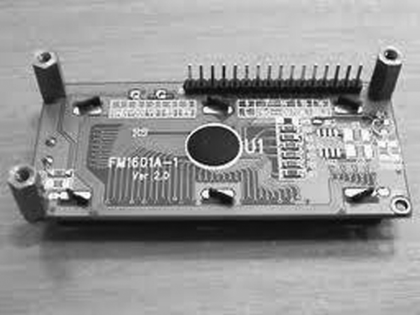
Table 6.1 LCD pin configuration.
| Pin no | Name | Function |
| 1 | Vss | Ground |
| 2 | Vdd | +V supply |
| 3 | Vee | Contrast adjustment |
| 4 | RS | Register select |
| 5 | R/W | Read/write |
| 6 | E | Enable (clock) |
| 7 | D0 | Data bit 0 |
| 8 | D1 | Data bit 1 |
| 9 | D2 | Data bit 2 |
| 10 | D3 | Data bit 3 |
| 11 | D4 | Data bit 4 |
| 12 | D5 | Data bit 5 |
| 13 | D6 | Data bit 6 |
| 14 | D7 | Data bit 7 |
| 15 (optional) | B+ | Backlight + |
| 16 (optional) | B− | Backlight − |
Vss is the ground pin. The Vdd pin should be connected to a positive supply. Although the manufacturers specify a +5 V supply, the device will work with as low as +3 V or as high as +6 V.
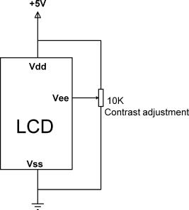
Pin 3 is named the Vee and this is the contrast adjustment pin. This pin is used to adjust the contrast of the display and it should be connected to a variable voltage supply. A 10 K potentiometer is normally connected between the power supply lines with its wiper arm connected to this pin so that the contrast can be adjusted as desired. Figure 6.4 shows a typical connection of this pin.
Figure 6.4 Adjusting the display contrast
Pin 4 is the Register Select (RS) and when this pin is LOW, any data sent to the display is treated as commands. When RS is HIGH, data sent is treated as character data for the display.
Pin 5 is the Read/write (R/W) line. This pin is pulled LOW in order to write commands or character data to the display (i.e. microcontroller to display data transfer). When this pin is HIGH, character data or status information can be read from the display module (i.e. display to microcontroller data transfer). The R/W pin is usually connected to ground, as we normally want to send commands and data to the display.
Pin 6 is the Enable (E) or clock pin used to initiate the transfer of command or data to the display. When writing to the display, data is transferred on the HIGH to LOW transition of this pin. Similarly, when reading from the display, data becomes available after the LOW to HIGH transition of this pin.
Pins 7 to 14 are the eight data bus lines (D0 to D7). As we shall see later, data transfer between the microcontroller and the LCD can take place using either 8-bit byte, or two 4-bit nibbles. In the latter case, only the upper 4 bits of the data bus pins (D4 to D7) are used and a byte is transferred in two successive operations. The advantage of using 4-bit mode is that fewer I/O lines are required to communicate with the LCD.
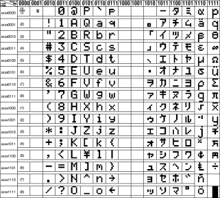
The LCD can display all of the standard ASCII characters. In addition, some symbols can also be displayed. Characters are made up of either 5 × 7 or 5 × 10 dots. Figure 6.5 shows the standard LCD character set, although different manufacturers can specify different character sets.
Figure 6.5 LCD standard character set
