4.3 Using the In-Circuit Debugger with the EasyPIC7 Development Board
We shall be using the EasyPIC7 development board in some of our projects in later chapters. It is therefore worthwhile to look at an example and see how we can use the in-circuit debugger on this board.
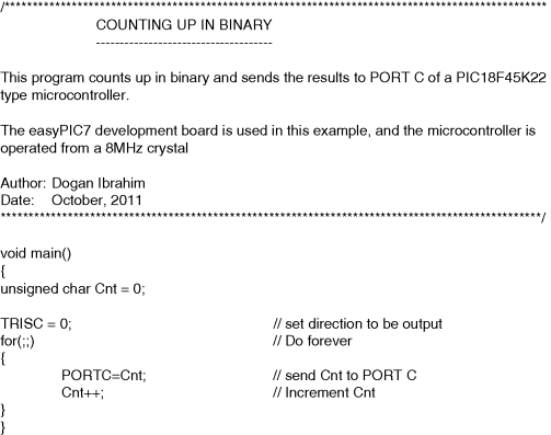
In this example we will count up in binary and send the results to PORT C of the microcontroller, where we will see the LEDs connected to the port counting up in binary. The required program code is shown in Figure 4.15. The steps to use the in-circuit debugger are given below:
- Create a project, as described in Chapter 3 and write the program given in Figure 4.15. Select the microcontroller type as PIC18F45K22, and the clock frequency as 8 MHz.
- Compile the program, making sure that the Build Type is set to ICD Debug and the Debugger is set to mikroICD in the Project Settings window before the compilation (see Figure 4.16).
- Connect the EasyPIC7 board to the PC using the USB cable, making sure that the power supply jumper is set to 5 V. You should see the green power LED and the orange Link LED turning ON.
- Download your program to the program memory of the microcontroller. Click Tools -> mE Programmer (or press function key F11) from the drop-down menu. During the loading you will see the red Active LED turn ON, and the Blue Data LED will flash to indicate that the loading is in progress.
- Start the in-circuit debugger by clicking Run -> Start Debugger (or press function key F9). When the debugging is started, the program line, which will be next executed, is highlighted with a blue strip at the left-hand side of the window (see Figure 4.17). On the right-hand side you will see the debug window.
- Let us single step through the program and monitor the values of variable Cnt. To do this, select variable Cnt from the list box named Select variable from list. Then, click Add button in window Watch Values. The variable to be monitored can now be seen, as in Figure 4.18.
- Press function key F8 to single step through the program. You should see the value of Cnt incrementing. At the same time, the PORT C LED pattern on the EasyPIC7 development board will increment in binary every time data is sent to the port. Figure 4.19 shows the debugging process when Cnt is 4.
- Stop the debugger by clicking Run -> Stop Debugger (or function keys CTRL + F2).
- The in-circuit debugger supports breakpoints, and the way breakpoints are set and cleared are the same as when we were using the simulator (see Section 3.7).
Figure 4.16 The Project Settings window
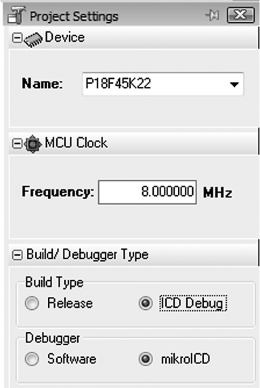
Figure 4.17 Program line to be executed next and the debug window
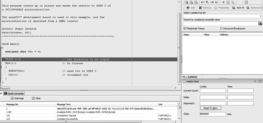
Figure 4.18 Monitoring variable Cnt
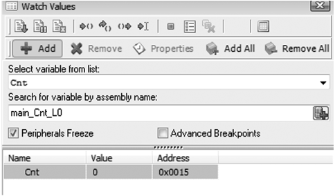
Figure 4.19 Debugging when Cnt is 4

It is interesting to note that the new version of the mikroC Pro for PIC compiler (Version 5.2) supports advanced breakpoint options, such as placing breakpoints at specified addresses in the program memory, stopping the code execution when read/write access to the specified data memory location occurs, event breakpoints, and so on.
Figure 4.15 Program for the example
