7.6 Adding Touch-screen to GLCDs
More and more consumer electronic products are now available with touch-screen inputs. For example, electronic games, MP3 players, GPS receivers, mobile phones, PDAs, ATM machines, industrial control systems, remote control devices, point-of-sale (POS) terminals, advertisement show screens, information displays, and many more similar products offer special screens where items are selected from a menu by simply touching the relevant part of the screen.
Perhaps the biggest advantage of a touch screen display is that it eliminates the need for keyboard input, resulting in a cheaper and lighter overall design. The user input facilities in such devices are usually provided in the form of soft keypads, where the layout of a keypad is displayed on a touch-screen panel, and the required characters and numbers can be entered by simply touching the required key positions on the touch screen. A soft keypad also makes it easier to enter and edit data quickly.
Another advantage of a touch-screen display is that it is usually much quicker to navigate around the screen than using a keyboard or mouse type inputs. Also, in some applications, such as GPS mapping and navigation, a desired geographical point can easily be selected by simply touching the desired point on the screen. It may take more time and effort to accurately select a point on a map using a keyboard and a mouse.
Touch-screen displays are also used in most POS systems, for example in restaurants and supermarket check-outs to select a purchased item from a menu quickly, easily and reliably. Perhaps the main advantage in such applications is the speed of making a correct selection.
Touch-screen displays have some disadvantages. Perhaps one of the greatest is that the screen may get dirty, oily, and finger prints can accumulate on the screen after long usage by the finger and as a result, it may become less sensitive to touch. Also, the screen can easily become scratched, especially if a hard object is used to touch and navigate through the screen. Touch screens can also cause stress on human fingers when used for more than a few minutes at a time, since pressure is required to make a selection. A touch device (e.g. a stylus) or fingernails can be used to prevent issues of direct touch. Another disadvantage is that a touch-screen LCD display is usually more expensive than a standard LCD display. The choice of whether or not to use a touch-screen display depends entirely on the nature of the application, the cost and the level of user experience.
7.6.1 Types of Touch-screen Displays
Touch-screen displays are in the form of either large screen monitors, used for example in PC systems, or small LCDs, used in microcontroller based systems. Although the principle of operation is the same in either case, in this book the small LCD type touch-screen displays are considered. Such displays usually have resolutions of 128 × 64 pixels and are used in battery operated intelligent devices.
A touch-screen LCD is basically a combination of a GLCD and a touch sensitive panel mounted on top of the GLCD. The two parts are independent of each other: The panel senses the co-ordinates where the user touches the screen, and the GLCD displays graphical information on the LCD display based upon the user's selection.
There are several types of touch-screen LCDs, such as resistive, capacitive, surface acoustic wave, optical imaging, strain gauge, and so on. The most commonly used are the resistive and capacitive types, and some information about each type is given below.
A resistive touch screen consists of several layers, where two electrically conductive resistive layers are separated by a very small gap and a flexible layer is used at the top. One of the layers is connected to a voltage source. When a point is pressed on the screen, the touched points of both conductive layers make a contact and if the voltage is read at the other layer, this voltage will be proportional to the position of the point touched because of the voltage dividing effect. Further details about resistive touch screens are given later.
A capacitive touch screen panel is coated with a material that stores electrical charges. When the panel is touched, a small amount of charge is drawn to the point of contact and the charge is measured at each corner of the panel and is then processed to determine the point touched.
Resistive touch screens have the advantages that the screen responds when touched with any kind of object, for example finger, stylus, nail, and so on. On the other hand, the capacitive screens respond only when touched by a naked finger (e.g. they will not respond when touched with an object or if wearing gloves). On the other hand, capacitive touch screens are lower power devices, have higher granularities, and also provide higher clarity.
Resistive touch screens are used in microcontroller based projects in later chapters in this book. Further information about resistive touch screens is given in the next section.
7.6.2 Resistive Touch Screens
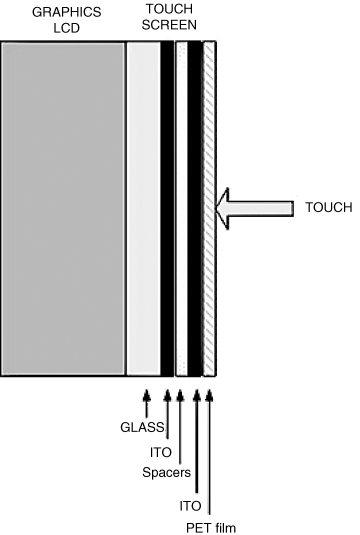
Resistive touch screens are used in most low cost, medium resolution systems. A resistive touch screen consists of at least three layers. As shown in Figure 7.8, the touch screen is mounted on a GLCD. The bottom layer is glass (or acryl), coated with a resistive Indium Tin Oxide (ITO) solution. On top of this, a resistive ITO coated poly Ethylene Terephthalate (PTE) flexible film is used. The two conductive ITO layers are separated from each other with microdot spacers, so that there is no contact between them when the screen is not touched. When a pressure is applied to the top of the screen, for example by touching the screen, the two ITO layers will make contact at the point of the touch. Electrical circuits are then used to determine the point of the contact. Usually a 4-wire, 5-wire or 8-wire circuit is used to determine the co-ordinates of the point touched by the user. These circuits are described below in greater detail.
Figure 7.8 Resistive touch screen
7.6.2.1 4-Wire Resistive Touch Screen
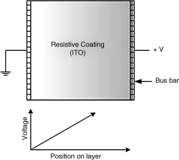
These are the least expensive and most commonly used types of resistive touch screens. Conductive bus bars with silver ink are implanted at the opposite edges of a screen layer. The principle of operation is such that, as shown in Figure 7.9, if one side of a layer is connected to +V and the other side to ground, a potential gradient results on the screen layer, and the voltage at any point on this layer becomes directly proportional to the distance from the +V side.
Figure 7.9 Voltage gradient in a screen layer
In a 4-wire touch screen, two measurements are made one after the other, to determine the X and Y co-ordinates of the point touched by the user. Figure 7.10a shows how the X co-ordinate can be determined. Here, the right- and left-hand sides of the top layer can be connected to +V and ground, respectively. The bottom layer can then be used to sense and measure the voltage at the point touched by the user. An A/D converter is used to convert this analogue voltage to digital and then to determine the X co-ordinate.
Figure 7.10 Determining the X and Y co-ordinates (4-wire). (a) Determining the X co-ordinate. (b) Determining the Y co-ordinate
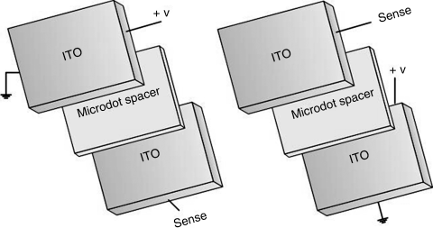
Similarly, Figure 7.10b shows how the Y co-ordinate can be determined. Here, the upper and lower sides of the bottom layer can be connected to +V and ground, respectively. The top layer can then be used to sense and measure the voltage at the point touched by the user. Again, an A/D converter is used to convert the voltage to digital and then to determine the Y co-ordinate.
7.6.2.2 5-Wire Resistive Touch Screen
This is a modification of the basic 4-wire system, where one layer (usually the top layer) is used for sensing and measuring the voltage, while the other layer is where the voltage gradient is created in X and Y directions. As shown in Figure 7.11a, to determine the X co-ordinate, the upper and lower sides of the bottom layer can be connected to +V and ground, respectively. The top layer is then used to sense and measure the voltage.
Figure 7.11 Determining the X and Y co-ordinates (5-wire). (a) Determining the X co-ordinate (b) Determining the Y co-ordinate
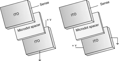
To determine the Y co-ordinate, we simply have to reverse polarity and sides of the bottom layer (see Figure 7.11b). The Y co-ordinate is then read from the top layer.
7.6.2.3 8-Wire Resistive Touch Screen
An 8-wire touch screen is used when more accurate measurements of the screen co-ordinates are required. In 4 and 5 wire implementations, the resistance of the bus bars and the connection circuitry usually introduce offset errors in voltage measurements. These offset errors can drift with temperature, humidity and time. 8-wire touch screens compensate for drift by adding 4 additional reference lines, thus enabling the voltage to be measured directly at the touch screen bus bars. 8-wire touch screens are generally more expensive than others and are not covered further in this book.
Example projects using the touch-screen GLCDs will be given in later chapters of this book.
