4.1 PIC Hardware Development Boards
Microcontroller development boards are available in many shapes and sizes. Some simple boards include a microcontroller, clock circuitry, power supply and a few LEDs. Some more advanced boards contain LCDs, graphics LCDs (GLCDs), push-button switches, USB ports, CAN bus ports, serial communication ports, in-circuit-debugging module, and so on.
Some of the commonly used development boards and their specifications are described in this section.
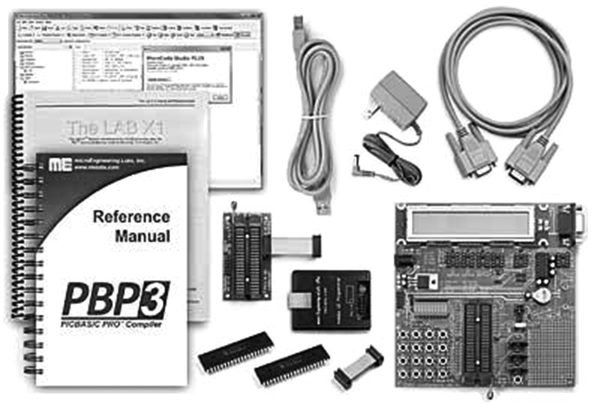
4.1.1 Super Bundle Development Kit
The Super Bundle development kit (see Figure 4.1), manufactured by microEngineering Labs Inc., is a complete integrated development board with the following features:
- PICBASIC PRO compiler;
- MicroCode Studio Plus integrated development environment with in-circuit debugger;
- LAB-X1 experimenter board with 5 V power supply, 40-pin ZIF socket, oscillator, reset circuit, LEDs, LCD, serial EEPROM, real-time clock, temperature sensor, servo drive, RS232/RS485 ports, IR interface, speaker and prototyping area;
- microcontroller programmer and programming adaptor;
- mains adaptor, USB cable and serial cable.
4.1.2 PIC18 Explorer Board
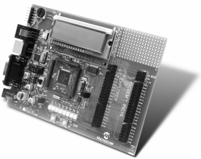
The PIC18 Explorer Board (see Figure 4.2) manufactured by Microchip Inc., can be used in the development of PIC18 microcontroller based projects. The board contains:
Figure 4.1 Super Bundle development kit. (Reproduced with permission from microEngineering Labs)
- sample PIC18F8722 and PIC18F87J11 (plug-in module) microcontrollers;
- 28–80 pin microcontroller support;
- LEDs and LCD display;
- expansion board connector (PICtail), enabling a large number of external boards to be connected;
- crystal oscillator;
- potentiometer (connected to A/D converter);
- USB and RS232 interface;
- programmable power supply;
- temperature sensor;
- MPLAB, ICD3 and REAL ICE connectors;
- SPI EEPROM;
- prototyping area.
4.1.3 PIC18F4XK20 Starter Kit
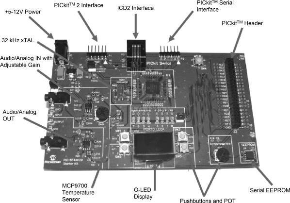
This board (see Figure 4.3) is manufactured by Microchip Inc., and can be used as a demonstration and learning board. The board contains
Figure 4.2 PIC18 Explorer board. (Reproduced with permission from Microchip Inc)
- PICkit 2 programmer/debugger;
- 128/64 Organic LED display;
- 32.768 kHz external clock;
- 4 push-button switches;
- 8 LEDs Serial EEPROM;
- daughter board (PICtail) for connecting external boards;
- potentiometer;
- Analogue in/out;
- ICD2 interface;
- temperature sensor.
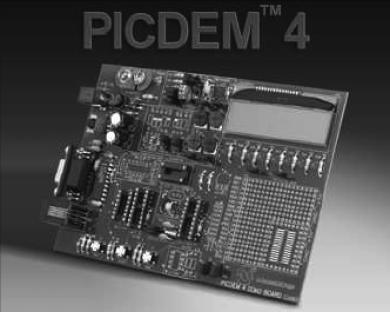
4.1.4 PICDEM 4
The PICDEM 4 board (see Figure 4.4), manufactured by Microchip Inc., can be used for developing 8-, 14- and 18-pin microcontroller based projects. The board contains:
Figure 4.3 PIC18F4XK20 Starter Kit. (Reproduced with permission from Microchip Inc)
- supporting 8-, 14- and 18-pin DIP devices;
- on-board +5 V regulator for direct input from AC/DC wall adaptor;
- RS-232 port;
- 8 LEDs;
- 2 × 16 LCD display;
- 3 push button switches and master reset;
- prototyping area;
- I/O Expander;
- supercapacitor circuitry;
- area for a LIN transceiver;
- area for a motor driver;
- MPLAB ICD 2 connector.
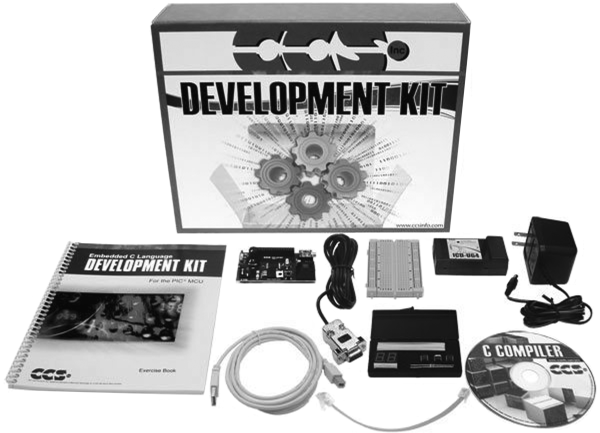
4.1.5 PIC16F887 Development Kit
This kit (see Figure 4.5) is manufactured by Custom Computer Services Inc. The kit includes an optional C compiler. The main features of this kit are:
Figure 4.4 PICDEM 4 development board. (Reproduced with permission from Microchip Inc)
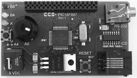
- PIC16F887 prototyping board (see Figure 4.6);
- 30 I/O pins;
- in-circuit debugger/programmer;
- potentiometer;
- push-button switch;
- RS232 converter;
- breadboard;
- serial EEPROM;
- real-time clock chip;
- digital temperature chip;
- two-digit 7-segment display;
- power supply.
Figure 4.6 PIC16F887 prototyping board
4.1.6 FUTURLEC PIC18F4550 Development Board
Although this board (see Figure 4.7) has been developed for USB based applications, it can be used in general microcontroller based project development. The board has the following features:
Figure 4.5 PIC16F887 development kit. (Reproduced with permission from Custom Computer Services Inc)
- includes PIC18F4550 Microcontroller;
- all necessary power supply components are pre-installed and board is ready-to-run;
- direct In-Circuit Program Download with the PIC Programmer or Microchip ICD2;
- 4 pushbuttons with Speaker;
- 4 variable potentiometers;
- 4 LEDs;
- large Breadboard area;
- USB and RS232 Connection;
- selectable PROG-RUN Switch;
- power and Programming LED;
- In-Circuit Debugging with Microchip ICD2 Unit.
4.1.7 EasyPIC6 Development Board
The EasyPIC6 development board (see Figure 4.8) is a sophisticated development board, manufactured by mikroElektronika. The board is fully integrated with the compilers developed by the company. Thus, a developed program can very easily be loaded to the program memory of the target microcontroller. In addition, the board contains an in-circuit debugger that can be used during the project development.
Figure 4.7 FUTURLEC PIC18F4550 development board. (Reproduced with permission from Futurlec Inc)
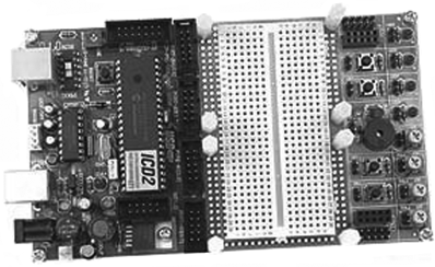
Figure 4.8 EasyPIC6 development board. (Reproduced with permission from mikroElectronika)

The main features of the EasyPIC6 development board are:
- support for over 160 PIC microcontrollers from 8- to 40-pin;
- 2 × 16 LCD and 2 × 16 COG (Chip-On-Glass) LCD;
- 128 × 64 GLCD;
- In-circuit debugger (mikroICD) and programmer;
- 4 × 4 keypad;
- USB communication port;
- 36 push-button switches;
- 36 LEDs External or USB power supply;
- digital thermometer;
- on board crystal oscillator;
- reset button;
- menu keypad;
- port expander circuit;
- 2 potentiometers for the analogue inputs;
- RS232 and PS/2 ports;
- all port pins available at IDC10 connectors.
4.1.8 EasyPIC7 Development Board
This is the latest development board (see Figure 4.9) from mikroElektronika, offering a large number of interface devices, and supporting over 250 PIC microcontroller types. The board is fully compatible and fully integrated with all the PIC microcontroller based compilers (mikroC Pro for PIC, mikroBASIC Pro for PIC, and mikroPASCAL Pro for PIC) offered by the company.
Figure 4.9 EasyPIC7 development board
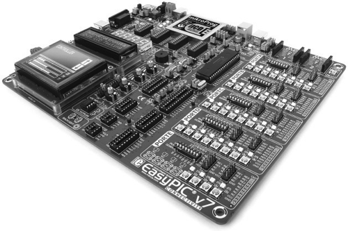
The main features of the EasyPIC7 development board are:
- support for over 250 PIC microcontrollers from 8- to 40-pin;
- 2 × 16 LCD;
- 128 × 64 GLCD with touch panel circuit;
- in-circuit debugger (mikroICD) and programmer;
- buzzer;
- digital (DS1820) and analogue (LM35) Temperature sensors;
- USB communication port;
- 36 push-button switches;
- 36 LEDs EEPROM;
- mikroBUS for connecting external boards;
- external or USB power supply;
- on board crystal oscillator;
- ICD2/ICD3 connector;
- external and USB dual power supply (5 V and 3.3 V);
- reset button;
- 4-digit 7-segment display;
- 2 potentiometers for the analogue inputs;
- tri-state DIP switches;
- RS232;
- all port pins available at IDC10 connectors.
