15.2 PROJECT 15.2 – Electronic Book
15.2.1 Project Description
This project describes the design of an electronic book, where a number of pages are displayed on the screen. In this project, there are three pages for simplicity. Two arrow shaped buttons are placed at the bottom of the display. Clicking the right-hand arrow displays the next page (unless it is the last page), while clicking the left-hand arrow displays the previous page (unless it is the first page).
The project is given the name BOOK. The MikroMMB board is used in the design, as in the previous project. The project configuration steps are as in the previous project, and only the changes are given here.
15.2.1.1 PAGE 1
Laboratories are a very important part of every engineering course. Students learn the theory in classes and apply their knowledge into practise by using real equipment in laboratory sessions. For example, electronic engineering students learn the complex theory of transistor amplifiers in the classroom.
15.2.1.2 PAGE 2
Simulation is an alternative to real experiments. In control engineering, Matlab is the most widely used software simulation tool. Students can create a model of the system to be simulated by using transfer function blocks, summing points, test inputs, and source and sink devices. The system model can then be simulated by applying inputs and observing the response graphically.
15.2.1.3 PAGE 3
Although laboratory experiments are very useful, they have some problems associated with them:
In the screen Properties window on the left, set screen colour to White, and orientation to Landscape. Click the Image tool and place it on the screen. Click next to Picture Name in Properties, and select the first page image of the book from the appropriate directory. Position the image to fit the screen. Next, click the Rounded Button tool and place a button at the bottom right-hand side of the image. Change the caption of this button to be ‘NEXT ->’, as shown in Figure 15.9.
Figure 15.9 Adding the first page image to the screen

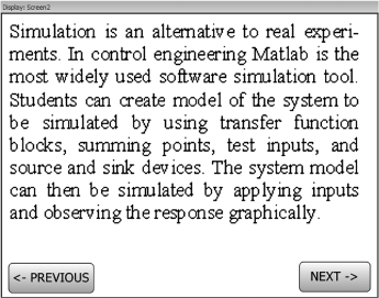
Now, create a new screen by clicking on the green ‘ + ’ Add Screen tool placed at the top of the menu. Set the screen colour to White and the orientation to Landscape as before. Add the second page image to the screen, and this time place two buttons at the bottom of the screen, as shown in Figure 15.10, so that we can navigate to the next or the previous screens.
Figure 15.10 Adding the second image to the screen
Finally, place the last page image and add a button, as shown in Figure 15.11, so that we can navigate back to the previous page.
![]()
Select Screen2 and click on ‘<- Previous’ button. Double click on ‘OnClick’ in the Properties window and enter the following code:
![]()
Similarly, click on the ‘NEXT ->’ button, double click on ‘OnClick’ in the Properties window and enter the following code, so that the third image is displayed when the button is pressed:
![]()
Finally, select Screen3 and click on ‘<- Previous’ button. Double click on ‘OnClick’ in the Properties window and enter the following code, so that the previous page image (image 2) is displayed when the button is clicked:
![]()
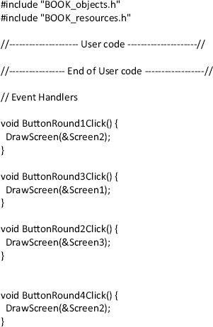
Figure 15.12 shows all the user action codes.
Figure 15.11 Adding the last image

Figure 15.12 User action codes
Click the icon ‘Start Compiler’ in the top menu to start the mikroC Pro for PIC compiler. Compile the program as before by clicking the ‘Build’ icon in the top menu. Load the program into the program memory of the microcontroller, using the Bootloader software as described in the previous project. Press the reset button on the display board to start the project. After calibrating the screen, you should see the first image displayed and you should be able to navigate to other images by clicking the appropriate buttons.
Figure 15.13 shows a typical display on the screen.
Figure 15.13 A typical display
