
14.1 PROJECT 14.1 – Toggle LED
14.1.1 Project Description
This is perhaps the simplest Visual GLCD based project. In this project, a standard GLCD with touch screen is used, as described in Chapter 13. An LED is connected to pin RC7 of the microcontroller and the LED is toggled when a shape is touched on the screen.
14.1.2 Block Diagram
The block diagram of the project is as shown in Figure 13.3.
The operation of the project is as follows: After power-up and screen calibration, the user can touch the TOGGLE LED box to turn ON the LED. Touching this box again will turn the LED OFF.
14.1.3 Circuit Diagram
The circuit diagram of the project is as shown in Figure 13.5. Standard 128 × 64 pixel GLCD is used in this project. Switching transistors are used as the touch screen controller. A PIC18F45K22 type microcontroller is used in the design with 8 MHz crystal.
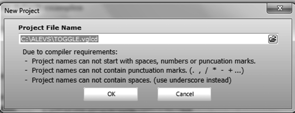
Figure 14.1 Specify the project name and project path
14.1.3.1 General (see Figure 14.2)
Figure 14.2 General settings
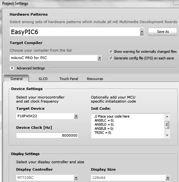
- Hardware patterns: EasyPIC6;
- Target Compiler: mikroC Pro for PIC PRO for PIC;
- Target Device: PIC18F45K22;
- Device Clock (Hz): 8 000 000;
- Configure PORT B, PORT C and PORT D as digital I/O, using the appropriate statements for the chosen microcontroller (e.g. use the ANSEL statements if using the PIC18F45K22 microcontroller), and configure PORT C as output in the ‘Init Code:’ section.
Notice here that the EasyPIC6 development board is used in the project, as this board uses the standard GLCD and touch screen to microcontroller interface.
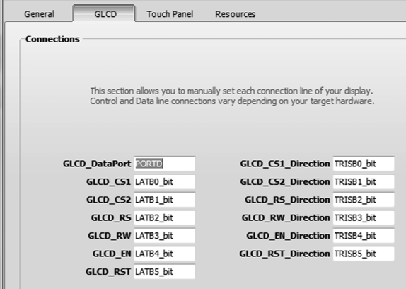
14.1.3.2 GLCD (see Figure 14.3)
| • GLCD_Data_Port: | PORTD | GLCD_CS1_Direction: TRISB0_bit |
| • GLCD_CS1: | LATB0_bit | GLCD_CS2_Direction: TRISB1_bit |
| • GLCD_CS2: | LATB1_bit | GLCD_RS_Direction: TRISB2_bit |
| • GLCD_RS: | LATB2_bit | GLCD_RW_Direction: TRISB3_bit |
| • GLCD_RW: | LATB3_bit | GLCD_EN_Direction: TRISB4_bit |
| • GLCD_EN: | LATB4_bit | GLCD_RST_Directiion:TRISB5_bit |
| • GLCD_RST: | LATB5_bit |
Figure 14.3 GLCD settings
14.1.3.3 Touch Panel (see Figure 14.4)
Figure 14.4 Touch Panel settings

![]()
You should also check the section ‘Init Code:’, to make sure that the entries are valid for the chosen microcontroller type.
Notice that the screen calibration can either be set as ‘Manual’ or ‘Preset’. In this project, the ‘Manual’ option is chosen so that the screen can be calibrated during the run time.
Figure 14.5 Name the screen as MainScreen
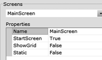
Figure 14.6 Adding Components onto the Screen
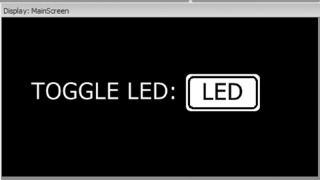
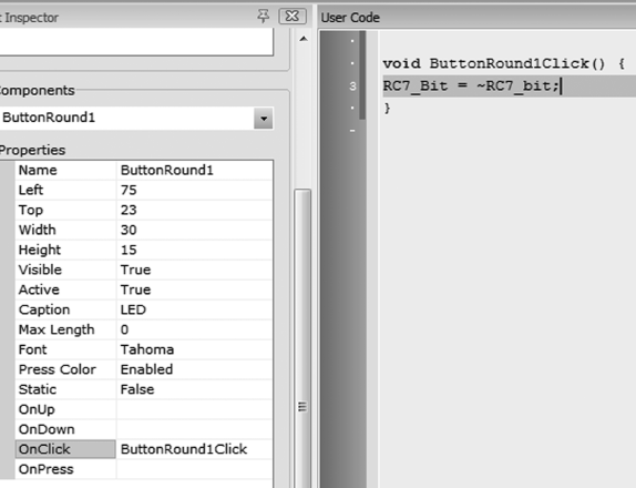
Figure 14.7 Add the code associated with the event
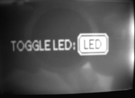
You should now see the display, as in Figure 14.8. The LED connected to pin RC7 should toggle as you click the ‘TOGGLE LED’ button. When the program is run, the user is asked initially to calibrate the screen by touching the appropriate points of the screen in response to prompts ‘TOUCH BOTTOM LEFT’ and ‘TOUCH UPPER RIGHT’.
Figure 14.8 Typical display when the program is run
The code generated by the Visual GLCD program is large and consists of three modules. Assuming the project name is TOGGLE, the following modules are generated:
- The main program: for example TOGGLE_main.C;
- Events code: for example TOGGLE_events_code.C;
- Driver program: for example TOGGLE_driver.C.
In addition, a number of include files are generated, for example TOGGLE_objects.h and TOGGLE_resources.h. The details of the generated files are beyond the scope of this book. Interested readers should consult the Visual GLCD documentation.