9.1 PROJECT 9.1 – Flashing LED
9.1.1 Project Description
This is perhaps the simplest project we can have. In this project, an LED is connected to bit 0 of PORT C (RC0) of a PIC18F45K22 type microcontroller (other PIC microcontrollers can also be used). The reason for using this microcontroller is because the EasyPIC 7 development board is equipped with this type of PIC microcontroller), operated from an 8 MHz crystal. The LED is flashed with 1 second intervals.
As described in Section 5.1, an LED is connected to a microcontroller using a current limiting resistor. An LED can be connected in two modes to a microcontroller output port: current sinking mode or current sourcing mode.
9.1.1.1 Current Sinking Mode
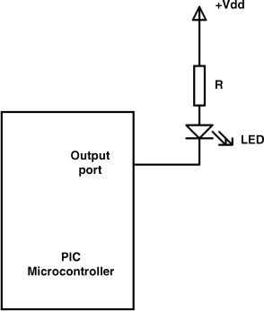
As shown in Figure 9.1, in current sinking mode the cathode of the LED is connected to the microcontroller I/O port, while the anode is connected to +5 V supply through a current limiting resistor. Here, the LED is turned ON when the output of the microcontroller is at logic LOW, where current flows into the microcontroller pin. The output current sink capability of each PIC microcontroller I/O pin is 25 mA. As was shown in Section 5.1, a 330 ohm or smaller resistor should give a current of about 10 mA, which is sufficient to drive the LED to give bright light.
Figure 9.1 LED connected in current sinking mode
9.1.1.2 Current Sourcing Mode
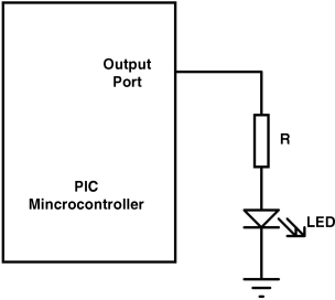
As shown in Figure 9.2, in current sourcing mode the anode of the LED is connected to the microcontroller I/O port, while the cathode is connected to the ground through a current limiting resistor. Here, the LED is turned ON when the output of the microcontroller is at logic HIGH, where current flows out of the microcontroller pin. The output current source capability of each PIC microcontroller I/O pin is 25 mA. As in the current sinking mode, a 330 ohm or smaller resistor should provide the required LED brightness.
Figure 9.2 LED connected in current sourcing mode
9.1.2 Block Diagram
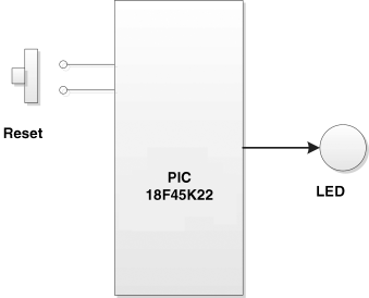
The block diagram of the project is shown in Figure 9.3.
Figure 9.3 Block diagram of the project
9.1.3 Circuit Diagram
The circuit diagram of the project is shown in Figure 9.4. If using the EasyPIC 7 development board, there is no need to change any jumper settings. An 8 MHz crystal is used to provide the clock signal. The microcontroller is Reset using an external push-button switch.
Figure 9.4 Circuit diagram of the project

9.1.4 Project PDL
The PDL of this project is very simple and is given in Figure 9.5.
Figure 9.5 PDL of the project

9.1.5 Project Program
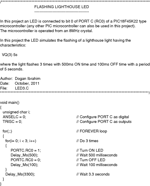
The program is named LED1.C and the program listing of the project is shown in Figure 9.6. At the beginning of the project, PORT C is configured as a digital I/O port by clearing register ANSELC (different PIC microcontrollers may require different settings). Then all the I/O ports of PORT C are set to be outputs by clearing the TRISC register. An endless for loop is then constructed and the LED is flashed with 1 second intervals using the Delay_Ms function with an argument of 1000 (i.e. 1 s). Notice that the individual bits of a port can be accessed as PORTn.Rnb, where n is the port name (A, B, C, D, etc.) and b is the bit number (0 to 7), or as PORTn.Fb, or as Rnb_bit. Thus, bit 0 of PORT C can either be accessed as PORTC.RC0, or as PORTC.F0, or as RC0_bit.
Figure 9.6 Program listing

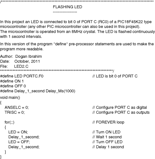
The program given in Figure 9.6 can be made more user friendly and easier to read if ‘#define’ pre-processor statements are used, as shown in program LED2.C in Figure 9.7.
Figure 9.7 More user friendly program
9.1.6 Suggestion for a Change
The program given in Figure 9.6 simply flashes the LED with 1 second intervals. This program can be modified, for example to simulate the flashing of lighthouse lights for maritime educational purposes. Different lighthouse lights have different flashing characteristics (see http://en.wikipedia.org/wiki/Light_characteristic), such as alternating, fixed, flashing, occulting, quick flash, very quick flash, and so on.
As an example, we shall modify the program to simulate the lighthouse signal known as
![]()
This signal consists of 3 short flashes, each 500 ms on and 100 ms off, and repeated every 5 seconds (see Figure 9.8). The PDL of the modified program is shown in Figure 9.9, and the program (named LED3.C) listing is shown in Figure 9.10. Notice that the period of the signal is 5 seconds. The 3 flashes take 1.7 seconds, leaving 3.3 seconds before the flashing starts again. The program contains a nested for loop. where the inner loop is repeated 3 times and the outer loop is repeated forever.
Figure 9.8 VQ(3) 10 s lighthouse signal

Figure 9.9 PDL of the modified program

Figure 9.10 Listing of the modified program
