10.3 PROJECT 10.3 – Display Lottery Numbers on 2-Digit 7-Segment LED Display
10.3.1 Project Description
In this project, a 2-digit 7-segment display is connected to PORT D of the microcontroller. The project displays 7 random lottery numbers between 1 and 49 with a 5-second interval between each number. The last number displayed is considered to be the ‘bonus’. A push-button switch is used to start the game. At the end of displaying all the 7 numbers, the display goes blank to indicate that the circuit is ready to start a new game.
In this project, the displays are refreshed inside a timer interrupt service routine in the background, so that the processor is free to do other tasks.
10.3.2 Block Diagram
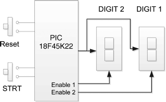
The block diagram of the project is shown in Figure 10.11. The 2-digit display pins a–g are connected in parallel and each digit is controlled separately. The push-button switch STRT starts the game.
Figure 10.11 Block diagram of the project
10.3.3 Circuit Diagram
The circuit diagram of the project is shown in Figure 10.12. The displays are connected in parallel to PORT D of the microcontroller. Each digit is enabled separately by connecting a transistor as a switch to its common cathode pin, as in the earlier project. Setting the base of the transistor to logic HIGH turns the transistor ON and enables the display. PORT A pins RA0 and RA1 are used to control the display enable lines. The STRT push-button switch is connected to pin RA2 of the microcontroller.
Figure 10.12 Circuit diagram of the project
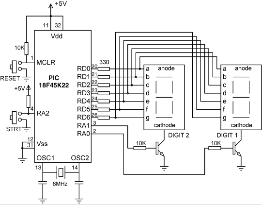
If you are using the EasyPIC 7 development board, then make sure you set to ON position switches SW4.1 (i.e. DIS0) and SW4.2 (i.e. DIS1), to enable the rightmost two digits of the 7-segment LED on the board.
10.3.4 Project PDL
The PDL of the project is given in Figure 10.13. The timer TMR0 is set to interrupt every 5 ms.
Figure 10.13 PDL of the project
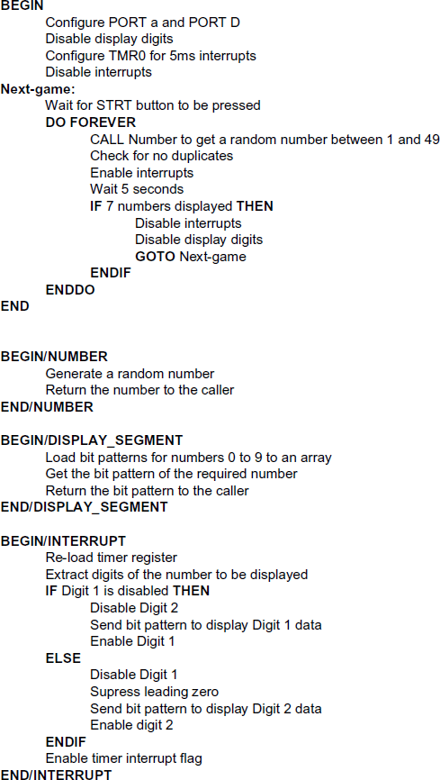
The interrupt priority feature is enabled by setting IPEN = 1 and the timer TMR0 interrupts are set to high-priority by setting TMR0IP = 1. The TMR0 interrupt flag is cleared by setting TMR0IF = 0, and the timer is set to operate in 8-bit mode, with a prescaler value of 64. As described in Chapter 2, the required timer value to generate interrupts every 5 ms (5000 μs) can be calculated from
(10.1) ![]()
or
(10.2) ![]()
giving TMR0L = 99.75; the nearest integer is selected, that is TMR0L = 100.
TMR0 interrupts are enabled by setting TMR0IE = 1. Finally, global interrupts are enabled by setting GIEH = 1. The timer is now ready to generate interrupts every 5 ms.
10.3.5 Project Program
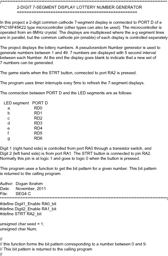
The program is named SEG4.C and the program listing of the project is given in Figure 10.14. At the beginning of the main program, Digit1_Enable, Digit2_Enable and STRT symbols are defined as bits RA0, RA1 and RA2 of PORT A, respectively. PORT D and PORT A are configured as digital I/O, PORT D pins, and RA0, RA1 of PORT A are configured as outputs, while RA2 is configure as input.
The two digits are disabled by clearing Digit1_Enable and Digit2_Enable to start with, so that the displays are blank at the beginning of the program.
The program then configures TMR0 to generate interrupts every 5 ms. IPEN is set to 1 to enable priority based interrupts, and TMR0 is set to high priority by setting TMR0IP bit to 1. TMR0 is configured to operate as an 8-bit timer with a prescaler of 64 and TMR0L is loaded with 100 in order to overflow at 5 ms intervals. TMR0 interrupts are enabled by setting bit TMR0IE bit. Global interrupts are not enabled (GIEH = 0) at this point in the program.
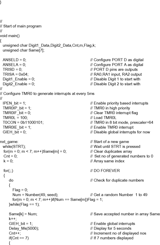
The program then waits until the STRT button is pressed. Normally this input pin is at logic 1 and pressing the button forces the RA2 pin to go to logic 0. When the button is pressed, the program clears all entries of an array called Same. This array is used to determine if duplicate numbers are generated and, if so, a new random number is generated.
The main part of the program starts in a for loop. Inside this loop, a new random lottery number is generated between 1 and 49 by calling function Number. The program then checks to make sure that this number was not generated before. Variable Flag is set if the number is duplicated and, if so, a new number is generated.
The program then enables global interrupts by setting bit GIEH of INTCON. The newly generated number is displayed for 5 seconds. At the end of this period, the program checks to see whether or not 7 numbers have been generated, and if not, the program continues inside the for loop to generate another number. If, on the other hand, 7 numbers have been generated so far, then interrupts are disabled (GIEH = 0) and the two display digits are also disabled to indicate the end of the game. At this point, the program jumps to label nxt_game and waits until the STRT button is pressed again to start a new game.
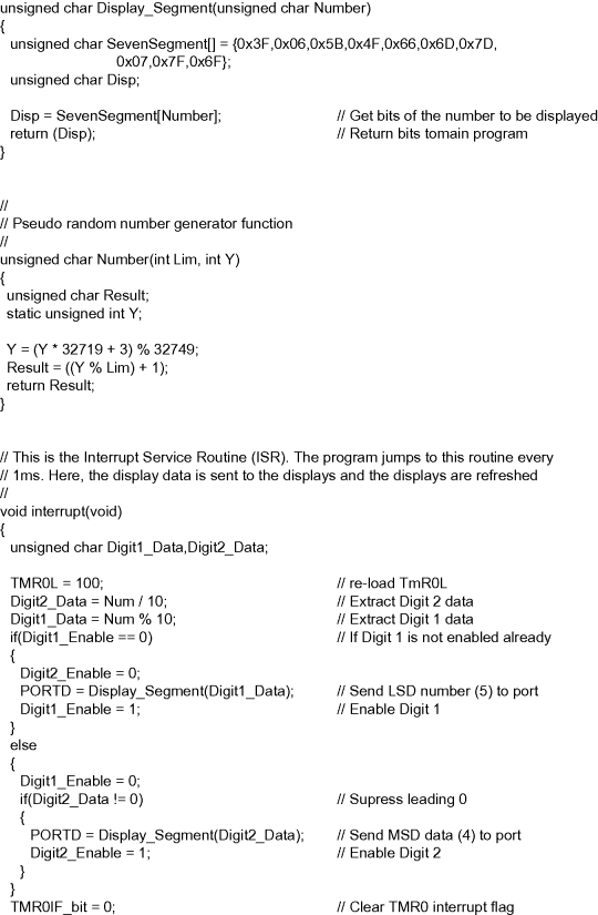
Function Display_Segment returns the bit pattern corresponding to a number to be displayed.
Function Number generates a pseudorandom number between 1 and 49 (a lottery number) every time it is called. The seed for the number is set outside the program loop, so that a different set of numbers are generated when the STRT button is pressed.
The timer interrupt service routine (ISR) is identified by a function called interrupt. Here, the timer register TMR0L is re-loaded with 100. Then the digits of the generated number Num are extracted and stored in variables Digit2_Data and Digit1_Data. Inside the ISR, only one of the display digits is enabled. For example, if, on the last entry to the ISR, Digit 1 was enabled, then on the next, the ISR Digit 2 will be enabled and so on. The program also makes sure that a leading zero is supressed. If the Digit 2 data is 0, then this digit is disabled so that the leading zero is not shown.
Timer interrupt flag TMR0IF is re-enabled just before exiting the ISR, so that further timer interrupts can be accepted by the microcontroller.
