
Identifying Purposes and Characteristics of Cooling Systems
It’s a basic concept of physics: Electronic components turn electricity into work and heat. The excess heat must be dissipated or it will shorten the life of the components. In some cases (like with the CPU), the component will produce so much heat that it can destroy itself in a matter of seconds if there is not some way to remove this extra heat.
Air-cooling methods are used to cool the internal components of most PCs. With air cooling, the movement of air removes the heat from the component. Sometimes, large blocks of metal called heat sinks are attached to a heat-producing component in order to dissipate the heat more rapidly.
Fans
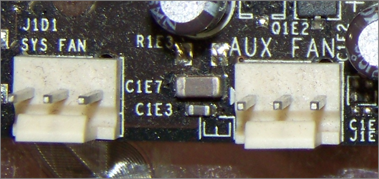
When you turn on a computer, you will often hear lots of whirring. Contrary to popular opinion, the majority of the noise isn’t coming from the hard disk (unless it’s about to go bad). Most of this noise is coming from the various fans inside the computer. Fans provide airflow within the computer.
Most PCs have a combination of these seven fans:
Ideally, the airflow inside a computer should resemble what is shown in Figure 1-27.
Figure 1-27: System unit airflow
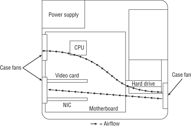
Note that you must pay attention to the orientation of the power supply’s airflow. If the power supply fan is an exhaust fan, as assumed in this discussion, the front and rear fans will match their earlier descriptions: front, intake; rear, exhaust. If you run across a power supply that has an intake fan, the orientation of the supplemental chassis fans should be reversed as well. The rear chassis fan(s) should always be installed in the same orientation as the power supply fan runs to avoid creating a small airflow circuit that circumvents the cross flow of air through the case. The front chassis fan and the rear fans should always be installed in the reverse orientation to avoid them fighting against each other and reducing the internal airflow. Reversing supplemental chassis fans is usually no harder than removing four screws and flipping the fan. Sometimes, the fan might just snap out, flip, and then snap back in, depending on the way it is rigged up.
Memory Cooling
If you are going to start overclocking your computer, you will want to do everything in your power to cool all its components, and that includes the memory.
There are two methods of cooling memory: passive and active. The passive memory cooling method just uses the ambient case airflow to cool the memory through the use of enhanced heat dissipation. For this, you can buy either heat sinks or, as mentioned earlier, special “for memory chips only” devices known as heat spreaders. Recall that these are special aluminum or copper housings that wrap around memory chips and conduct the heat away from them.
Active cooling, on the other hand, usually involves forcing some kind of cooling medium (air or water) around the RAM chips themselves or around their heat sinks. Most often, active cooling methods are just high-speed fans directing air right over a set of heat spreaders.
Hard Drive Cooling
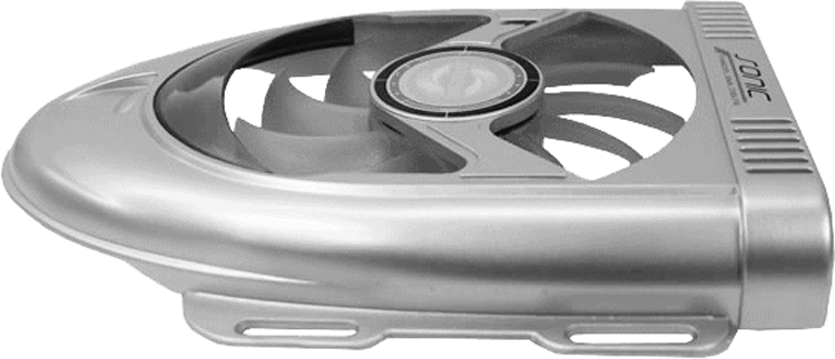
You might be thinking, “Hey, my hard drive is doing work all the time. Is there anything I can do to cool it off?” There are both active and passive cooling devices for hard drives. Most common, however, is the active cooling bay. You install a hard drive in a special device that fits into a 51 ⁄4 ″ expansion bay. This device contains fans that draw in cool air over the hard drive, thus cooling it. Figure 1-28 shows an example of one of these active hard drive coolers. As you might suspect, you can also get heat sinks for hard drives.
Figure 1-28: An active hard disk cooler
Chipset Cooling
Every motherboard has a chip or chipset that controls how the computer operates. As with other chips in the computer, the chipset is normally cooled by the ambient air movement in the case. However, when you overclock a computer, the chipset may need to be cooled more because it is working harder than it normally would be. Therefore, it is often desirable to replace the onboard chipset cooler with a more efficient one. Refer back to Figure 1-2 for a look at a modern chipset cooling solution.
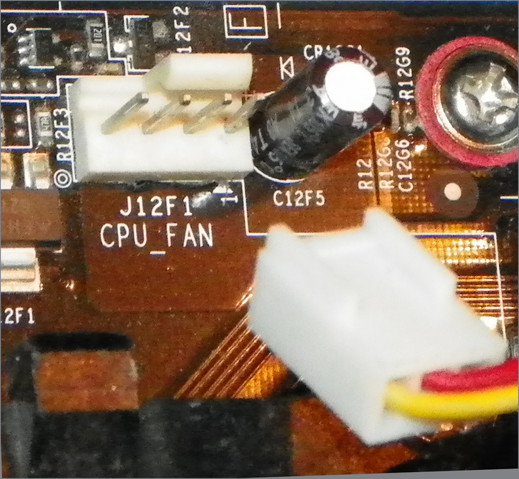
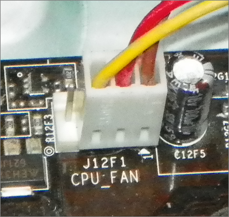
CPU Cooling
Probably the greatest challenge in cooling is the cooling of the computer’s CPU. It is the component that generates the most heat in a computer (aside from some pretty insane GPUs out there). As a matter of fact, if a modern processor isn’t actively cooled all the time, it will generate enough heat to burn itself up in an instant. That’s why most motherboards have an internal CPU heat sensor and a CPU_FAN sensor. If no cooling fan is active, these devices will shut down the computer before damage occurs.
There are a few different types of CPU cooling methods, but the most important can be grouped into two broad categories: air cooling and advanced cooling methods.
Air Cooling
The parts inside most computers are cooled by air moving through the case. The CPU is no exception. However, because of the large amount of heat produced, the CPU must have (proportionately) the largest surface area exposed to the moving air in the case. Therefore, the heat sinks on the CPU are the largest of any inside the computer.
The CPU fan often blows air down through the body of the heat sink to force the heat into the ambient internal air where it can join the airflow circuit for removal from the case. However, in some cases, you might find that the heat sink extends up farther, using radiator-type fins, and the fan is placed at a right angle and to the side of the heat sink. This design moves the heat away from the heat sink immediately instead of pushing the air down through the heat sink. CPU fans can be purchased that have an adjustable rheostat to allow you to dial in as little airflow as you need, aiding in noise reduction but potentially leading to accidental overheating.
It should be noted that the highest-performing CPU coolers use copper plates in direct contact with the CPU. They also use high-speed and high-CFM cooling fans to dissipate the heat produced by the processor. CFM is short for cubic feet per minute, an airflow measurement of the volume of air that passes by a stationary object per minute.
Most new CPU heat sinks use tubing to transfer heat away from the CPU. With any cooling system, the more surface area exposed to the cooling method, the better the cooling. Plus, the heat pipes can be used to transfer heat to a location away from the heat source before cooling. This is especially useful in cases where the form factor is small and with laptops, where open space is limited.
With advanced heat sinks and CPU cooling methods like this, it is important to improve the thermal transfer efficiency as much as possible. To that end, cooling engineers came up with a compound that helps to bridge the extremely small gaps between the CPU and the heat sink, which avoids superheated pockets of air that can lead to focal damage of the CPU. This product is known as thermal transfer compound or simply thermal compound (alternatively, thermal grease or thermal paste) and can be bought in small tubes. Single-use tubes are also available and alleviate the guesswork involved with how much you should apply. Watch out, though; this stuff makes quite a mess and doesn’t want to come off your fingers very easily.
Apply the compound by placing a bead in the center of the heat sink, not on the CPU, because some heat sinks don’t cover the entire CPU package. That might sound like a problem, but some CPUs don’t have heat-producing components all the way out to the edges. Some CPUs even have a raised area directly over where the silicon die is within the packaging, resulting in a smaller contact area between the components. You should apply less than you think you need because the pressure of attaching the heat sink to the CPU will spread the compound across the entire surface in a very thin layer. It’s advisable to use a clean, lint-free applicator of your choosing to spread the compound around a bit as well, just to get the spreading started. You don’t need to concern yourself with spreading it too thoroughly or too neatly because the pressure applied during attachment will equalize the compound quite well. During attachment, watch for oozing compound around the edges, clean it off immediately, and use less next time.
If you’ve ever installed a brand-new heat sink onto a CPU, you’ve most likely used thermal compound or the thermal compound patch that was already applied to the heat sink for you. If your new heat sink has a patch of thermal compound preapplied, don’t add more. If you ever remove the heat sink, don’t try to reuse the patch or any other form of thermal compound. Clean it all off and start fresh.
Advanced CPU Cooling Methods
Advancements in air cooling have led to products like the Scythe Ninja series, which is a stack of thin aluminum fins with copper tubing running up through them. Some of the hottest-running CPUs can be passively cooled with a device like this, using only the existing air-movement scheme from your computer’s case. Adding a fan to the side, however, adds to the cooling efficiency but also to the noise level, even though Scythe calls this line Ninja because of how quiet it is.
In addition to standard and advanced air-cooling methods, there are other methods of cooling a CPU (and other chips as well). These methods might appear somewhat unorthodox but often deliver extreme results.
Liquid Cooling
Liquid cooling is a technology whereby a special water block is used to conduct heat away from the processor (as well as from the chipset). Water is circulated through this block to a radiator, where it is cooled.
The theory is that you could achieve better cooling performance through the use of liquid cooling. For the most part, this is true. However, with traditional cooling methods (which use air and water), the lowest temperature you can achieve is room temperature. Plus, with liquid cooling, the pump is submerged in the coolant (generally speaking), so as it works, it produces heat, which adds to the overall liquid temperature.
The main benefit to liquid cooling is silence. There is only one fan needed: the fan on the radiator to cool the water. So a liquid-cooled system can run extremely quietly.
Liquid cooling, while more efficient than air cooling and much quieter, has its drawbacks. Most liquid-cooling systems are more expensive than supplemental fan sets, and require less familiar components, such as reservoir, pump, water block(s), hose, and radiator.
The relative complexity of installing liquid cooling systems, coupled with the perceived danger of liquids in close proximity to electronics, leads most computer owners to consider liquid cooling a novelty or a liability. The primary market for liquid cooling is the high-performance niche that engages in overclocking to some degree. However, developments in active air cooling, including extensive piping of heat away from the body of the heat sink, have kept advanced cooling methods out of the forefront. Nevertheless, advances in fluids with safer electrolytic properties and even viscosities keep liquid cooling viable.
Heat Pipes
Heat pipes are closed systems that employ some form of tubing filled with a liquid suitable for the applicable temperature range. Pure physics are used with this technology to achieve cooling to ambient temperatures; no outside mechanism is used. One end of the heat pipe is heated by the component being cooled. This causes the liquid at the heated end to evaporate and increase the relative pressure at that end of the heat pipe with respect to the cooler end. This pressure imbalance causes the heated vapor to equalize the pressure by migrating to the cooler end, where the vapor condenses and releases its heat, warming the nonheated end of the pipe. The cooler environment surrounding this end transfers the heat away from the pipe by convection. The condensed liquid drifts to the pipe’s walls and is drawn back to the heated end of the heat pipe by gravity or by a wicking material or texture that lines the inside of the pipe. Once the liquid returns, the process repeats.
Peltier Cooling Devices
Water- and air-cooling devices are extremely effective by themselves, but they are more effective when used with a device known as a Peltier cooling element. These devices, also known as thermoelectric coolers (TECs), facilitate the transfer of heat from one side of the element, made of one material, to the other side, made of a different material. Thus, they have a hot side and a cold side. The cold side should always be against the CPU surface, and optimally, the hot side should be mated with a heat sink or water block for heat dissipation. Consequently, TECs are not meant to replace air-cooling mechanisms but to complement them.
One of the downsides to TECs is the likelihood of condensation because of the subambient temperatures these devices produce. Closed-cell foams can be used to guard against damage from condensation.
Phase-Change Cooling
With phase-change cooling, the cooling effect from the change of a liquid to a gas is used to cool the inside of a PC. It is a very expensive method of cooling, but it does work. Most often, external air-conditioner-like pumps, coils, and evaporators cool the coolant, which is sent, ice cold, to the heat sink blocks on the processor and chipset. Think of it as a water-cooling system that chills the water below room temperature. Unfortunately, this is easily the noisiest cooling method in this discussion. Its results cannot be ignored, however; it is possible to get CPU temps in the range of –4° F (–20° C). Normal CPU temperatures hover between 104° F and 122° F (40° C and 50° C).
The major drawback to this method is that in higher-humidity conditions, condensation can be a problem. The moisture from the air condenses on the heat sink and can run off onto and under the processor, thus shorting out the electronics. Designers of phase-change cooling systems offer solutions to help ensure that this isn’t a problem. Products in the form of foam; silicone adhesive; and greaseless, noncuring adhesives are available to seal the surface and perimeter of the processor. Additionally, manufacturers sell gaskets and shims that correspond to specific processors, all designed to protect your delicate and expensive components from damage.
Liquid Nitrogen and Helium Cooling
In the interest of completeness, there is a novel approach to super-cooling processors that is ill-advised under all but the most extreme circumstances. By filling a vessel placed over the component to be cooled with a liquid form of nitrogen or, for an even more intense effect, helium, temperatures from –100° C to –240° C can be achieved. The results are short lived and only useful in overclocking with a view to setting records. The processor is not likely to survive the incident, due to the internal stress from the extreme temperature changes as well as the stress placed on the microscopic internal joints by the passage of excessive electrons.
Undervolting
Not an attachment, undervolting takes advantage of the property of physics whereby reduction in voltage has an exponential effect on the reduction of power consumption and associated heat production. Undervolting requires a BIOS (where the setting is made) and CPU combination that supports it.
You should monitor the system for unpredictable adverse effects. One of your troubleshooting steps might include returning the CPU voltage to normal and observing the results.