
Understanding Networking Principles
Stand-alone personal computers, first introduced in the late 1970s, gave users the ability to create documents, spreadsheets, and other types of data and save them for future use. For the small-business user or home-computer enthusiast, this was great. For larger companies, however, it was not enough. Larger companies had greater needs to share information between offices and sometimes over great distances. Stand-alone computers were insufficient for the following reasons:
- Their small hard-drive capacities were insufficient.
- To print, each computer required a printer attached locally.
- Sharing documents was cumbersome. People grew tired of having to save to a floppy and then take that disk to the recipient. (This procedure was called sneakernet.)
- There was no email. Instead, there was interoffice mail, which was slow and unreliable.
To address these problems, networks were born. A network links two or more computers together to communicate and share resources. Their success was a revelation to the computer industry as well as businesses. Now, departments could be linked internally to offer better performance and increase efficiency.
You have probably heard the term networking in a business context, where people come together and exchange names for future contact and to give them access to more resources. The same is true with a computer network. A computer network allows computers to link to each other’s resources. For example, in a network, every computer does not need a printer connected locally in order to print. Instead, you can connect a printer to one computer or directly to the network and allow all of the other computers to access this resource. Because they allow users to share resources, networks can increase productivity as well as decrease cash outlay for new hardware and software.
In the following sections, we will discuss the fundamentals of networking as well as types of networks you are likely to encounter.
Understanding Networking Fundamentals
In many cases, networking today has become a relatively simple plug-and-play process. Wireless network cards can automatically detect and join networks and you’re seconds away from surfing the Web or sending email. Of course, not all networks are that simple. Getting your network running may require a lot of configuration, and one messed-up setting can cause the whole thing to fail.
Just as there is a lot of information to know about how to configure your network, there is a lot of background information you should understand about how networks work. The following sections cover the fundamentals, and armed with this information, you can then move on to how to make it work right. The following basics are covered here:
- LANs, WANs, PANs, and MANs
- Primary network components
- Network operating systems (NOSs)
- Network resource access
- Network topologies
- Rules of communication
LANs, WANs, PANs, and MANs
Local area networks (LANs) were introduced to connect computers in a single office or building. Wide area networks (WANs) expanded the LANs to include networks outside the local environment and also to distribute resources across long distances. Generally, it’s safe to think of a WAN as multiple, disbursed LANs connected together. Today, LANs exist in many homes (wireless networks) and nearly all businesses. WANs are becoming more common as businesses become more mobile and as more of them span greater distances. WANs were historically used only by larger corporations, but many smaller companies with remote locations now use them as well.
Having two types of network categories just didn’t feel like enough, so the industry introduced two more terms. The personal area network (PAN) is a very small-scale network designed around one person. The term generally refers to networks using Bluetooth technology. On a larger scale is the metropolitan area network (MAN), which is bigger than a LAN but not quite as big as a WAN.
It is important to understand these concepts as a service professional because when you’re repairing computers, you are likely to come in contact with problems that are associated with the computer’s connection to a network. Understanding the basic structure of the network can often help you solve a problem.
LANs
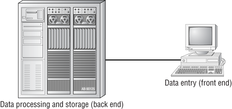
The 1970s brought us the minicomputer, which was a smaller version of the mainframe. Whereas the mainframe used centralized processing (all programs ran on the same computer), the minicomputer used distributed processing to access programs across other computers. As depicted in Figure 6-1, distributed processing allows a user at one computer to use a program on another computer as a back end to process and store information. The user’s computer is the front end, where data entry and minor processing functions are performed. This arrangement allowed programs to be distributed across computers rather than centralized. This was also the first time network cables rather than phone lines were used to connect computers.
Figure 6-1: Distributed processing
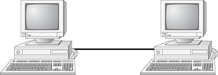
By the 1980s, offices were beginning to buy PCs in large numbers. Portables were also introduced, allowing computing to become mobile. Neither PCs nor portables, however, were efficient in sharing information. As timeliness and security became more important, floppy disks were just not cutting it. Offices needed to find a way to implement a better means to share and access resources. This led to the introduction of the first type of PC local area network (LAN): ShareNet by Novell, which had both hardware and software components. LANs are simply the linking of computers to share resources within a closed environment. The first simple LANs were constructed a lot like the LAN in Figure 6-2.
Figure 6-2: A simple LAN
After the introduction of ShareNet, more LANs sprouted. The earliest LANs could not cover large distances. Most of them could only stretch across a single floor of the office and could support no more than 30 users. Further, they were still very rudimentary and only a few software programs supported them. The first software programs that ran on a LAN were not capable of being used by more than one user at a time (this constraint was known as file locking). Nowadays, we can see multiple users accessing a program or file at one time. Most of the time, the only limitations will be restrictions at the record level if two users are trying to modify a database record at the same time.
WANs
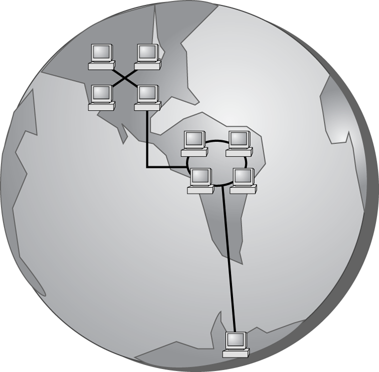
By the late 1980s, networks were expanding to cover large geographical areas and were supporting thousands of users. Wide area networks (WANs), first implemented with mainframes at massive government expense, started attracting PC users as networks went to this new level. Employees of businesses with offices across the country communicated as if they were only desks apart. Soon the whole world saw a change in the way of doing business, across not only a few miles but across countries. Whereas LANs are limited to single buildings, WANs can span buildings, states, countries, and even continental boundaries. Figure 6-3 gives an example of a simple WAN.
Networks of today and tomorrow are no longer limited by the inability of LANs to cover distance and handle mobility. WANs play an important role in the future development of corporate networks worldwide.
PANs
In 1998, a consortium of companies formed the Bluetooth Special Interest Group (SIG) and formally adopted the name Bluetooth for its technology. The name comes from a tenth-century Danish king named Harald Blåtand, known as Harold Bluetooth in English. (One can only imagine how he got that name.) King Blåtand had successfully unified warring factions in the areas of Norway, Sweden, and Denmark. The makers of Bluetooth were trying to unite disparate technology industries, namely computing, mobile communications, and the auto industry.
Figure 6-3: A simple WAN
Current membership in the Bluetooth SIG includes Microsoft, Intel, Apple, IBM, Toshiba, and several cell phone manufacturers. The technical specification IEEE 802.15.1 describes a wireless personal area network (WPAN) based on Bluetooth version 1.1.
The first Bluetooth device on the market was an Ericsson headset and cell phone adapter, which arrived on the scene in 2000. While mobile phones and accessories are still the most common type of Bluetooth device, you will find many more including wireless keyboards, mice, and printers. Figure 6-4 shows a Bluetooth USB adapter.
Figure 6-4: Bluetooth USB adapter


One of the unusual features of a Bluetooth WPAN is its temporary nature. With other popular wireless standards, you need a central communication point, such as a hub or router. Bluetooth networks are formed on an ad hoc basis, meaning that whenever two Bluetooth devices get close enough to each other, they can communicate directly with each other. This dynamically created network is called a piconet. A Bluetooth-enabled device can communicate with up to seven other devices in one piconet. Two or more piconets can be linked together in a scatternet. In a scatternet, one or more devices would serve as a bridge between the piconets.
MANs
For those networks that are larger than a LAN but confined to a relatively small geographical area, there is the term metropolitan area network (MAN). A MAN is generally defined as a network that spans a city or a large campus. For example, if a city decides to install wireless hotspots in various places, that network could be considered a MAN.
One of the questions a lot of people ask is, “Is there really a difference between a MAN and a WAN?” There is definitely some gray area here; in many cases they are virtually identical. Perhaps the biggest difference is who has responsibility for managing the connectivity. In a MAN, a central IT organization such as the campus or city IT staff is responsible. In a WAN, it’s implied that you will be using publicly available communication lines and there will be a phone company or other service provider involved.
Primary Network Components
Technically speaking, two or more computers connected together constitute a network. But networks are rarely that simple. When you’re looking at the devices or resources available on a network, there are three types of components to be aware of:
- Servers
- Clients or workstations
- Resources
Servers
Servers come in many shapes and sizes. They are a core component of the network, providing a link to the resources necessary to perform any task. The link the server provides could be to a resource existing on the server itself or a resource on a client computer. The server is the critical enabler, offering directions to the client computers regarding where to go to get what they need.
Servers offer networks the capability of centralizing the control of resources and security, thereby reducing administrative difficulties. They can be used to distribute processes for balancing the load on computers and can thus increase speed and performance. They can also compartmentalize files for improved reliability. That way, if one server goes down, not all of the files are lost.
Servers can perform several different critical roles on a network. For example, servers that provide files to the users on the network are called file servers. Likewise, servers that host printing services for users are called print servers. (Servers can be used for other tasks as well, such as authentication, remote access services, administration, email, and so on.) Networks can include multipurpose and single-purpose servers. A multipurpose server can be, for example, both a file server and a print server at the same time. If the server is a single-purpose server, it is a file server only or a print server only. Another distinction we use in categorizing servers is whether they are dedicated or nondedicated:
Many networks use both dedicated and nondedicated servers to incorporate the best of both worlds, offering improved network performance with the dedicated servers and flexibility with the nondedicated servers.
Workstations
Workstations are the computers on which the network users do their work, performing activities such as word processing, database design, graphic design, email, and other office or personal tasks. Workstations are basically everyday computers, except for the fact that they are connected to a network that offers additional resources. Workstations can range from diskless computer systems to desktops or laptops. In network terms, workstations are also known as client computers. As clients, they are allowed to communicate with the servers in the network to use the network’s resources.
It takes several items to make a workstation into a network client. You must install a network interface card (NIC), a special expansion card that allows the PC to talk on a network. You must connect it to a cabling system that connects to other computers (unless your NIC supports wireless networking). And you must install special software, called client software, which allows the computer to talk to the servers and request resources from them. Once all this has been accomplished, the computer is “on the network.”
To the client, the server may be nothing more than just another drive letter. However, because it is in a network environment, the client can use the server as a doorway to more storage or more applications or to communicate with other computers or other networks. To users, being on a network changes a few things:
- They can store more information because they can store data on other computers on the network.
- They can share and receive information from other users, perhaps even collaborating on the same document.
- They can use programs that would be too large or complex for their computer to use by itself.
- They can use hardware not attached directly to their computer, such as a printer.
Network Resources
We now have the server to share the resources and the workstation to use them, but what about the resources themselves? A resource (as far as the network is concerned) is any item that can be used on a network. Resources can include a broad range of items, but the following items are among the most important:
- Printers and other peripherals
- Disk storage and file access
- Applications
When an office has to purchase only a few printers (and all of the associated consumables) for the entire office, the costs are dramatically lower than the costs for supplying printers at every workstation.
Networks also give users more storage space to store their files. Client computers can’t always handle the overhead involved in storing large files (for example, database files) because they are already heavily involved in users’ day-to-day work activities. Because servers in a network can be dedicated to only certain functions, a server can be allocated to store all the larger files that are worked with every day, freeing up disk space on client computers. In addition, if users store their files on a server, the administrator can back up the server periodically to ensure that if something happens to a user’s files, those files can be recovered.
Files that all users need to access (such as emergency contact lists and company policies) can also be stored on a server. Having one copy of these files in a central location saves disk space as opposed to storing the files locally on everyone’s system.
Applications (programs) no longer need to be on every computer in the office. If the server is capable of handling the overhead an application requires, the application can reside on the server and be used by workstations through a network connection.
Network Operating Systems (NOSs)
PCs use a disk operating system that controls the file system and how the applications communicate with the hard disk. Networks use a network operating system (NOS) to control the communication with resources and the flow of data across the network. The NOS runs on the server. Some of the more popular NOSs include UNIX and Linux and Microsoft’s Windows Server series (Server 2008, Server 2003, etc.). Several other companies offer network operating systems as well.
Network Resource Access
We have discussed two major components of a typical network, servers and workstations, and we’ve also talked briefly about network resources. Let’s dive in a bit deeper on how those resources are accessed on a network.
There are generally two resource access models: peer-to-peer and client-server. It is important to choose the appropriate model. How do you decide what type of resource model is needed? You must first think about the following questions:
- What is the size of the organization?
- How much security does the company require?
- What software or hardware does the resource require?
- How much administration does it need?
- How much will it cost?
- Will this resource meet the needs of the organization today and in the future?
- Will additional training be needed?
Networks cannot just be put together at the drop of a hat. A lot of planning is required before implementation of a network to ensure that whatever design is chosen will be effective and efficient, and not just for today but for the future as well. The forethought of the designer will lead to the best network with the least amount of administrative overhead. In each network, it is important that a plan be developed to answer the previous questions. The answers will help the designer choose the type of resource model to use.
Peer-to-Peer Networks
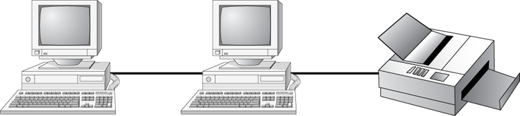
In a peer-to-peer network, the computers act as both service providers and service requestors. An example of a peer-to-peer resource model is shown in Figure 6-5.
Figure 6-5: The peer-to-peer resource model
Peer-to-peer networks are great for small, simple, inexpensive networks. This model can be set up almost immediately, with little extra hardware required. Many versions of Windows (Windows 7, Vista, XP, 2000), Linux, and Mac OS are popular operating system environments that support a peer-to-peer resource model. Peer-to-peer networks are also referred to as workgroups.
Generally speaking, there is no centralized administration or control in the peer-to-peer resource model. Every station has unique control over the resources the computer owns, and each station must be administered separately. However, this very lack of centralized control can make it difficult to administer the network; for the same reason, the network isn’t very secure. Moreover, because each computer is acting as both a workstation and server, it may not be easy to locate resources. The person who is in charge of a file may have moved it without anyone’s knowledge. Also, the users who work under this arrangement need more training because they are not only users but also administrators.
Will this type of network meet the needs of the organization today and in the future? Peer-to-peer resource models are generally considered the right choice for small companies that don’t expect future growth. Small companies that expect growth, on the other hand, should not choose this type of model.

Client-Server Resource Model
The client-server (also known as server-based) model is better than the peer-to-peer model for large networks (say, more than 10 computers) that need a more secure environment and centralized control. Server-based networks use one or more dedicated, centralized servers. All administrative functions and resource sharing are performed from this point. This makes it easier to share resources, perform backups, and support an almost unlimited number of users. This model also offers better security. However, the server needs more hardware than a typical workstation/server computer in a peer-to-peer resource model needs. In addition, it requires specialized software (the NOS) to manage the server’s role in the environment. With the addition of a server and the NOS, server-based networks can easily cost more than peer-to-peer resource models. However, for large networks, it’s the only choice. An example of a client-server resource model is shown in Figure 6-6.
Figure 6-6: The client-server resource model
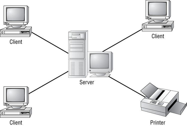
Server-based networks are also known as domains. The key characteristic of a domain is that security is centrally administered. When you log in to the network, the login request is passed to the server responsible for security, sometimes known as a domain controller. (Microsoft uses the term domain controller, whereas other vendors of server products do not.) This is different from the peer-to-peer model, where each individual workstation validates users. In a peer-to-peer model, if the user jsmith wants to be able to log in to different workstations, she needs to have a user account set up on each machine. This can quickly become an administrative nightmare! In a domain, all user accounts are stored on the server. User jsmith needs only one account and can log on to any of the workstations in the domain.
Client-server resource models are the desired models for companies that are continually growing, need to support a large environment, or need centralized security. Server-based networks offer the flexibility to add more resources and clients almost indefinitely into the future. Hardware costs may be more, but with the centralized administration, managing resources becomes less time consuming. Also, only a few administrators need to be trained, and users are responsible for only their own work environment.
Whatever you decide, always take the time to plan your network before installing it. A network is not something you can just throw together. You don’t want to find out a few months down the road that the type of network you chose does not meet the needs of the company—this could be a time-consuming and costly mistake.
Network Topologies
A topology is a way of laying out the network. When you plan and install a network, you need to choose the right topology for your situation. Each type differs by its cost, ease of installation, fault tolerance (how the topology handles problems such as cable breaks), and ease of reconfiguration (such as adding a new workstation to the existing network).
There are five primary topologies:
- Bus
- Star
- Ring
- Mesh
- Hybrid
Each topology has advantages and disadvantages. After the following sections, check out Table 6-1, which summarizes the advantages and disadvantages of each topology.
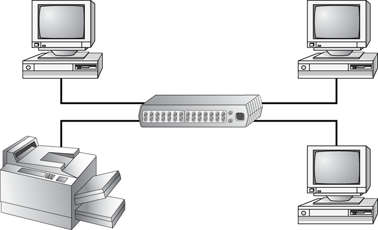
Bus Topology
A bus topology is the simplest. It consists of a single cable that runs to every workstation, as shown in Figure 6-7. This topology uses the least amount of cabling. Each computer shares the same data and address path. With a bus topology, messages pass through the trunk, and each workstation checks to see if a message is addressed to itself. If the address of the message matches the workstation’s address, the network adapter retrieves it. If not, the message is ignored.
Figure 6-7: The bus topology
Cable systems that use the bus topology are easy to install. You run a cable from the first computer to the last computer. All the remaining computers attach to the cable somewhere in between. Because of the simplicity of installation, and because of the low cost of the cable, bus topology cabling systems are the cheapest to install.
Although the bus topology uses the least amount of cabling, it is difficult to add a workstation. If you want to add another workstation, you have to completely reroute the cable and possibly run two additional lengths of it. Also, if any one of the cables breaks, the entire network is disrupted. Therefore, such a system is expensive to maintain and can be difficult to troubleshoot. You will rarely run across physical bus networks in use today.
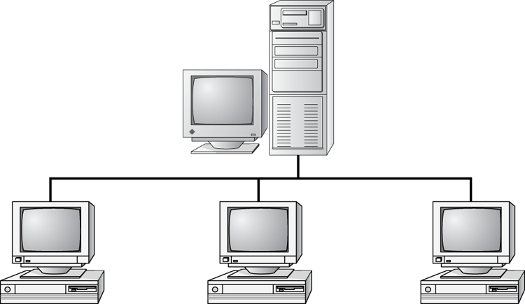
Star Topology
A star topology branches each network device off a central device called a hub, making it easy to add a new workstation. If a workstation goes down, it does not affect the entire network; if the central device goes down, the entire network goes with it. Because of this, the hub (or switch) is called a single point of failure. Figure 6-8 shows a simple star network.
Star topologies are very easy to install. A cable is run from each workstation to the hub. The hub is placed in a central location in the office (for example, a utility closet). Star topologies are more expensive to install than bus networks because several more cables need to be installed, plus the hubs. But the ease of reconfiguration and fault tolerance (one cable failing does not bring down the entire network) far outweigh the drawbacks. This is the most commonly installed network topology in use today.
Figure 6-8: The star topology
Ring Topology
In a ring topology, each computer connects to two other computers, joining them in a circle and creating a unidirectional path where messages move from workstation to workstation. Each entity participating in the ring reads a message and then regenerates it and hands it to its neighbor on a different network cable. See Figure 6-9 for an example of a ring topology.
Figure 6-9: The ring topology
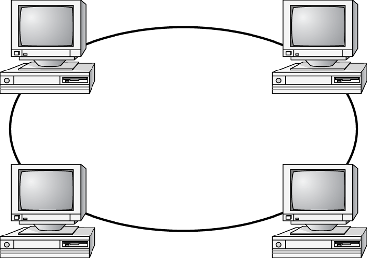
The ring makes it difficult to add new computers. Unlike a star topology network, the ring topology network will go down if one entity is removed from the ring. Physical ring topology systems rarely exist anymore, mainly because the hardware involved was fairly expensive and the fault tolerance was very low.
Mesh Topology
The mesh topology is the most complex in terms of physical design. In this topology, each device is connected to every other device (Figure 6-10). This topology is rarely found in LANs, mainly because of the complexity of the cabling. If there are x computers, there will be (x × (x – 1)) ÷ 2 cables in the network. For example, if you have five computers in a mesh network, it will use 5 × (5 – 1) ÷ 2 = 10 cables. This complexity is compounded when you add another workstation. For example, your 5-computer, 10-cable network will jump to 15 cables if you add just one more computer. Imagine how the person doing the cabling would feel if you told them they had to cable 50 computers in a mesh network—they’d have to come up with 50 × (50 – 1) ÷ 2 = 1225 cables!
Figure 6-10: The mesh topology
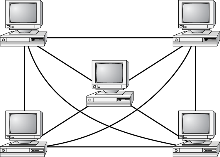
Because of its design, the physical mesh topology is expensive to install and maintain. Cables must be run from each device to every other device. The advantage you gain is high fault tolerance. With a mesh topology, there will always be a way to get the data from source to destination. The data may not be able to take the direct route, but it can take an alternate, indirect route. For this reason, the mesh topology is found in WANs to connect multiple sites across WAN links. It uses devices called routers to search multiple routes through the mesh and determine the best path. However, the mesh topology does become inefficient with five or more entities because of the number of connections that need to be maintained.
Hybrid Topology
The hybrid topology is simply a mix of the other topologies. It would be impossible to illustrate it because there are many combinations. In fact, most networks today are not only hybrid but heterogeneous (they include a mix of components of different types and brands). The hybrid network may be more expensive than some types of network topologies, but it takes the best features of all the other topologies and exploits them.
Table 6-1 summarizes the advantages and disadvantages of each type of network topology.
Table 6-1: Topologies—advantages and disadvantages
| Topology | Advantages | Disadvantages |
| Bus | Cheap. Easy to install. | Difficult to reconfigure. A break in the bus disables the entire network. |
| Star | Cheap. Very easy to install and reconfigure. Fault tolerant. | More expensive than bus. |
| Ring | Efficient. Easy to install. | Reconfiguration is difficult. Very expensive. |
| Mesh | Best fault tolerance. | Reconfiguration is extremely difficult, extremely expensive, and very complex. |
| Hybrid | Gives a combination of the best features of each topology used. | Complex (less so than mesh, however). |
Rules of Communication
Regardless of the type of network you choose to implement, the computers on that network need to know how to talk to each other. To facilitate communication across a network, computers use a common language called a protocol. We’ll cover protocols more in Chapter 7, “Introduction to TCP/IP,” but essentially they are languages much like English is a language. Within each language, there are rules that need to be followed so that both computers understand the right communication behavior.
To use a human example, within English there are grammar rules. If you put a bunch of English words together in a way that doesn’t make sense, no one will understand you. If you just decide to omit verbs from your language, you’re going to be challenged to get your point across. And if everyone talks at the same time, the conversation can be hard to follow.
Computers need standards to follow to keep their communication clear. Different standards are used to describe the rules that computers need to follow to communicate with each other. The most important communication framework, and the backbone of all networking, is the OSI model.
OSI Model
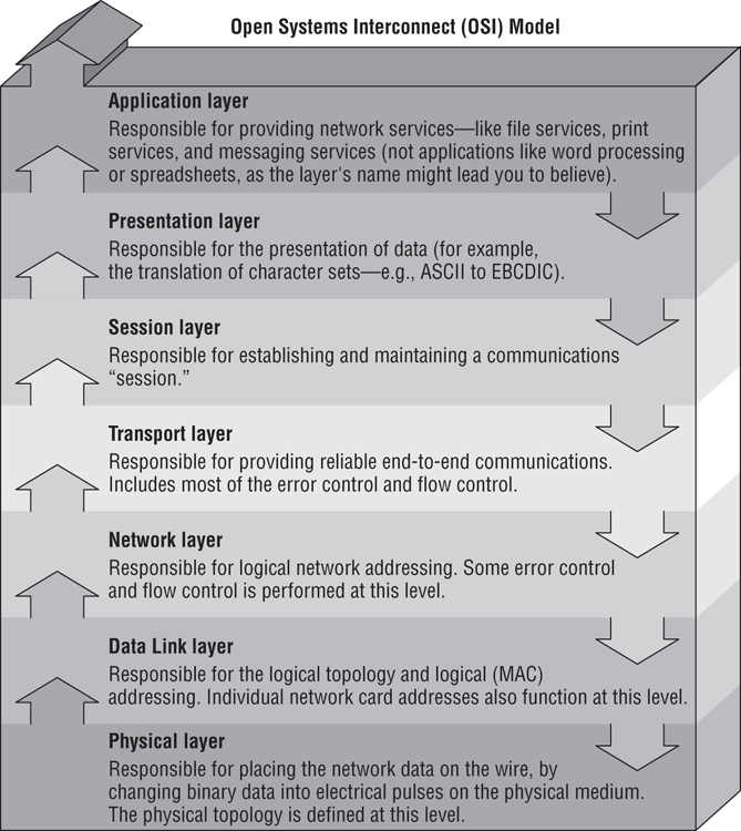
The International Organization for Standardization (ISO) introduced the Open Systems Interconnection (OSI) model to provide a common way of describing network protocols. The ISO put together a seven-layer model providing a relationship between the stages of communication, with each layer adding to the layer above or below it.
Here’s how the theory behind the OSI model works: As a transmission takes place, the higher layers pass data through the lower layers. As the data passes through a layer, that layer tacks its information (also called a header) onto the beginning of the information being transmitted until it reaches the bottom layer. A layer may also add a trailer to the end of the data. The bottom layer sends the information out on the wire.
At the receiving end, the bottom layer receives and reads the information in the header, removes the header and any associated trailer related to its layer, and then passes the remainder to the next highest layer. This procedure continues until the topmost layer receives the data that the sending computer sent.
The OSI model layers are listed here from top to bottom, as well as descriptions for what each of the layers is responsible for:
Figure 6-11 shows the complete OSI model. Note the relation of each layer to the others and the function of each layer.
IEEE 802 Standards
Continuing with our theme of communication, it’s time to introduce one final group of standards. You’ve already learned that a protocol is like a language; think of the IEEE 802 standards as syntax, or the rules that govern who communicates when and how.
The Institute of Electrical and Electronics Engineers (IEEE) formed a subcommittee to create standards for network types. These standards specify certain types of networks, although not every network protocol is covered by the IEEE 802 committee specifications. This model contains several categories, but the following are the most popularly referenced:
- 802.2 Logical Link Control
- 802.3 CSMA/CD (Ethernet) LAN
- 802.5 Token Ring LAN
- 802.6 Metropolitan Area Network
- 802.11 Wireless Networks
Figure 6-11: The OSI model
The IEEE 802 standards were designed primarily for enhancements to the bottom three layers of the OSI model. The IEEE 802 standard breaks the Data Link layer into two sublayers: a Logical Link Control (LLC) sublayer and a Media Access Control (MAC) sublayer. In the Logical Link Control sublayer, data link communications are managed. The Media Access Control sublayer watches out for data collisions and manages physical (MAC) addresses.
You’ve most likely heard of 802.11g wireless networking. The rules for communicating with all versions of 802.11 are defined by the IEEE standard. Another very well-known standard is 802.3 CSMA/CD. You might know it by its more popular name, Ethernet.
The original 802.3 CSMA/CD standard defines a bus topology network that uses a 50 ohm coaxial baseband cable and carries transmissions at 10Mbps. This standard groups data bits into frames and uses the Carrier Sense Multiple Access with Collision Detection (CSMA/CD) cable access method to put data on the cable. Currently, the 802.3 standard has been amended to include speeds up to 10Gbps.
Breaking the CSMA/CD acronym apart may help illustrate how it works. First, there is the Carrier Sense (CS) part, which means that computers on the network are listening to the wire at all times. Multiple Access (MA) means that multiple computers have access to the line at the same time. This is analogous to having five people on a conference call. Everyone is listening, and everyone in theory can try to talk at the same time. Of course, when more than one person talks at once, there is a communication error. In CSMA/CD, when two machines transmit at the same time, a data collision takes place and none of the data is received by the intended recipients. This is where the Collision Detection (CD) portion of the acronym comes in; the collision is detected and each sender knows they need to send again. Each sender then waits for a short random period of time and tries to transmit again. This process repeats until transmission takes place successfully. The CSMA/CD technology is considered a contention-based access method.
The only major downside to 802.3 is that with large networks (more than 100 computers on the same cable), the number of collisions increases to the point where more collisions than transmissions are taking place.
Other examples exist, such as 802.5 token ring, which defines a logical ring on a physical star. On a token ring network, an access packet called a token circles the network. If you have the token, you can send data; otherwise you wait for your turn. It’s not important to memorize all of the different IEEE standards for the test. Just know that different ones exist, governing how to transmit data on the wire and making sure all computers co-exist peacefully.