
Identifying Purposes and Characteristics of Power Supplies
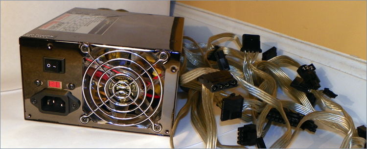
The computer’s components would not be able to operate without power. The device in the computer that provides this power is the power supply (Figure 2-24). A power supply converts 110V or 220V AC current into the DC voltages that a computer needs to operate. These are +3.3VDC, +5VDC, –5VDC (on older systems), +12VDC, and –12VDC. The jacket on the leads carrying each type of voltage has a different industry-standard color coding for faster recognition. Black ground leads offer the reference that gives the voltage leads their respective magnitudes. The +3.3VDC voltage was first offered on ATX motherboards.
Figure 2-24: A power supply
Power supplies are rated in watts. A watt is a unit of power. The higher the number, the more power your computer can draw from the power supply. Think of this rating as the “capacity” of the device to supply power. Most computers require power supplies in the 250- to 500-watt range. Higher wattage power supplies might be required for more advanced systems that employ power-hungry graphics technologies or multiple disk drives, for instance. It is important to consider the draw that the various components and subcomponents of your computer place on the power supply before choosing one or its replacement.
Classic power supplies used only three types of connectors to power the various devices within the computer: floppy drive power connectors, AT system connectors, and standard peripheral power connectors. Each has a different appearance and way of connecting to the device. In addition, each type is used for a specific purpose. Newer systems have a variety of similar, replacement, and additional connectors, such as dedicated power connectors for SATA and PCIe, additional power connectors for the motherboard, and even modular connections for these leads back to the power supply instead of a permanent wiring harness.
Most power supplies have a recessed, two-position slider switch, often a red one, on the rear that is exposed through the case. You can see the one for the power supply in Figure 2-24. Selections read 110 and 220, 115 and 230, or 120 and 240. This dual voltage selector switch is used to adjust for the voltage level used in the country where the computer is in service. For example, in the United States, the power grid supplies anywhere from 110 to 120VAC. However, in Europe, for instance, the voltage supplied is double, ranging from 220 to 240VAC.
Although the voltage is the same as what is used in the United States to power high-voltage appliances, such as electric ranges and clothes driers, the amperage is much lower. The point is, the switch is not there to match the type of outlet used in the same country. If the wrong voltage is chosen in the United States, the power supply expects more voltage than it receives and might not power up at all. If the wrong voltage is selected in Europe, however, the power supply receives more voltage than it is set for. The result could be disastrous for the entire computer. Sparks could also ignite a fire that could destroy nearby property and endanger lives. Always check the switch before powering up a new or recently relocated computer. In the United States and other countries that use the same voltage, check the setting of this switch if the computer fails to power up.
Power Connectors
The connectors coming from the power supply are quite varied these days, but there are also some connectors that are considered legacy connectors that you might not see on modern power supplies. The following sections detail and illustrate the most common of these connectors.
Classic Power Connectors
The classic connectors comprise outdated connectors as well as connectors still in use today despite being found in the original IBM PC.
AT System Connector
The original power connectors attached to the early PC motherboards were known collectively as the AT system connector. There are two six-wire connectors, labeled P8 and P9 (as shown in Figure 2-25). They connect to an AT-style motherboard and deliver the power that feeds the electronic components on it. These connectors have small tabs on them that interlock with tabs on the motherboard’s receptacle.
Figure 2-25: AT power supply system board connectors
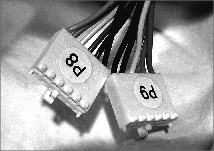
The P8 and P9 connectors must be installed correctly or you will damage the motherboard and possibly other components. To do this (on standard systems), place the connectors side by side with their black wires together, and then push the connectors together or separately onto the 12-pin receptacle on the motherboard. Although there is keying on these connectors, they both use the exact same keying structure. In other words, they can still be swapped with one another and inserted. When the black ground leads are placed together when the connectors are side by side, it is not possible to flip the pair 180 degrees and still insert the two connectors without physically defeating the keying. Most technicians would give up and figure out their mistake before any damage occurs if they always place the grounds together in the middle.

It is important to note that only legacy computers with AT and baby AT motherboards use this type of power connector.
Standard Peripheral Power Connector
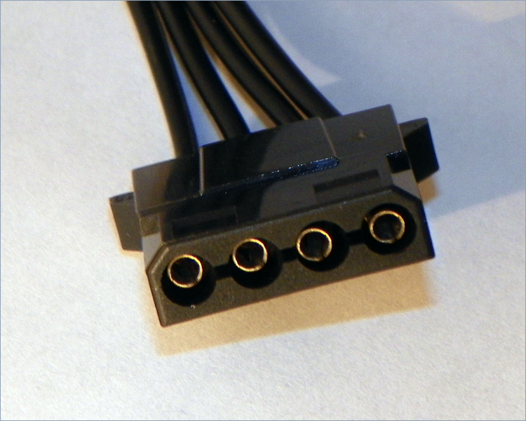
The standard peripheral power connector is generally used to power different types of internal disk drives. This type of connector is also called a Molex connector. Figure 2-26 shows an example of a standard peripheral power connector. This power connector, though larger than the floppy drive power connector, uses the same wiring color code scheme as the floppy drive connector, although with a heavier gauge of wire. The added copper is for the additional current drawn by most devices that call for the Molex interface.
Figure 2-26: A standard peripheral power connector
Floppy Drive Power Connectors
Floppy drive power connectors are most commonly used to power floppy disk drives and other small form factor devices. This type of connector is smaller and flatter (as shown in Figure 2-27) than any of the other types of power connectors. These connectors are also called Berg connectors. Notice that there are four wires going into this connector. These wires carry the two voltages used by the logic circuits and motors: +5VDC (carried on the red wire) and +12VDC (carried on the yellow wire), respectively; the two black wires are ground wires.
Figure 2-27: Floppy drive power connector
Modern Power Connectors
Modern components have exceeded the capabilities of some of the original power supply connectors. The Molex and Berg peripheral connectors remain, but the P8/P9 motherboard connectors have been consolidated and augmented, and additional connectors have sprung up.
ATX, ATX12V, and EPS12V Connectors
With ATX motherboards came a new, single connector from the power supply. PCI Express has power requirements that even this connector could not satisfy, leading to different connectors with different versions of the more advanced ATX12V specifications, which have gone through four 1.x versions and already five 2.x versions. Throughout the versions of ATX12V, additional 4-, 6-, and 8-pin connectors supply power to components of the motherboard and its peripherals—such as network interfaces, PCIe cards, specialty server components, and the CPU itself—that require a +12V supply in addition to the +12V of the standard ATX connector. These additional connectors follow the ATX12V and EPS12V standards. The ATX connector was further expanded by an additional four pins in ATX12V 2.0.
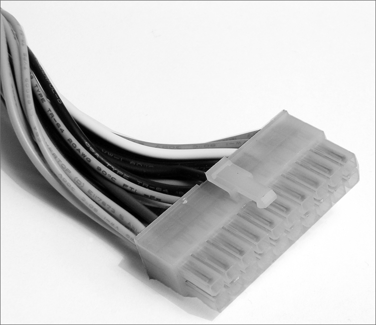
The original ATX system connector (also known as the ATX motherboard power connector) feeds an ATX motherboard. It provides the six voltages required, plus it delivers them all through one connector: a single 20-pin connector. This connector is much easier to work with than the dual connectors of the AT power supply. Figure 2-28 shows an example of an ATX system connector.
Figure 2-28: ATX power connector
When the Pentium 4 processor was introduced, it required much more power than previous CPU models. Power measured in watts is a multiplicative function of voltage and current. To keep the voltage low meant amperage would have to increase, but it wasn’t feasible to supply such current from the power supply itself. Instead, it was decided to deliver 12V at lower amperage to a voltage regulator module (VRM) near the CPU. The higher current at a lower voltage was possible at that shorter distance from the CPU.
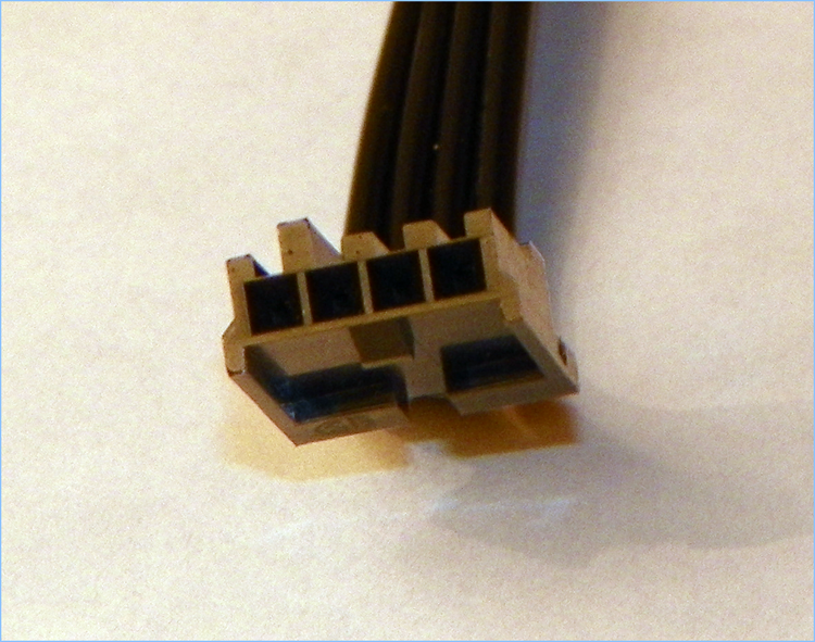
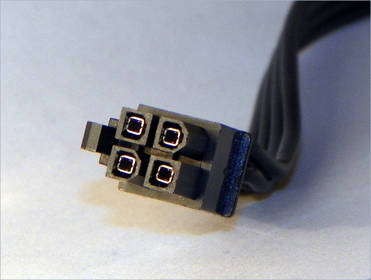
As a result of this shift, motherboard and power supply manufacturers needed to get this more varied power to the system board. The solution was the ATX12V 1.0 standard, which added two supplemental connectors. One was a single 6-pin auxiliary connector similar to the P8/P9 AT connectors that supplied additional +3.3V and +5V leads and their grounds. The other was a 4-pin square mini-version of the ATX connector, referred to as a P4 (for the processor that first required them) connector, that supplied two +12V leads and their grounds. EPS12V uses an 8-pin version, called the processor power connector, that doubles the P4’s function with four +12V leads and four grounds. Figure 2-29 illustrates the P4 connector. The 8-pin processor power connector is similar but has two rows of 4 and, despite its uncanny resemblance, is keyed differently from the 8-pin PCIe power connector to be discussed shortly.
Figure 2-29: ATX12V P4 power connector
For servers and more advanced ATX motherboards that include PCIe slots, the 20-pin system connector proved inadequate. This led to the ATX12V 2.0 standard and the even higher-end EPS12V standard for servers. These specifications call for a 24-pin connector that adds additional positive voltage leads directly to the system connector. The 24-pin connector looks like a larger version of the 20-pin connector. The corresponding pins of the 24-pin motherboard header are actually keyed to accept the 20-pin connector. Adapters are available if you find yourself with the wrong combination of motherboard and power supply. Many power supplies feature a 20-pin connector that snaps together with a separate 4-pin portion for flexibility, called a 20+4 connector, which can be seen in Figure 2-30. The 6-pin auxiliary connector disappeared with the ATX12V 2.0 specification and was never part of the EPS12V standard.
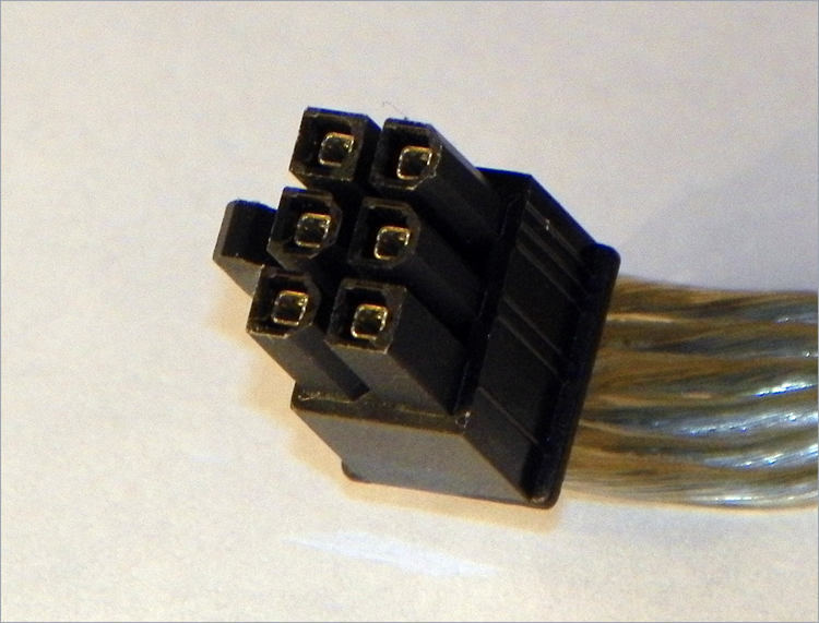
ATX12V 2.1 introduced a different 6-pin connector, which was shaped more like the P4 connector than the P8/P9-style auxiliary connector from the 1.x standards. See Figure 2-31. This 6-pin connector was specifically designed to give additional dedicated power to PCIe adapters that required it. It provided a 75W power source to such devices.
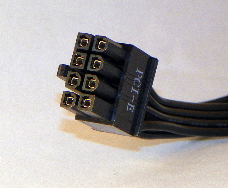
ATX12V 2.2 replaced the 75W 6-pin connector with a 150W 8-pin connector, shown in Figure 2-32. The plastic bridge between the top two pins on the left side in the photo keeps installers from inserting the connector into the EPS12V processor power header but clears the notched connector of a PCIe adapter. The individual pin keying should avoid this issue, but a heavy-handed installer could defeat that. The bridge also keeps the connector from inserting into a 6-pin PCIe header, which has identically keyed corresponding pins.
Figure 2-30: A 24-pin ATX12V 2.x connector in two parts
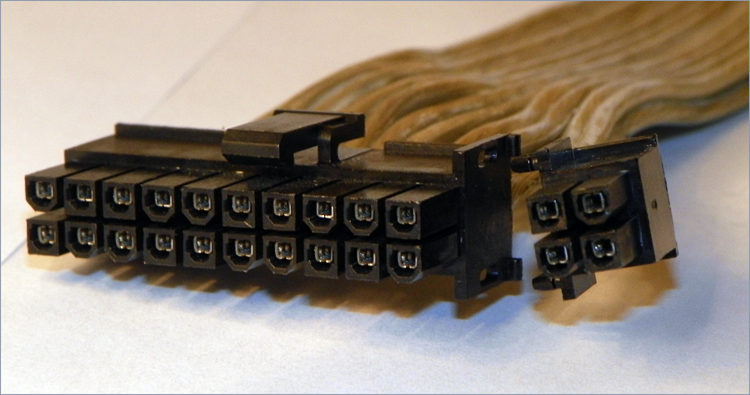
Figure 2-31: A 6-pin ATX12V 2.1 PCIe connector
Proprietary Power Connectors
Although the internal peripheral devices have standard power connectors, manufacturers of computer systems sometimes take liberties with the power interface between the motherboard and power supply of their systems. In some cases, the same voltages required by a standard ATX power connector are supplied using one or more proprietary connectors. This makes it virtually impossible to replace power supplies and motherboards with other units “off the shelf.” Manufacturers might do this to solve a design issue or simply to ensure repeat business.
Figure 2-32: An 8-pin ATX12V 2.2 PCIe connector
SATA Power Connectors
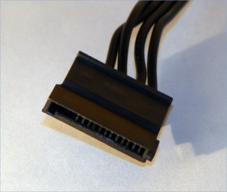
SATA drives arrived on the market with their own power requirements in addition to their new data interfaces. Refer back to Figure 2-11 and imagine a larger but similar connector for power. You get the 15-pin SATA power connector, a variant of which is shown in Figure 2-33. The fully pinned connector is made up of three +3.3V, three +5V, and three +12V leads interleaved with two sets of three ground leads. Each of the five sets of three common pins is supplied by one of five single conductors coming from the power supply. The same colors are generally used for the conductors as with the Molex and Berg connectors. When the optional 3.3V lead is supplied, it is standard to see it delivered on an orange conductor.
Note that in Figure 2-33, the first three pins are missing. These correspond to the 3.3V pins, which are not supplied by this connector. This configuration works fine and alludes to SATA drives’ ability to accept Molex connectors or adapters attached to Molex connectors, thus working without the optional 3.3V lead.
Figure 2-33: SATA power connector
Replacing Power Supplies
Sometimes power supplies fail. Sometimes you grow out of your power supply and require more wattage than it can provide. Often, it is just as cost effective to buy a whole new case with the power supply included rather than dealing with the power supply alone. However, when you consider the fact that you must move everything from the old case to the new one, replacing the power supply becomes an attractive proposition. Doing so is not a difficult task.
Regardless of which path you choose, you must make sure the power connection of the power supply matches that of the motherboard to be used. Years ago, a new power supply with the single 20-pin ATX power connector wouldn’t do a thing for you if you had a motherboard that had only the older P8/P9 connectors, although there are adapters that allow interconnection. Recall that the 24-pin ATXV2 2.x power supply connection can also be adapted to a motherboard with the 20-pin ATX connector.
Additionally, the physical size of the power supply should factor into your purchasing decision. If you buy a standard ATX-compatible power supply, it might not fit in the petite case you matched up to your micro-ATX motherboard. In that scenario, you should be on the lookout for a smaller form factor power supply to fit the smaller case. Odds are the offerings you find out there will tend to be a little lighter in the wattage department as well.
Exercise 2.3 details the process to remove an existing power supply. Use the reverse of this process to install the new power supply. Just keep in mind that you might need to procure the appropriate adapter if a power supply that matches your motherboard can no longer be found. There is no postinstallation configuration for the power supply, so there is nothing to cover along those lines. Many power supply manufacturers have utilities on their websites that allow you to perform a presale configuration so that you are assured of obtaining the most appropriate power supply for your power requirements.
AC Adapters as Power Supplies
Just as the power supply in a desktop computer converts AC voltages to DC for the internal components to run on, the AC adapter of a laptop computer converts AC voltages to DC for the laptop’s internal components. And AC adapters are rated in watts and selected for use with a specific voltage just as power supplies are. One difference is that AC adapters are also rated in terms of DC volts out to the laptop or other device, such as certain brands and models of printer.
Because both power supplies and AC adapters go bad on occasion, you should replace them both and not attempt to repair them yourself. When replacing an AC adapter, be sure to match the size, shape, and polarity of the tip with the adapter you are replacing. However, because the output DC voltage is specified for the AC adapter, be sure to replace it with one of equal output voltage, an issue not seen when replacing AT or ATX power supplies, which have standard outputs. Additionally, and as with power supplies, you can replace an AC adapter with a model that supplies more watts to the component because the component uses only what it needs.
You can read more on this subject later in Chapter 9, “Understanding Laptops.”