
Disassembling and Reassembling Laptops
Desktop computers often have a lot of empty space inside their cases. This lets air circulate and also gives the technician some room to maneuver when troubleshooting internal hardware. Space is at a premium in laptops, and rarely is any wasted. With a desktop computer, if you end up having an extra screw left over after putting it together, it’s probably not a big deal. With laptops, every screw matters, and you’ll sometimes find yourself trying to visually identify miniscule differences between screws to make sure you get them back into the right places.
Even though repairing a laptop poses unique issues, most of the general troubleshooting and safety tips you use when troubleshooting a desktop still apply. For example, always make sure you have a clean and well-lit work space and be cautious of electrostatic discharge (ESD). General safety tips and ESD prevention is covered in Chapter 11, “Understanding Operational Procedures.” Here, we’ll get in to specific objectives for tearing apart laptops.
Using the Right Tools
It’s doubtful that any technician goes into a job thinking, “Hey, I’m going to use the wrong tools just to see what happens.” With laptops, though, it’s especially important to ensure that you have exactly the tools you need for the job. Two critical camps of materials you need are the manufacturer’s documentation and the right hand tools.
Using the Manufacturer’s Documentation
Most technicians won’t bat an eye at whipping out their cordless screwdriver and getting into a desktop’s case. The biggest difference between most desktops is how you get inside the case. Once it’s opened, everything inside is pretty standard fare.
Laptops are a different story. Even experienced technicians will tell you to not remove a single screw until you have the documentation handy unless you’re incredibly familiar with that particular laptop. Most laptop manufacturers give you access to repair manuals on their website; Table 9-2 lists the service and support websites for some of the top laptop manufacturers.
Table 9-2: Laptop manufacturers’ service and support websites


Once you are at the right website, search for the manual using the laptop’s model number.
Using the Right Hand Tools
Once you have the manual in hand or on your screen, you need to gather the right hand tools for the job. For some laptops, you only need the basics, such as small Phillips-head and straight-edge screwdrivers. For others, you may need a Torx driver. Gather the tools you need and prepare to open the case. A small flashlight might also come in handy.
Organization and Documentation
Before you crack the case of your laptop, have an organization and documentation plan in place. Know where you are going to put the parts. Have a container set aside for the screws. You can purchase small plastic containers that have several compartments in them with lids that snap tightly shut, to place screws in. You can also use containers designed to organize prescription pills. The bottom of an egg carton works well too, provided you don’t need to be mobile to fix the laptop.
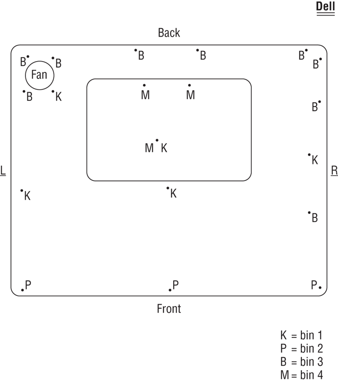
For documentation, many technicians find it handy to draw a map of the computer they’re getting into, such as the one shown in Figure 9-22. It can be as complex as you want it to be, as long as it makes sense to you.
The drawing in Figure 9-22 shows the locations of the screws, and also calls out where the screws should be placed once they’re removed. Again, this type of documentation can be as simple or complex as you want it to be, as long as it makes sense and helps you stay organized.
Replacing Laptop Components
You have your manual, screwdrivers, and screw container handy and are ready to go. Now you just need to figure out how to get to the defective component to replace it. It would be nice if we could just tell you one simple way to do this for all laptops, but that’s not going to happen. Internal laptop structure, components that can be replaced, and how to get to those components varies widely between models. It’s impractical to list steps to remove all of these devices because the steps we would list here will only help you if you’re working on the same model of laptop we’re using for an example.
Figure 9-22: Laptop repair “road map”
The list of components that may be replaceable could include input devices such as the keyboard and Touchpad; storage devices, including hard drives and optical drives; core components such as memory, the processor, and the motherboard; expansion options, including wireless cards and mini-PCIe cards; and integrated components such as the screen, plastics, speakers, battery, and DC jack. Again, depending on the make and model of the laptop you’re working on, the list of replaceable components might be longer or shorter.
In the following sections, we’re going to assume you’ve figured out what’s defective and needs to be replaced. We’ll stay away from describing components and what they do, unless it’s not been covered elsewhere in the book. The model we’re going to use in the examples in the rest of this chapter is a Dell Latitude C640. Admittedly, this particular model is a bit dated, but all of the procedures we’re going to walk you through will still be similar for newer systems. For other models, please consult the manufacturer’s documentation.
Replacing Hard Drives and Memory
Hard drives and memory are the two most common components people usually upgrade in a laptop. We’ll look at how to accomplish replacing both of them.
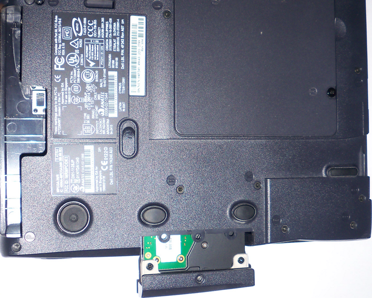
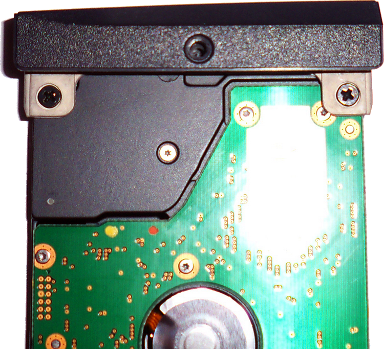
Replacing Hard Drives
External storage devices are more popular now than they ever have been. On the small end, you can get postage-stamp-sized SD memory sticks or ultra-portable thumb drives that hold a few gigabytes each. If you need more storage, you can get external hard drives that hold in excess of one terabyte and connect to your laptop using a USB cable.
Even with all of those options, a laptop still needs an internal hard drive. Exercise 9.1 shows you how to remove and replace an internal hard drive.
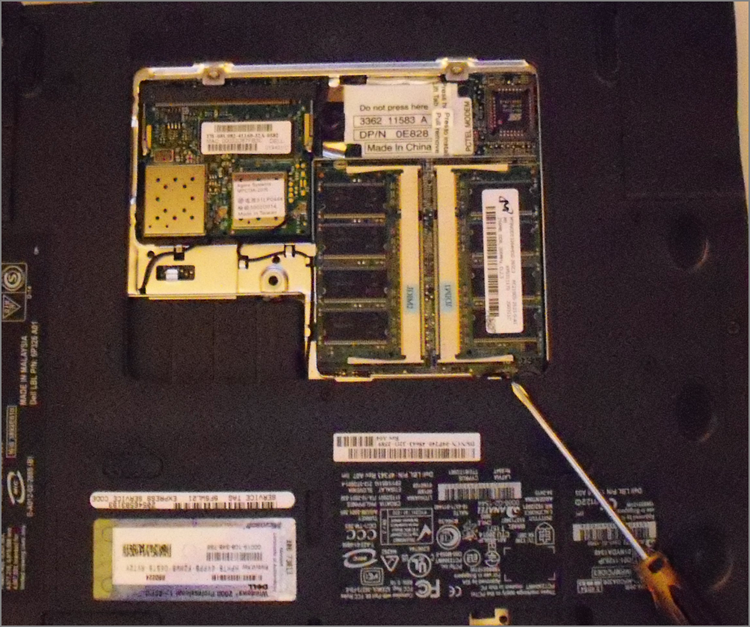
Replacing Memory
No matter how much memory your laptop has, it’s probably not enough. Most laptops share their system memory with the video card, meaning that memory on a laptop might not go as far as you think.
Not long ago there weren’t any standards for the physical size of laptop memory. Manufacturers weren’t in a hurry to conform to each other either. After all, if they were the only ones producing memory for their systems, then they could pretty much charge what they wanted.
Fortunately, standards do exist today, and most manufacturers will use memory that conforms to SODIMM (or MicroDIMM) standards. Only occasionally will you run into a laptop that uses proprietary memory modules. Your documentation will tell you what type of memory your system takes. Exercise 9.2 shows you how to access the memory bay so you can upgrade or replace memory chips.
Replacing Internal Laptop Expansion Cards
As we covered earlier in the chapter, laptops have their own proprietary architecture for internal expansion. The two most common standards are Mini PCI and Mini PCIe, and they’re covered in detail in the section “Expansion Buses and Ports” earlier in this chapter.
Most laptops will come with only one Mini PCI or Mini PCIe port, and common Mini PCI devices include SCSI controllers, SATA controllers, network cards, sound cards, and modems. Refer back to Table 9-1 for the dimensions of the various Mini PCI form factors.
Figure 9-23 shows you the Type IIIA Mini PCI network card installed in this laptop, which happens to be in the same bay as the system memory. The connector is on the top side of the figure.
Figure 9-23: Mini PCI card installed in a laptop
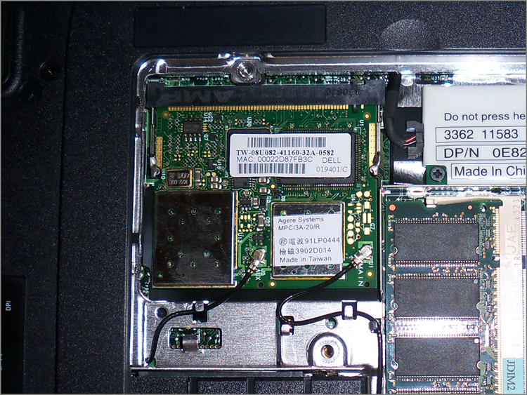
Removing the Mini PCI card is just like removing the memory, except that this one has antenna cables you need to disconnect first. After that, spread the retaining clips just as you would for the memory and the card will pop up. Replace it with a new card the same way you would replace a memory module.
Mini PCIe cards have a 52-pin card edge connector, and removing and replacing them is similar to removing and replacing Mini PCI cards.
Upgrading Wireless and Video Systems
What do wireless network cards and video cards have in common in laptops? Most of the time, they’re integrated into your system motherboard. If either one fails, you need to replace the entire motherboard. A few laptops have these components as separate field-replaceable units (FRUs), and you can remove them as needed. The only way to know for sure is to consult your trusty service manual. The following sections look at some ways you may be able to upgrade these devices.
Upgrading Wireless Network Cards
Wireless network cards and laptops are a perfect match for each other, much like peanut butter and chocolate. You can have one without the other, but what’s the point, really?
Most network cards are built into the motherboard chipset of laptops. In other words, if it fails, you likely need to replace the motherboard. Network cards are special, though, in that you have many other easier ways to upgrade if you want to.
On the market you can find several external portable network cards. You often have choices that range from network cards that look like a thumb drive and have a USB connector to slightly bulkier PC Card network cards. These are even valid options if your built-in network card is still working but you want to upgrade. For example, if you have an older laptop with an 802.11b network card in it but you want to upgrade to 802.11g or 802.11n, it may be more economical to purchase an external card and use it in your system. Windows should disable the old device automatically to avoid conflicts, but if not, you can do it manually through Device Manager.
Upgrading Laptop Video Cards
Odds are that the laptop you’re working on has an integrated video card. If the video card fails, you’re likely looking at a motherboard replacement. Some laptops do have a replaceable video card. If it fails or if you choose to upgrade it, the procedure will probably resemble replacing system memory. The Dell Latitude C640 we’ve been using as an example has a built-in video card, so there’s no way to upgrade that specific device. For an example of what it might take to replace a video card, we’ll use a Dell Inspiron 6000 in Exercise 9.3.
Replacing LCD Components
Besides the video card, many of the LCD components (the screen, backlight, and inverter) in a laptop can be replaced. Replacing these components often means removing the LCD display from the main chassis of the laptop. When doing so, just be careful of the video circuitry that connects the two, and the wireless network card antenna wires, which are usually threaded through one of the laptop case hinges.
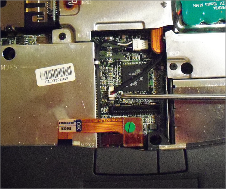
Replacing Other Internal Components
By now you have probably gotten the idea that in order to know how to replace components inside your laptop, you need to check the laptop’s manual. The upshot is that nearly every component you can think of replacing in a desktop computer is also replaceable in a laptop. It just might require a bit more work to fix the laptop than it would to fix a desktop.
As a rule of thumb, you can either access components from the bottom of your laptop, such as the memory, Mini PCI card, and modem in the Latitude C640, or you’re going to need to remove the keyboard to access the components from the top.
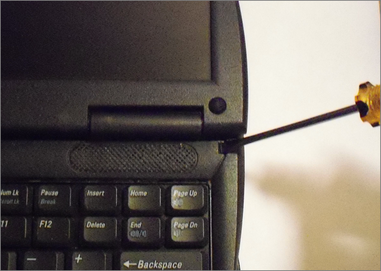
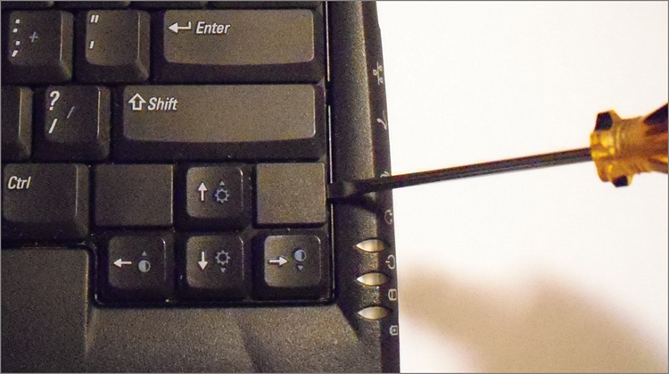
As the keyboard is often the gateway to the guts of a laptop, we will include an example of removing it. We’ll also include a few other examples of components you may need to replace in your line of work. Exercise 9.4 shows you how to remove a keyboard.
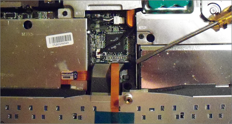
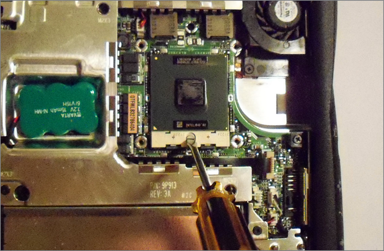
Now that the keyboard is off, you can remove several other components with relative ease. Exercise 9.5 looks at removing the processor cooling assembly and the processor.
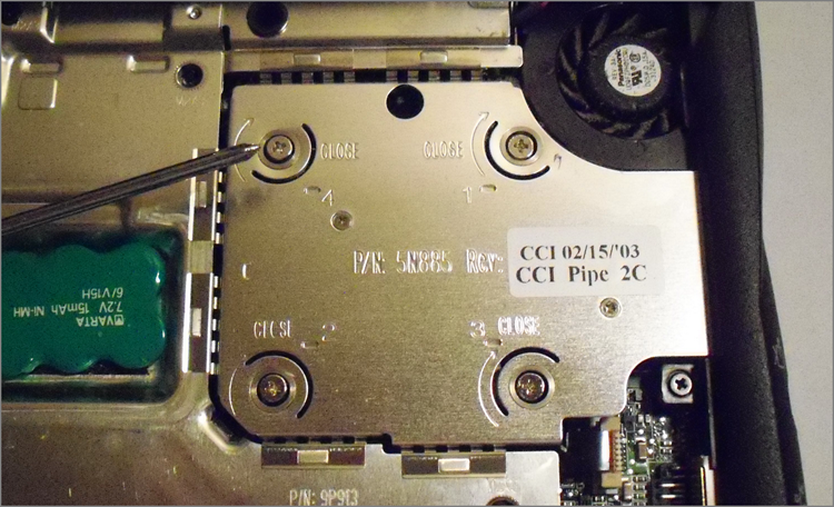
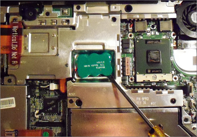
The last internal device we’ll look at removing is the CMOS battery. If the BIOS isn’t maintaining system information such as the date and time or boot sequence, you will want to replace this component. Exercise 9.6 shows you how to replace the CMOS battery.
Flashing the system BIOS is usually a pretty straightforward process. You can get a BIOS update from the manufacturer and burn it to a CD. Once you have the CD, you just need to boot the laptop from the CD, and the disc will automatically flash the BIOS. Exercise 9.7 shows you the steps to flash the BIOS on this model.
Removing External Hardware
In the grand scheme of things, there are two types of peripherals: internal and external. We’ve already discussed removing internal hardware, and compared to that, removing external components is very easy. If you have USB-type devices plugged in, removing them is as easy as disconnecting them, but other peripherals require a bit more work.
Devices that can be removed when the computer is powered on are called hot-swappable devices. If you need to turn the computer off first, then the device is not hot swappable. There are several different hot-swappable peripherals, including mice, keyboards, some hard drives, network cards, printers, and others. Good examples of non-hot-swappable devices include motherboards and internal IDE hard drives. Odds are if it’s internal to your computer case, then it’s not hot swappable. Always be sure to check your hardware documentation to see if it’s safe to plug in or disconnect the device with the system powered on.
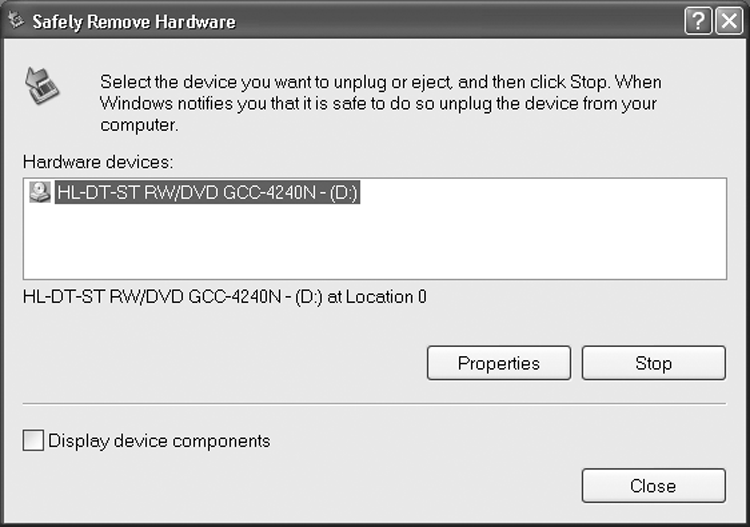
In Exercise 9.8, we will show you the recommended method to remove a device.

Adding an external device to a laptop generally means that the computer will automatically recognize and enable the device for you, unless there’s no compatible driver available. In cases like these, Windows will tell you that it detected new hardware and ask you to provide an appropriate driver.