
Understanding Printer Types and Processes
Several types of printers are available on the market today. As with all other computer components, there have been significant advancements in printer technology over the years. Most of the time when faced with the decision of purchasing a printer, you’re going to be weighing performance versus cost. Some of the higher-quality technologies, such as color laser printing, are rather expensive for the home user. Other technologies are less expensive but don’t provide the same level of quality.
In the following sections, you will learn about the various types of printers that you will see as a technician as well as their basic components and how they function. Specifically, we are going to look at four classifications of printers: impact, inkjet (bubble-jet), laser, and thermal.
Impact Printers
The most basic type of printer is in the category known as impact printers. Impact printers, as their name suggests, use some form of impact and an inked ribbon to make an imprint on the paper. Impact printers also use a paper feed mechanism called a tractor feed that requires special paper. Doubtless you’ve seen it before—it’s continuous feed paper with holes running down both edges. In a manner of speaking, typewriters are like impact printers. Both use an inked ribbon and an impact head to make letters on the paper. The major difference is that the printer can accept input from a computer.
There are two major types of impact printers: daisy wheel and dot matrix. Each type has its own service and maintenance issues.
Daisy-Wheel Printers
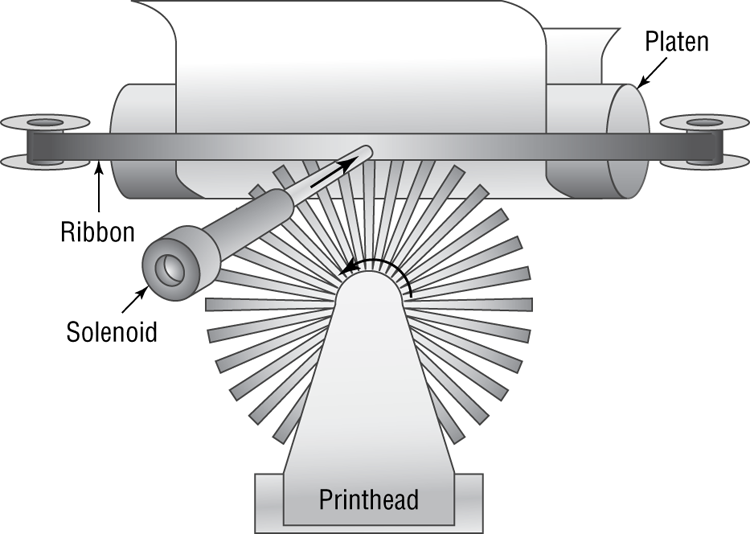
The first type of impact printer we’re going to discuss is the daisy-wheel printer. This is one of the oldest printing technologies in use. These impact printers contain a wheel (called the daisy wheel because it looks like a daisy) with raised letters and symbols on each “petal” (see Figure 10-1). When the printer needs to print a character, it sends a signal to the mechanism that contains the wheel. This mechanism is called the print head. The print head rotates the daisy wheel until the required character is in place. An electromechanical hammer (called a solenoid) then strikes the back of the petal containing the character. The character pushes up against an inked ribbon that ultimately strikes the paper, making the impression of the requested character.
Figure 10-1: A daisy-wheel printer mechanism
Daisy-wheel printers were among the first types of impact printer developed. Their speed is rated by the number of characters per second (cps) they can print. The earliest printers could print only two to four characters per second. Aside from their poor speed, the main disadvantage to this type of printer is that it makes a lot of noise when printing—so much, in fact, that special enclosures were developed to contain the noise.
The daisy-wheel printer has a few advantages, of course. First, because it is an impact printer, you can print on multipart forms (like carbonless receipts), assuming they can be fed into the printer properly. Sometimes you will hear this type of paper referred to as impact paper. Second, it is relatively inexpensive compared to the price of a laser printer of the same vintage. Finally, the print quality is comparable to that of a typewriter because it uses a very similar technology. This typewriter level of quality was given a name: letter quality (LQ). Today, LQ might refer to quality that’s better than a typewriter but not up to inkjet standards.
Dot-Matrix Printers
The other type of impact printer we’ll discuss is the dot-matrix printer. These printers work in a manner similar to daisy-wheel printers, but instead of a spinning, character-imprinted wheel, the print head contains a row of pins (short, sturdy stalks of hard wire). These pins are triggered in patterns that form letters and numbers as the print head moves across the paper (see Figure 10-2).
Figure 10-2: Formation of images in a dot-matrix printer
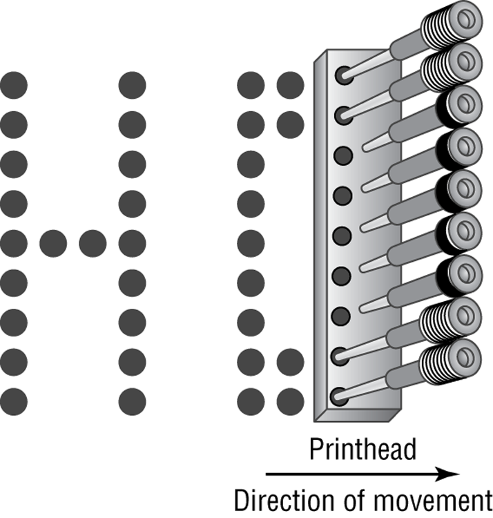
The pins in the print head are wrapped with coils of wire to create a solenoid and are held in the rest position by a combination of a small magnet and a spring. To trigger a particular pin, the printer controller sends a signal to the print head, which energizes the wires around the appropriate print wire. This turns the print wire into an electromagnet, which repels the print pin, forcing it against the ink ribbon and making a dot on the paper. The arrangement of the dots in columns and rows creates the letters and numbers you see on the page. Figure 10-2 shows this process.
The main disadvantage of dot-matrix printers is their image quality, which can be quite poor compared to the quality produced with a daisy wheel. Dot-matrix printers use patterns of dots to make letters and images, and the early dot-matrix printers used only nine pins to make those patterns. The output quality of such printers is referred to as draft quality—good mainly for providing your initial text to a correspondent or reviser. Each letter looked fuzzy because the dots were spaced as far as they could be and still be perceived as a letter or image. As more pins were crammed into the print head (17-pin and 24-pin models were eventually developed), the quality increased because the dots were closer together. Dot-matrix technology ultimately improved to the point that a letter printed on a dot-matrix printer was almost indistinguishable from typewriter output. This level of quality is known as near letter quality (NLQ).
Dot-matrix printers are noisy, but the print wires and print head are covered by a plastic dust cover, making them quieter than daisy-wheel printers. They also use a more efficient printing technology, so the print speed is faster (typically starting around 72cps). Some dot-matrix printers (like the Epson DFX series) can print at close to a page per second! Finally, because dot-matrix printers are also impact printers, they can use multipart forms. Because of these advantages, dot-matrix printers quickly made daisy-wheel printers obsolete.
Inkjet (Bubble-Jet)
One of the most popular types of printers in use today are inkjet printers. You might also hear these types of printers referred to as bubble-jet printers, but that term is copyrighted by Canon. As opposed to impact printers, which strike the page, these printers spray ink on the page to form the image. Older inkjet printers used a reservoir of ink, a pump, and a nozzle to accomplish this. They were messy, noisy, and inefficient. Bubble-jet printers work much more efficiently and are much cheaper. For purposes of the exam, consider them one in the same because their components and printing processes are nearly identical.
The main difference is that in a bubble-jet printer, droplets of ink are sprayed onto a page and form patterns that resemble the items being printed. You can think of it as spraying droplets of ink in a very high-definition dot-matrix pattern, although printer manufacturers would likely scoff at the comparison to an older technology. In the following sections, you will learn the parts of a bubble-jet printer as well as how bubble-jet printers work.
Parts of a Typical Bubble-Jet Printer
Bubble-jet printers are simple devices. They contain very few parts (even fewer than dot-matrix printers) and, as such, are inexpensive to manufacture. It’s common today to have a $40 to $50 bubble-jet printer with print quality that rivals that of basic laser printers.
The printer parts can be divided into the following categories:
- Print head/ink cartridge
- Head carriage, belt, and stepper motor
- Paper-feed mechanism
- Control, interface, and power circuitry
Print Head/Ink Cartridge
The first part of a bubble-jet printer is the one people see the most: the print head. This part of a printer contains many small nozzles (usually 100 to 200) that spray the ink in small droplets onto the page. Many times the print head is part of the ink cartridge, which contains a reservoir of ink and the print head in a removable package. Most color bubble-jet printers include multiple print heads, one for each of the CMYK (cyan, magenta, yellow, and black) print inks. The print cartridge must be replaced as the ink supply runs out.
Inside the ink cartridge are several small chambers. At the top of each chamber are a metal plate and a tube leading to the ink supply. At the bottom of each chamber is a small pinhole. These pinholes are used to spray ink on the page to form characters and images as patterns of dots, similar to the way a dot-matrix printer works but with much higher resolution.
There are two methods of spraying the ink out of the cartridge. The first was popularized by Hewlett-Packard (HP): When a particular chamber needs to spray ink, an electric signal is sent to the heating element, energizing it. The elements heat up quickly, causing the ink to vaporize. Because of the expanding ink vapor, the ink is pushed out the pinhole and forms a bubble. As the vapor expands, the bubble eventually gets large enough to break off into a droplet. The rest of the ink is pulled back into the chamber by the surface tension of the ink. When another drop needs to be sprayed, the process begins again. The second method, developed by Epson, uses a piezoelectric element (either a small rod or a unit that looks like a miniature drum head) that flexes when energized. The outward flex pushes the ink from the nozzle; on the return, it sucks more ink from the reservoir.
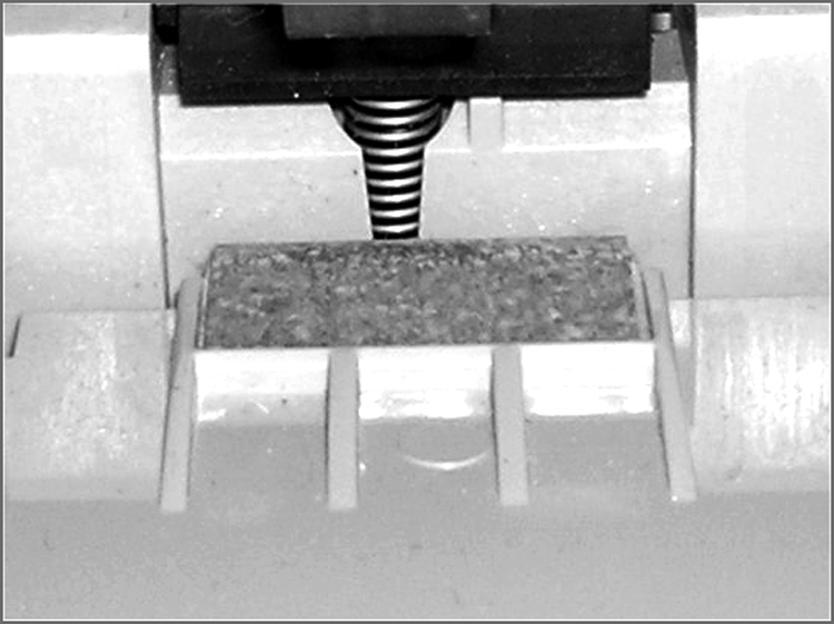
When the printer is done printing, the print head moves back to its maintenance station. The maintenance station contains a small suction pump and ink-absorbing pad. To keep the ink flowing freely, before each print cycle the maintenance station pulls ink through the ink nozzles using vacuum suction. This expelled ink is absorbed by the pad. The station serves two functions: to provide a place for the print head to rest when the printer isn’t printing and to keep the print head in working order.
Head Carriage, Belt, and Stepper Motor
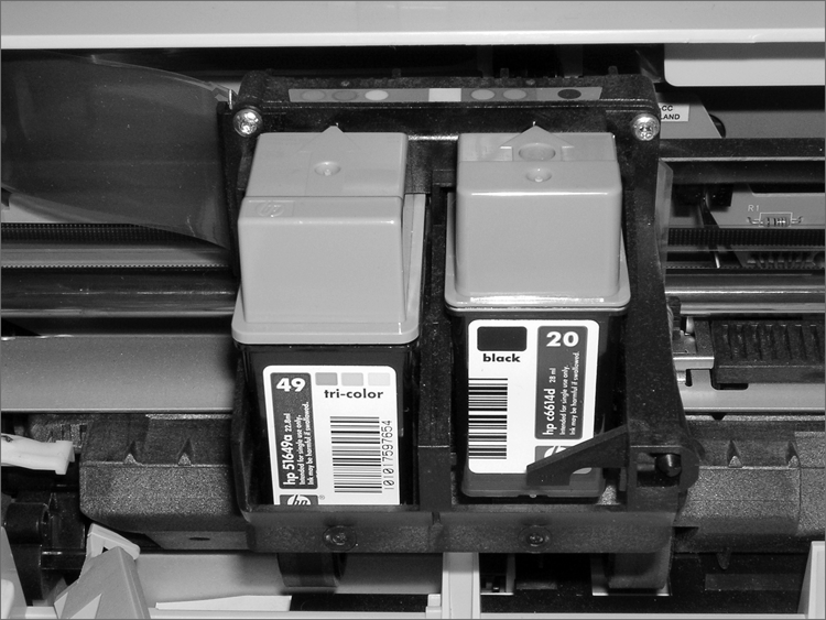
Another major component of the bubble-jet printer is the head carriage and the associated parts that make it move. The print head carriage is the component of a bubble-jet printer that moves back and forth during printing. It contains the physical as well as electronic connections for the print head and (in some cases) the ink reservoir. Figure 10-3 shows an example of a head carriage. Note the clips that keep the ink cartridge in place and the electronic connections for the ink cartridge. These connections cause the nozzles to fire, and if they aren’t kept clean, you may have printing problems.
Figure 10-3: A print head carriage (holding two ink cartridges) in a bubble-jet printer
The stepper motor and belt make the print head carriage move. A stepper motor is a precisely made electric motor that can move in the same very small increments each time it is activated. That way, it can move to the same position(s) time after time. The motor that makes the print head carriage move is also often called the carriage motor or carriage stepper motor. Figure 10-4 shows an example of a stepper motor.
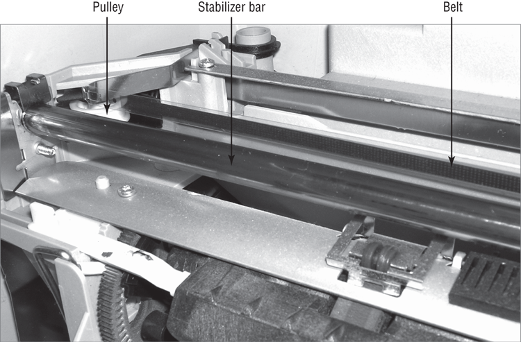
In addition to the motor, a belt is placed around two small wheels or pulleys and attached to the print head carriage. This belt, called the carriage belt, is driven by the carriage motor and moves the print head back and forth across the page while it prints. To keep the print head carriage aligned and stable while it traverses the page, the carriage rests on a small metal stabilizer bar. Figure 10-5 shows the stabilizer bar, carriage belt, and pulleys.
Figure 10-4: A carriage stepper motor
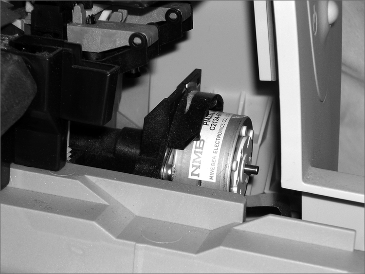
Figure 10-5: Stabilizer bar, carriage belt, and pulleys in a bubble-jet printer
Paper-Feed Mechanism
In addition to getting the ink onto the paper, the printer must have a way to get the paper into the printer. That’s where the paper-feed mechanism comes in. The paper-feed mechanism picks up paper from the paper drawer and feeds it into the printer. This component consists of several smaller assemblies. First are the pickup rollers (Figure 10-6), which are several rubber rollers with a slightly flat spot; they rub against the paper as they rotate, and feed the paper into the printer. They work against small cork or rubber patches known as separator pads (Figure 10-7), which help keep the rest of the paper in place so that only one sheet goes into the printer. The pickup rollers are turned on a shaft by the pickup stepper motor.
Figure 10-6: Bubble-jet pickup rollers
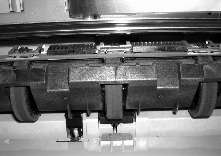
Figure 10-7: Bubble-jet separator pads
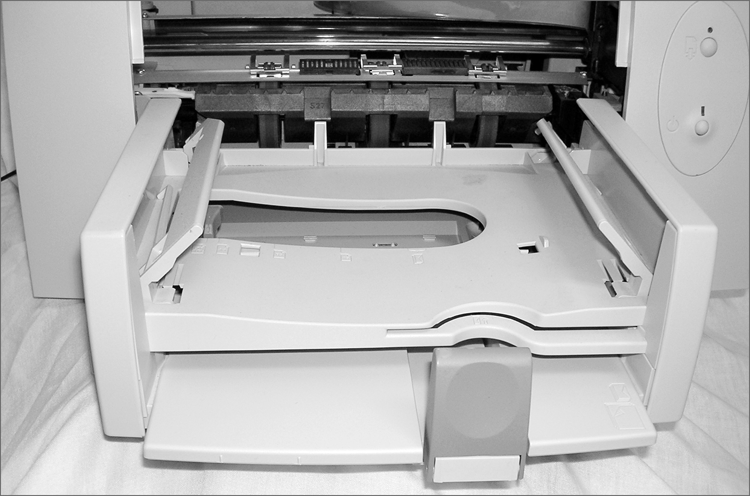
Sometimes the paper that is fed into a bubble-jet printer is placed into a paper tray, which is simply a small plastic tray in the front of the printer that holds the paper until it is fed into the printer by the paper-feed mechanism. On smaller printers, the paper is placed vertically into a paper feeder at the back of the printer; it uses gravity, in combination with feed rollers and separator pads, to get the paper into the printer. No real rhyme or reason dictates which manufacturers use these different parts; some models use them, and some don’t. Generally, more expensive printers use paper trays because they hold more paper. Figure 10-8 shows an example of a paper tray on a bubble-jet printer.
Figure 10-8: A paper tray on a bubble-jet printer
The final parts of the paper-feed mechanism are the paper-feed sensors. These components tell the printer when it is out of paper as well as when a paper jam has occurred during the paper-feed process. Figure 10-9 shows an example of a paper-feed sensor.
Being able to identify the parts of a bubble-jet printer is an important skill for an A+ candidate. In Exercise 10.1 you will identify the parts of a bubble-jet printer. For this exercise, you’ll need a bubble-jet printer.
Figure 10-9: A paper-feed sensor on a bubble-jet printer
Control, Interface, and Power Circuitry
The final component group is the electronic circuitry for printer control, printer interfaces, and printer power. The printer control circuits are usually on a small circuit board that contains all the circuitry to run the stepper motors the way the printer needs them to work (back and forth, load paper and then stop, and so on). These circuits are also responsible for monitoring the health of the printer and reporting that information back to the PC.
The second power component, the interface circuitry (commonly called a port), makes the physical connection to whatever signal is coming from the computer (parallel, serial, network, infrared, and so on) and also connects the physical interface to the control circuitry. The interface circuitry converts the signals from the interface into the datastream that the printer uses.
The last set of circuits the printer uses is the power circuits. Essentially, these conductive pathways convert 110V (in the United States) or 220V (in most of the rest of the world) from a standard wall outlet into the voltages the bubble-jet printer uses, usually 12V and 5V, and distribute those voltages to the other printer circuits and devices that need it. This is accomplished through the use of a transformer. A transformer, in this case, takes the 110V AC current and changes it to 12V DC (among others). This transformer can be either internal (incorporated into the body of the printer) or external. Either design can be used in today’s bubble-jets, although the integrated design is preferred because it is simpler and doesn’t show the bulky transformer.
The Bubble-Jet Printing Process
Just as with other types of printing, the bubble-jet printing process consists of a set of steps the printer must follow in order to put the data onto the page being printed. The following steps take place whenever you click the Print button in your favorite software (like Microsoft Word or Internet Explorer):
Some nicer models of bubble-jet printers will have a duplexing assembly attached to them, usually at the back of the printer. It’s used for two-sided printing. After the first page is printed, it’s fed into the duplexing assembly, turned over, and fed back into the paper feed assembly. Then the second page can be printed on the back side of the original piece of paper. It’s a fancy attachment that gives your bubble-jet more functionality.
Laser Printers
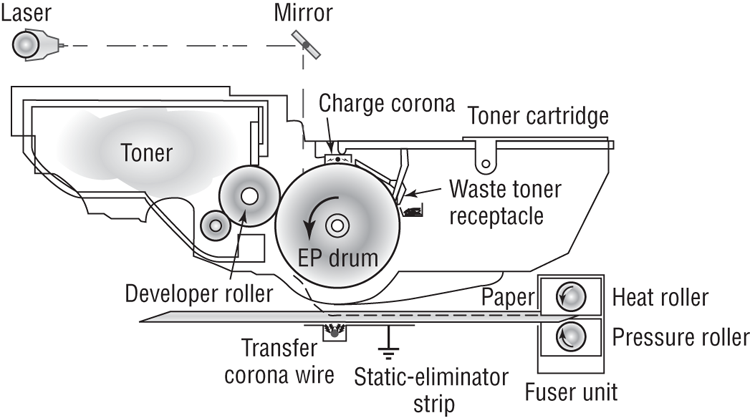
Laser printers and inkjet printers are referred to as page printers because they receive their print job instructions one page at a time rather than receiving instructions one line at a time. There are two major types of page printers that use the electrophotographic (EP) print process. The first uses a laser to scan the image onto a photosensitive drum, and the second uses an array of light-emitting diodes (LEDs) to create the image on the drum. Even though they write the image in different ways, both types still follow the EP print process. Since the A+ exam focuses on the EP print process and not on differences between laser and LED, we’ll focus on the same here.
Xerox, Hewlett-Packard, and Canon were pioneers in developing the laser printer technology we use today. Scientists at Xerox developed the electrophotographic (EP) process in 1971. The first successful desktop laser printer was introduced by HP in 1984 using Canon hardware that used the EP process. This technology uses a combination of static electric charges, laser light, and a black powdery ink-like substance called toner. Printers that use this technology are called EP process laser printers, or just laser printers. Every laser printer technology has its foundations in the EP printer process.
Let’s discuss the basic components of the EP laser printer and how they operate so you can understand the way an EP laser printer works.
Basic Components
Most printers that use the EP process contain nine standard assemblies: the toner cartridge, laser scanner, high-voltage power supply, DC power supply, paper transport assembly (including paper-pickup rollers and paper-registration rollers), transfer corona, fusing assembly, printer controller circuitry, and ozone filter. Let’s discuss each of the components individually before we examine how they all work together to make the printer function.
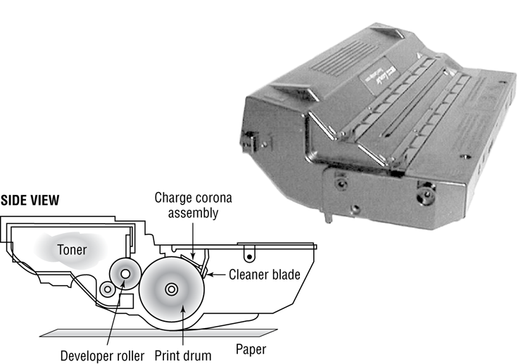
The Toner Cartridge
The EP toner cartridge (Figure 10-10), as its name suggests, holds the toner. Toner is a black carbon substance mixed with polyester resins to make it flow better and iron oxide particles to make it sensitive to electrical charges. These two components make the toner capable of being attracted to the photosensitive drum and of melting into the paper. In addition to these components, toner contains a medium called the developer (also called the carrier), which carries the toner until it is used by the EP process. The toner cartridge also contains the EP print drum. This drum is coated with a photosensitive material that can hold a static charge when not exposed to light but cannot hold a charge when it is exposed to light—a curious phenomenon and one that EP printers exploit for the purpose of making images. Finally, the drum assembly contains a cleaning blade that continuously scrapes the used toner off the photosensitive drum to keep it clean.
Figure 10-10: An EP toner cartridge
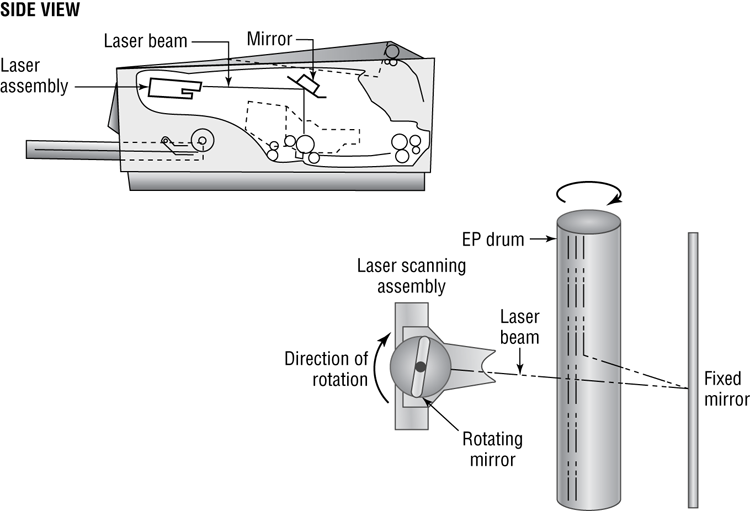
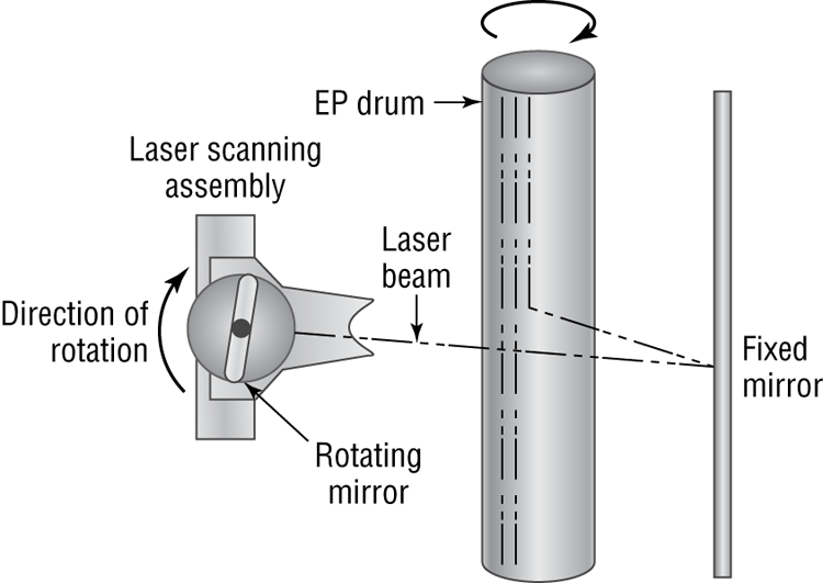
The Laser Scanning Assembly
As we mentioned earlier, the EP photosensitive drum can hold a charge if it’s not exposed to light. It is dark inside an EP printer, except when the laser scanning assembly shines on particular areas of the photosensitive drum. When it does that, the drum discharges, but only in the area that has been exposed. As the drum rotates, the laser scanning assembly scans the laser across the photosensitive drum, writing the image onto it. Figure 10-11 shows the laser scanning assembly.
High-Voltage Power Supply (HVPS)
The EP process requires high-voltage electricity. The high-voltage power supply (HVPS) provides the high voltages used during the EP process. This component converts AC current from a standard wall outlet (120V and 60Hz) into higher voltages that the printer can use. This high voltage is used to energize both the charging corona and the transfer corona.
Figure 10-11: The EP laser scanning assembly (side view and simplified top view)
DC Power Supply (DCPS)
The high voltages used in the EP process can’t power the other components in the printer (the logic circuitry and motors). These components require low voltages, between +5 VDC and +24VDC. The DC power supply (DCPS) converts house current into three voltages: +5VDC and –5VDC for the logic circuitry and +24VDC for the paper-transport motors. This component also runs the fan that cools the internal components of the printer.
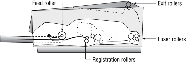
Paper-Transport Assembly
The paper-transport assembly is responsible for moving the paper through the printer. It consists of a motor and several rubberized rollers that each performs a different function.
The first type of roller found in most laser printers is the feed roller, or paper-pickup roller (Figure 10-12). This D-shaped roller, when activated, rotates against the paper and pushes one sheet into the printer. This roller works in conjunction with a special rubber separator pad to prevent more than one sheet from being fed into the printer at a time.
Another type of roller that is used in the printer is the registration roller (also shown in Figure 10-12). There are actually two registration rollers, which work together. These rollers synchronize the paper movement with the image-formation process in the EP cartridge. The rollers don’t feed the paper past the EP cartridge until the cartridge is ready for it.
Both of these rollers are operated with a special electric motor known as an electronic stepper motor. This type of motor can accurately move in very small increments. It powers all the paper-transport rollers as well as the fuser rollers.
Figure 10-12: Paper-transport rollers
The Transfer Corona Assembly
When the laser writes the images on the photosensitive drum, the toner then sticks to the exposed areas; we’ll cover this in the next section, “Electrophotographic (EP) Print Process.” How does the toner get from the photosensitive drum onto the paper? The transfer corona assembly (Figure 10-13) is given a high-voltage charge, which is transferred to the paper, which in turn pulls the toner from the photosensitive drum.
Figure 10-13: The transfer corona assembly
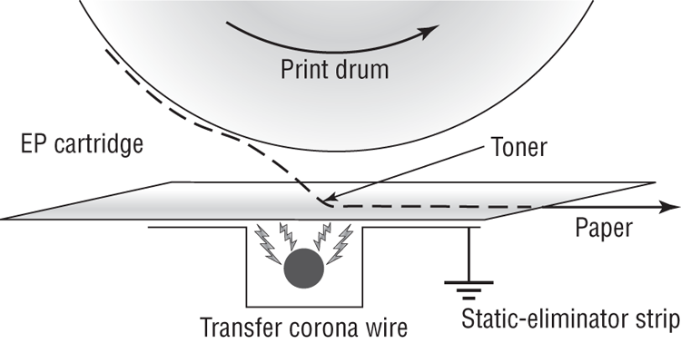
Included in the transfer corona assembly is a static-charge eliminator strip that drains away the charge imparted to the paper by the corona. If you didn’t drain away the charge, the paper would stick to the EP cartridge and jam the printer.
There are two types of transfer corona assemblies: those that contain a transfer corona wire and those that contain a transfer corona roller. The transfer corona wire is a small-diameter wire that is charged by the HVPS. The wire is located in a special notch in the floor of the laser printer (under the EP print cartridge). The transfer corona roller performs the same function as the transfer corona wire, but it’s a roller rather than a wire. Because the transfer corona roller is directly in contact with the paper, it supports higher speeds. For this reason, the transfer corona wire is infrequently used in laser printers today.
Fusing Assembly
The toner in the EP toner cartridge will stick to just about anything, including paper. This is true because the toner has a negative static charge and most objects have a net positive charge. However, these toner particles can be removed by brushing any object across the page. This could be a problem if you want the images and letters to stay on the paper permanently!
To solve this problem, EP laser printers incorporate a device known as a fuser (Figure 10-14), which uses two rollers that apply pressure and heat to fuse the plastic toner particles to the paper. You may have noticed that pages from either a laser printer or a copier (which uses a similar device) come out warm. This is because of the fuser.
Figure 10-14: The fuser

The fuser is made up of three main parts: a halogen heating lamp, a Teflon-coated aluminum fusing roller, and a rubberized pressure roller. The fuser uses the halogen lamp to heat the fusing roller to between 329° F (165° C) and 392° F (200° C). As the paper passes between the two rollers, the pressure roller pushes the paper against the fusing roller, which melts the toner into the paper.
Printer Controller Circuitry
Another component in the laser printer we need to discuss is the printer controller assembly. This large circuit board converts signals from the computer into signals for the various assemblies in the laser printer, using a process known as rasterizing. This circuit board is usually mounted under the printer. The board has connectors for each type of interface and cables to each assembly.
When a computer prints to a laser printer, it sends a signal through a cable to the printer controller assembly. The controller assembly formats the information into a page’s worth of line-by-line commands for the laser scanner. The controller sends commands to each of the components, telling them to wake up and begin the EP print process.
Ozone Filter
Your laser printer uses various high-voltage biases inside the case. As anyone who has been outside during a lightning storm can tell you, high voltages create ozone. Ozone is a chemically reactive gas that is created by the high-voltage coronas (charging and transfer) inside the printer. Because ozone is chemically reactive and can severely reduce the life of laser printer components, many older laser printers contain a filter to remove ozone gas from inside the printer as it is produced. This filter must be removed and cleaned with compressed air periodically (cleaning it whenever the toner cartridge is replaced is usually sufficient). Most newer laser printers don’t have ozone filters. This is because these printers don’t use transfer corona wires but instead use transfer corona rollers, which dramatically reduce ozone emissions.
Duplexing Assembly
Any laser printer worth its money today can print on both sides of the paper. This is accomplished through the use of a duplexing assembly. Usually located inside or on the back of the printer, the assembly is responsible for taking the paper, turning it over, and feeding back into the printer so the second side can be printed.
Electrophotographic (EP) Print Process
The EP print process is the process by which an EP laser printer forms images on paper. It consists of six major steps, each for a specific goal. Although many different manufacturers call these steps different things or place them in a different order, the basic process is still the same. Here are the steps in the order you will see them on the exam:

Before any of these steps can begin, however, the controller must sense that the printer is ready to start printing (toner cartridge installed, fuser warmed to temperature, and all covers in place). Printing cannot take place until the printer is in its ready state, usually indicated by an illuminated Ready LED light or a display that says something like 00 READY (on HP printers). The computer sends the print job to the printer, which begins processing the data. As it’s processing the data, the print process steps begin.
Step 1: Cleaning
In the first part of the laser print process, a rubber blade inside the EP cartridge scrapes any toner left on the drum into a used toner receptacle inside the EP cartridge, and a fluorescent lamp discharges any remaining charge on the photosensitive drum (remember that the drum, being photosensitive, loses its charge when exposed to light). This step is called the cleaning step (Figure 10-15).
Figure 10-15: The cleaning step of the EP process
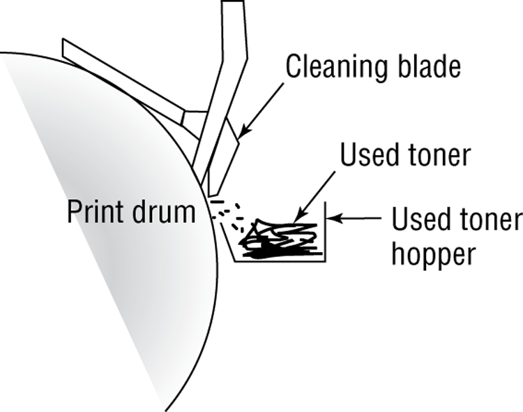
The EP cartridge is constantly cleaning the drum. It may take more than one rotation of the photosensitive drum to make an image on the paper. The cleaning step keeps the drum fresh for each use. If you didn’t clean the drum, you would see ghosts of previous pages printed along with your image.
Step 2: Charging
The next step in the EP process is the charging step (Figure 10-16). In this step, a special wire or roller (called a charging corona) within the EP toner cartridge (above the photosensitive drum) gets a high voltage from the HVPS. It uses this high voltage to apply a strong, uniform negative charge (around –600VDC) to the surface of the photosensitive drum.
Step 3: Writing
Next is the writing step. In this step, the laser is turned on and scans the drum from side to side, flashing on and off according to the bits of information the printer controller sends it as it communicates the individual bits of the image. Wherever the laser beam touches, the photosensitive drum’s charge is severely reduced from –600VDC to a slight negative charge (around –100VDC). As the drum rotates, a pattern of exposed areas is formed, representing the image to be printed. Figure 10-17 shows this process.
Figure 10-16: The charging step of the EP process
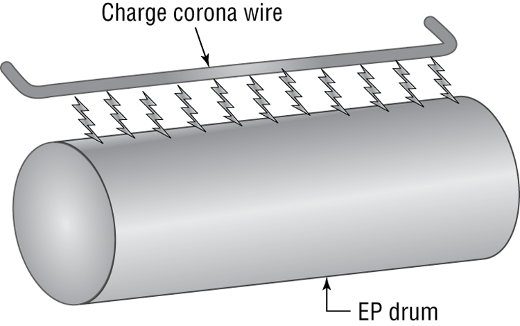
Figure 10-17: The writing step of the EP process
At this point, the controller sends a signal to the pickup roller to feed a piece of paper into the printer, where it stops at the registration rollers.
Step 4: Developing
Now that the surface of the drum holds an electrical representation of the image being printed, its discrete electrical charges need to be converted into something that can be transferred to a piece of paper. The EP process step that accomplishes this is the developing step (Figure 10-18). In this step, toner is transferred to the areas that were exposed in the writing step.
A metallic roller called the developing roller inside an EP cartridge acquires a –600VDC charge (called a bias voltage) from the HVPS. The toner sticks to this roller because there is a magnet located inside the roller and because of the electrostatic charges between the toner and the developing roller. While the developing roller rotates toward the photosensitive drum, the toner acquires the charge of the roller (–600VDC). When the toner comes between the developing roller and the photosensitive drum, the toner is attracted to the areas that have been exposed by the laser (because these areas have a lesser charge, –100VDC). The toner also is repelled from the unexposed areas (because they are at the same –600VDC charge and like charges repel). This toner transfer creates a fog of toner between the EP drum and the developing roller.
Figure 10-18: The developing step of the EP process
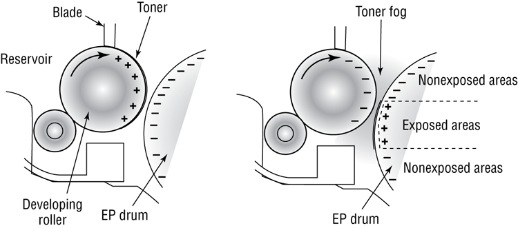
The photosensitive drum now has toner stuck to it where the laser has written. The photosensitive drum continues to rotate until the developed image is ready to be transferred to paper in the next step.
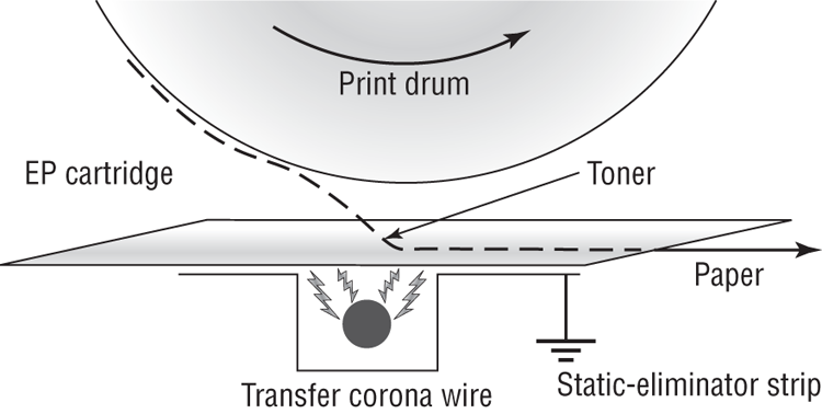
Step 5: Transferring
At this point in the EP process, the developed image is rotating into position. The controller notifies the registration rollers that the paper should be fed through. The registration rollers move the paper underneath the photosensitive drum, and the process of transferring the image can begin; this is the transferring step.
The controller sends a signal to the charging corona wire or roller (depending on which one the printer has) and tells it to turn on. The corona wire/roller then acquires a strong positive charge (+600VDC) and applies that charge to the paper. The paper, thus charged, pulls the toner from the photosensitive drum at the line of contact between the roller and the paper because the paper and toner have opposite charges. Once the registration rollers move the paper past the corona wire, the static-eliminator strip removes all charge from that line of the paper. Figure 10-19 details this step. If the strip didn’t bleed this charge away, the paper would attract itself to the toner cartridge and cause a paper jam.
The toner is now held in place by weak electrostatic charges and gravity. It will not stay there, however, unless it is made permanent, which is the reason for the fusing step.
Figure 10-19: The transferring step of the EP process
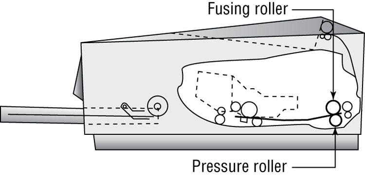
Step 6: Fusing
In the final step, the fusing step, the toner image is made permanent. The registration rollers push the paper toward the fuser rollers. Once the fuser grabs the paper, the registration rollers push for only a short time more. The fuser is now in control of moving the paper.
As the paper passes through the fuser, the 350° F fuser roller melts the polyester resin of the toner, and the rubberized pressure roller presses it permanently into the paper (Figure 10-20). The paper continues through the fuser and eventually exits the printer.
Figure 10-20: The fusing step of the EP process
Once the paper completely exits the fuser, it trips a sensor that tells the printer to finish the EP process with the cleaning step. At this point, the printer can print another page, and the EP process can begin again.
Summary of the EP Print Process
Figure 10-21 summarizes all the parts involved in the EP printing process. First, the printer uses a rubber scraper to clean the photosensitive drum. Then the printer places a uniform –600VDC charge on the photosensitive drum by means of a charging corona. The laser “paints” an image onto the photosensitive drum, discharging the image areas to a much lower voltage (–100VDC). The developing roller in the toner cartridge has charged (–600VDC) toner stuck to it. As it rolls the toner toward the photosensitive drum, the toner is attracted to (and sticks to) the areas of the photosensitive drum that the laser has discharged. The image is then transferred from the drum to the paper at its line of contact by means of the transfer corona wire (or corona roller) with a +600VDC charge. The static-eliminator strip removes the high, positive charge from the paper, and the paper, now holding the image, moves on. The paper then enters the fuser, where a fuser roller and the pressure roller make the image permanent. The paper exits the printer, and the printer begins printing the next page or returns to its ready state.
Figure 10-21: The EP print process
Thermal Printers
The types of printers you have learned about so far in this chapter account for 90 percent of all printers that are used with home or office computers and that you will see as a repair technician. The other 10 percent consist of other types of printers that primarily differ by the method they use to put colored material on the paper to represent what is being printed. Examples of these include solid ink, dye sublimation, and thermal printers. Keep in mind that for the most part, these printers operate like other printers in many ways: They all have a paper-feed mechanism (sheet-fed or roll); they all require consumables such as ink or toner and paper; they all use the same interfaces, for the most part, as other types of printers; and they are usually about the same size.
Thermal printing technology is used in many Point of Sale terminals and older fax machines (newer fax machines usually use inkjet or laser technology). They print on a kind of special, waxy paper that comes on a roll; the paper turns black when heat passes over it. Thermal printers work by using a print head the width of the paper. When it needs to print, a heating element heats certain spots on the print head. The paper below the heated print head turns black in those spots. As the paper moves through the printer, the pattern of blackened spots forms an image on the page of what is being printed. Another type of thermal printer uses a heat-sensitive ribbon instead of heat-sensitive paper. A thermal print head melts wax-based ink from the ribbon onto the paper. These are called thermal transfer or thermal wax-transfer printers.
Thermal direct printers typically have long lives because they have few moving parts. The only unique part that you might not be as familiar with is the paper feed assembly, which oftentimes needs to accommodate a roll of paper instead of sheets. The paper is somewhat expensive, doesn’t last long (especially if it is left in a very warm place, like a closed car in summer), and produces poorer-quality images than most of the other printing technologies.