
Identifying Common Network Hardware
We have looked at the types of networks, network topologies, and the way communications are handled. That’s all of the logical stuff. To really get computers to talk to each other requires hardware. Every computer on the network needs to have a network adapter of some type. In many cases, you also need some sort of cable to hook them together. (Wireless networking is the exception, but at the back end of a wireless network there are still components wired together.) And finally, you might also need connectivity devices to attach several computers or networks to each other.
Network Interface Cards (NICs)
The network interface card (NIC) provides the physical interface between computer and cabling. It prepares data, sends data, and controls the flow of data. It can also receive and translate data into bytes for the CPU to understand. NICs come in many shapes and sizes.
Different NICs are distinguished by the PC bus type and the network for which they are used. The following sections describe the role of NICs and how to evaluate them. The following factors should be taken into consideration:
- Compatibility
- Performance
- Sending and controlling data
- Configuration
- Drivers
Compatibility
The first thing you need to determine is whether the NIC will fit the bus type of your PC. If you have more than one type of bus in your PC (for example, a combination PCI/PCI Express), use a NIC that fits into the fastest type (the PCI Express, in this case). This is especially important in servers because the NIC can quickly become a bottleneck if this guideline isn’t followed.
More and more computers are using network cards that have either PC Card or USB interfaces. For laptop computers that don’t otherwise have a network card built in to them, these small portable cards are very handy.

Network Interface Card Performance
The most important goal of the network adapter card is to optimize network performance and minimize the amount of time needed to transfer data packets across the network. The key is to ensure that you get the fastest card you can for the type of network you’re on. For example, if your wireless network supports 802.11b/g/n, make sure to get an 802.11n card because it’s the fastest.
Sending and Controlling Data
For two computers to send and receive data, the cards must agree on several things:
- The maximum size of the data frames
- The amount of data sent before giving confirmation
- The time needed between transmissions
- The amount of time to wait before sending confirmation
- The speed at which data transmits
If the cards can agree, the data is sent successfully. If the cards cannot agree, the data is not sent.
To successfully send data on the network, all NICs need to use the same media access method (such as Ethernet or token ring) and be connected to the same piece of cable. This usually isn’t a problem because the vast majority of network cards sold today are Ethernet. If you were to try to use cards of different types (for example, one Ethernet and one Token Ring), neither of them would be able to communicate with the other unless you had a separate hardware device between them that could translate.
In addition, NICs can send data using either full-duplex or half-duplex mode. Half-duplex communication means that between the sender and receiver, only one of them can transmit at any one time. In full-duplex communication, a computer can send and receive data simultaneously. The main advantage of full-duplex over half-duplex communication is performance. NICs (specifically Fast Ethernet NICs) can operate twice as fast (200Mbps) in full-duplex mode as they do normally in half-duplex mode (100Mbps).
NIC Configuration
Each card must have a unique hardware address, called a MAC address. If two cards on the same network have the same hardware address, neither one will be able to communicate. For this reason, the IEEE has established a standard for hardware addresses and assigns blocks of these addresses to NIC manufacturers, who then hard-wire the addresses into the cards.
NIC Drivers
For the computer to use the NIC, it is very important to install the proper device drivers. These drivers communicate directly with the network redirector and adapter. They operate in the Media Access Control sublayer of the Data Link layer of the OSI model.
Cables, Connectors, and Cabling Tools
When the data is passing through the OSI model and reaches the Physical layer, it must find its way onto the medium that is used to physically transfer data from computer to computer. This medium is called the cable (or in the case of wireless networks, the air). It is the NIC’s role to prepare the data for transmission, but it is the cable’s role to properly move the data to its intended destination. There are three main types of physical cabling to discuss: coaxial cable, twisted-pair cable, and fiber-optic cable. (Wireless communications will be covered in Chapter 8, “Installing Wireless and SOHO Networks.”) The three cabling types will be discussed in the following sections.
Coaxial
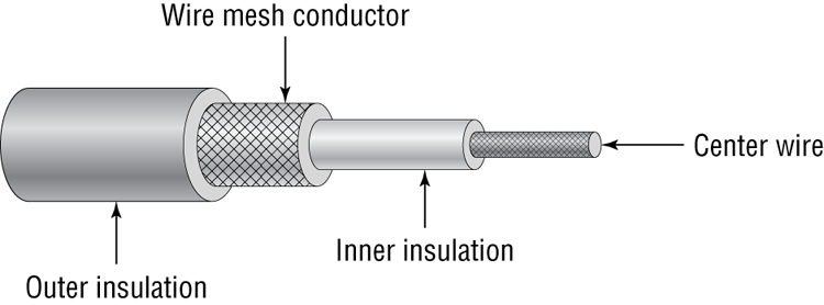
Coaxial cable (or coax) contains a center conductor core made of copper, which is surrounded by a plastic jacket with a braided shield over it (as shown in Figure 6-12). Either Teflon or a plastic coating covers this metal shield.
Figure 6-12: Coaxial cable
Common network cables are covered with a plastic called polyvinyl chloride (PVC). While PVC is flexible, fairly durable, and inexpensive, it has a nasty side effect in that it produces poisonous gas when burned. An alternative is a Teflon-type covering that is frequently referred to as a plenum-rated coating. That simply means that the coating does not produce toxic gas when burned and is rated for use in ventilation plenums that carry breathable air. This type of cable is more expensive but may be mandated by electrical code whenever cable is hidden in walls or ceilings.
Coax Cable Specifications
Coaxial cable is available in various specifications that are rated according to the Radio Guide (RG) system, which was originally developed by the US military. The thicker the copper, the farther a signal can travel—and with that comes a higher cost and a less-flexible cable.
When coax cable was popular for networking, there were two standards that had fairly high use: RG-8 (thicknet) and RG-58A/U (thinnet). Thicknet had a maximum segment distance of 500 meters and was used primarily for network backbones. Thinnet was more often used in a conventional physical bus. A thinnet segment could span 185 meters. Table 6-2 shows the different types of RG cabling and their uses.
Table 6-2: Coax RG Types
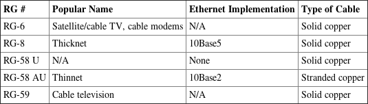
Coaxial networking has all but gone the way of the dinosaur. The only two coaxial cable types used today are RG-6 and RG-59. Of the two, RG-6 can run longer distances and support digital signals. RG-59 is considered adequate for analog cable TV but not digital.
Coax Connector Types
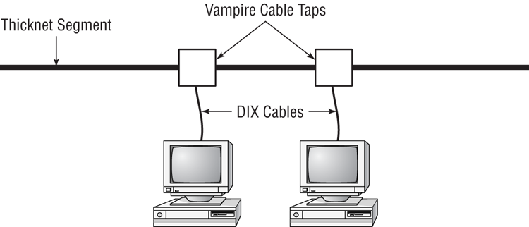
Thicknet was a bear to work with. Not only was it highly inflexible, but you needed to use a connector called a vampire tap. A vampire tap is so named because a metal tooth sinks into the cable, thus making the connection with the inner conductor. The tap is connected to an external transceiver that in turn has a 15-pin AUI connector (also called DIX or DB15 connector) to which you attach a cable that connects to the station (shown in Figure 6-13). DIX got its name from the companies that worked on this format—Digital, Intel, and Xerox.
Figure 6-13: Thicknet and vampire taps
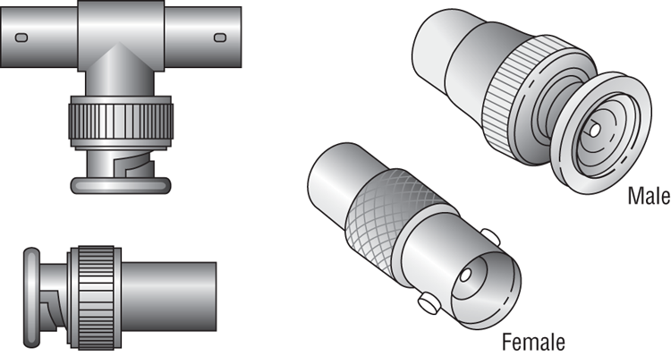
Thinnet coax was much easier to work with. Generally, thinnet cables used a BNC connector (see Figure 6-14) to attach to a T-shaped connector that attached to the workstation. The other side of the T-connector would either continue on with another thinnet segment or be capped off with a terminator. It is beyond our scope to settle the long-standing argument over the meaning of the abbreviation BNC. We have heard Bayonet Connector, Bayonet Nut Connector, and British Naval Connector, among others. What is relevant is that the BNC connector locks securely with a quarter-twist motion.
Figure 6-14: Male and female BNC connectors, T-connector, and terminator
The other type of coax connector is called an F-connector (shown in Figure 6-15) and is used with cable TV. The exposed end of the copper cable is pushed into the receptacle, and the connector is threaded so it can screw into place.
Figure 6-15: An F-connector

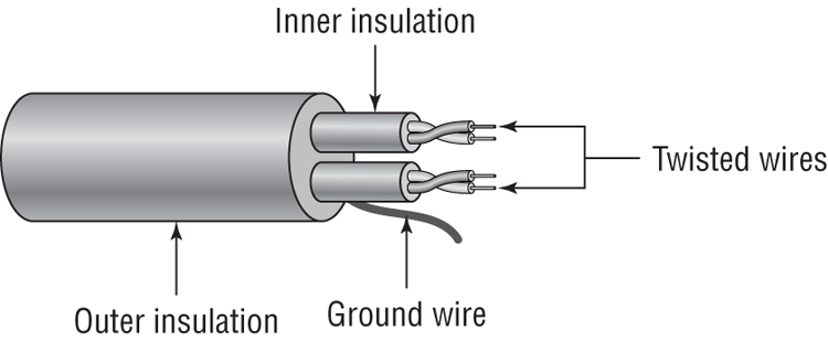
Twisted Pair
Twisted pair is the most popular type of cabling to use because of its flexibility and low cost. It consists of several pairs of wire twisted around each other within an insulated jacket, as shown in Figure 6-16.
There are two different types of twisted-pair: shielded twisted-pair (STP) and unshielded twisted-pair (UTP). Both types of cable have two or four pairs of twisted wires going through them. The difference is that STP has an extra layer of braided foil shielding surrounding the wires to decrease electrical interference. UTP has a PVC or plenum coating but no foil shield to protect it from interference.
Figure 6-16: Twisted-pair cable
Twisted-Pair Cable Specifications
There aren’t any STP standards that you really need to know about, either for the test or real-life situations. UTP is a different animal. It comes in eight grades to offer different levels of performance and protection against electrical interference:
- Category 1 contains two twisted pairs. Is for voice-only transmissions and is in many legacy phone systems today.
- Category 2 is the lowest-grade cable able to have four pairs of wires. (Every other CAT rating since CAT-2 has four pairs.) It can handle data transmission at speeds up to 4Mbps.
- Category 3 is able to transmit data at speeds up to 10Mbps. It was popular for 10BaseT installations before CAT-5 came out.
- Category 4 is able to transmit data at speeds up to 16Mbps.
- Category 5 is able to transmit data at speeds up to 100Mbps.
- Category 5e is able to transmit data at speeds up to 1Gbps. The enhancement over CAT-5 is that the four twisted pairs of copper wire are physically separated and contain more twists per foot. This provides maximum interference protection.
- Category 6 is able to transmit data at speeds up to 10Gbps. Its four twisted pairs of copper wire are oriented differently than in CAT-5e. You can use it as a backbone to connect different parts of your network together, such as those on different floors of a building.
- Category 6a can also handle 10Gbps speed, but at longer distances (up to 100 meters) than CAT-6 can.
Each of these levels has a maximum transmission distance of 100 meters. Do note, however, that if you want to run 10GBaseT over CAT-6 you won’t get that much distance—about 55m.
Twisted-Pair Connector Types
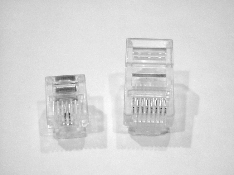
Twisted-pair cabling uses a connector type called an RJ (registered jack) connector. You are probably familiar with RJ connectors. Most land-line phones connect with an RJ-11 connector. The connector used with UTP cable is called RJ-45. The RJ-11 has room for two pairs (four wires), and the RJ-45 has room for four pairs (eight wires).
In almost every case, UTP uses RJ connectors; a crimper is used to attach an RJ connector to a cable. Higher-quality crimping tools have interchangeable dies for both types of connectors. Figure 6-17 shows an RJ-11 and an RJ-45 connector.
Figure 6-17: RJ-11 and RJ-45 connectors
Wiring Standards
Twisted-pair cables are unique in today’s network environment in that they use multiple physical wires. Those eight wires need to be in the right places in the RJ-45 connector or it’s very likely that the cable will not work properly. To ensure consistency in the industry, two standards have been developed: 568A and 568B.
Older implementations using UTP used only two pairs of wires, and those two pairs were matched to pins 1, 2, 3, and 6 in the connector. Newer applications such as Voice over IP and Gigabit Ethernet use all four pairs of wires, so you need to make sure they’re all where they’re supposed to be.
If you’re creating a regular network patch cable to connect a computer to a hub or a switch, both sides need to have the same pinout. For that, follow the 568A standard as shown in Figure 6-18.
If you are going to create a crossover cable, you need to cross pin 1 to pin 3 and pin 2 to pin 6 on one side of the cable only. This is to get the “send” pins matched up with the “receive” pins on the other side, and vice versa. For easier visualization, look at Figure 6-19.
Figure 6-18: 568A standard
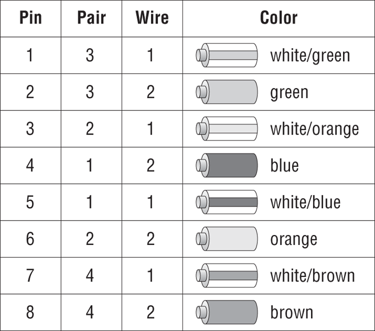
Figure 6-19: 568B standard
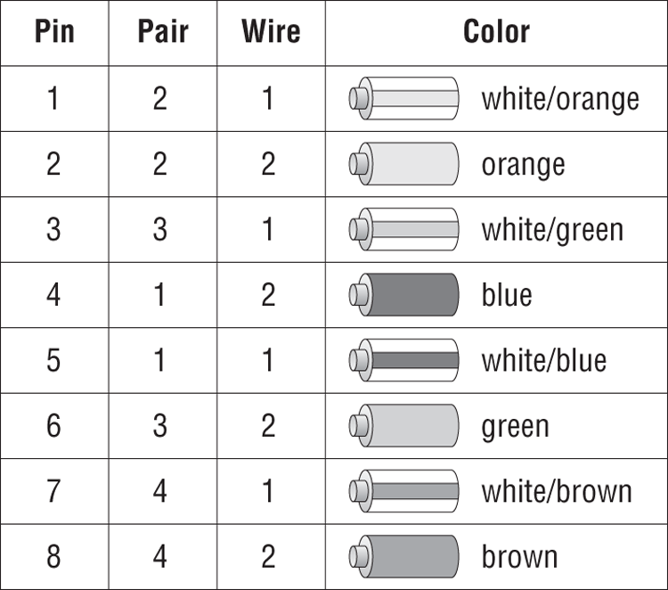
Crossover cables are used to connect a computer to a computer, hub to hub, switch to switch, hub to switch, or computer directly to a router. The key thing to remember is that a patch (straight-through) cable is the same on both ends. A crossover cable is different on each end.
Fiber-Optic
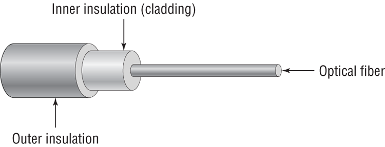
Fiber-optic cabling has been called one of the best advances in cabling. It consists of a thin, flexible glass or plastic fiber surrounded by a rubberized outer coating (see Figure 6-20). It provides transmission speeds from 100Mbps to 10Gbps and a maximum distance of several miles. Because it uses pulses of light instead of electric voltages to transmit data, it is immune to electrical interference and to wiretapping.
Figure 6-20: Fiber-optic cable
Fiber-optic cable has not been too widely adopted yet for local area networks, however, because of its high cost of installation. Fiber-optic cabling is often used in networks that need extremely fast transmission rates or transmissions over long distances or have had problems with electrical interference in the past.
Fiber-Optic Cable Specifications
Fiber-optic cable comes in two varieties: single-mode or multimode. The term mode refers to the bundles of light that enter the fiber-optic cable. Single-mode fiber (SMF) cable uses only a single mode of light to propagate through the fiber cable, whereas multimode fiber allows multiple modes (paths) of light to propagate simultaneously. In multimode fiber-optic cable, the light bounces off the cable walls as it travels through the cable, which causes the signal to weaken more quickly.
Multimode fiber is most often used as horizontal cable. It permits multiple modes of light to propagate through the cable, which shortens cable distances and delivers less available bandwidth. Devices that use MMF cable typically use light-emitting diodes (LEDs) to generate the light that travels through the cable; however, lasers with multimode fiber-optic cable are now being used in higher-bandwidth network devices such as Gigabit Ethernet. MMF can transmit up to 10Gbps for up to 550 meters, depending on the standard used.
Single-mode fiber cable is commonly used as backbone cabling; it is also usually the cable type used in phone systems. Light travels through single-mode fiber-optic cable using only a single mode, meaning it travels straight down the fiber and does not bounce off the cable walls. Because only a single mode of light travels through the cable, single-mode fiber-optic cable supports higher bandwidth at longer distances than multimode fiber-optic cable does. Devices that use single-mode fiber-optic cable typically use lasers to generate the light that travels through the cable. SMF can transmit up to 10Gbps for up to 40 kilometers, depending on the standard used.
Fiber-Optic Connector Types
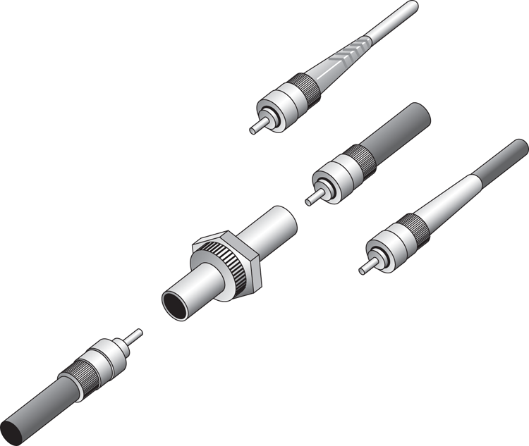
There are literally dozens of fiber-optic connectors out there because it seemed that every producer wanted its proprietary design to become “the standard.” Three of the most commonly-used ones are ST, SC, and LC.
The straight tip (ST) fiber-optic connector, developed by AT&T, is probably the most widely used fiber-optic connector. It uses a BNC attachment mechanism that makes connections and disconnections fairly easy. The ease of use of the ST is one of the attributes that makes this connector so popular. Figure 6-21 shows some examples of ST connectors.
Figure 6-21: Examples of ST connectors
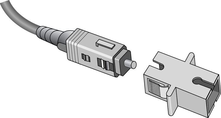
The subscriber connector (SC), also sometimes known as a square connector, is a type of fiber-optic connector, as shown in Figure 6-22. SCs are latched connectors, making it virtually impossible for you to pull out the connector without releasing its latch, usually by pressing a button or release. SCs work with either single-mode or multimode optical fibers. They aren’t as popular as ST connectors for LAN connections.
Figure 6-22: A sample SC
The last type of connector you need to be familiar with is the local connector (LC), which was developed by Lucent Technologies. It is a mini form factor (MFF) connector, especially popular for use with Fibre-Channel adapters, fast storage area networks, and Gigabit Ethernet adapters. It is shown in Figure 6-23.
Figure 6-23: LC fiber connector

Cabling Tools
Now that you’re familiar with the different types of cables used in networking, let’s take a minute to examine a few tools you can use to troubleshoot your cables or your general connectivity.
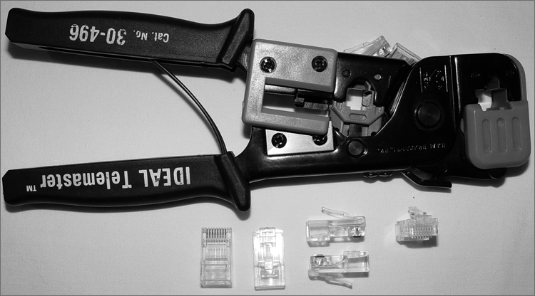
Crimper
A crimper is a very handy tool for helping you put connectors on the end of a cable. Many crimpers will be a combination tool that strips and snips wires as well as crimps the connector on to the end. Figure 6-24 shows you one of these tools.
Figure 6-24: A UTP crimper
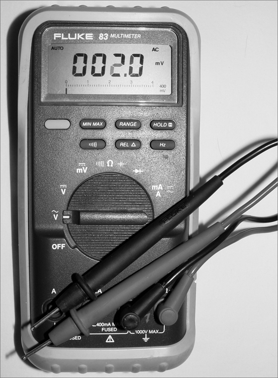
Multimeter
Multimeters are very versatile electronic measuring tools. A multimeter can measure voltage, current, and resistance on a wire. There are a wide variety of types and qualities on the market, everywhere, from economical $10 versions to ones that cost several thousand dollars. Figure 6-25 shows a basic multimeter.
Figure 6-25: A multimeter
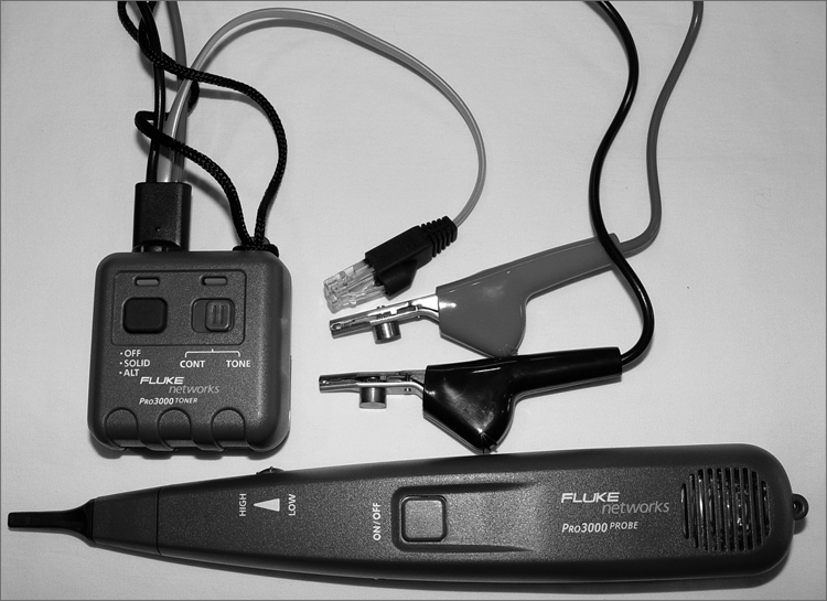
Toner Probe
If you need to trace a wire in a wall from one location to another, a toner probe is the tool for you. Shown in Figure 6-26, it consists of two pieces: a tone generator and a probe. Because it’s so good at tracking, you will sometimes hear this referred to as a “fox and hound.”
Cable Tester
Cable testers are indispensable tools for any network technician. Usually you would use a cable tester before you install a cable to make sure it works. Of course, you can also test them after they’ve been run as well. A decent cable tester will tell you the type of cable, and more elaborate models will have connectors for multiple types of cables.
Figure 6-26: A toner probe
Loopback Plug
Of the devices listed in Objective 2.10, this is the only one that doesn’t specifically test cables. Considering that it’s part of the objectives though, it makes as much sense to cover it here as it would anywhere else.
A loopback plug is for testing the ability of a network adapter to send and receive. The plug gets plugged into the NIC, and then a loopback test is performed using troubleshooting software. You can then tell if the card is working properly or not. Figure 6-27 shows an Ethernet loopback plug, but they are made for fiber-optic NICs as well.
Figure 6-27: An Ethernet loopback plug
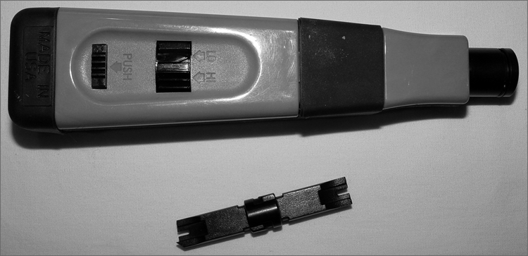
Punch-Down Tool
Last but not least is the punch-down tool. It’s not a testing tool but one that allows you to connect (i.e., punch down) the exposed ends of a wire into a wiring harnesses, such as a 110 block (used many times in connectivity closets to help simplify the tangled mess of cables). Figure 6-28 shows the tool and its changeable bit.
Figure 6-28: A punch-down tool
Networking Components
Network cabling can link one computer to another, but most networks are far grander in scale than two simple machines. There are a variety of networking devices that provide connectivity to the network, make the network bigger, and offer auxiliary services to end users.
In the following sections, we’re going to classify additional networking components into two broad categories: connectivity devices and auxiliary devices.
Connectivity Devices
We all know that if you want to be part of a computer network, you need to attach to that network somehow. Network cables are one way to accomplish this, but not everyone is in a position to just plug a cable in and go. In addition, if you want to grow your network beyond a few simple connections, you need to use a special class of networking devices known as connectivity devices. These devices allow communications to break the boundaries of local networks and really provide the backbone for nearly all computer networks, regardless of size.
There are several categories of connectivity devices, but we are going to discuss the most important and frequently used:
- Modem
- Access point
- Hub
- Bridge
- Switch
- Router
These connectivity devices have made it possible for users to connect to networks and to lengthen networks to almost unlimited distances.
Modems
If you want to connect to a network or the Internet using plain old phone lines and a dial-up connection, a modem is the device you’ll need. Modems got their name because they modulate and demodulate (mo-dem) digital signals that computers use into analog signals that can be passed over telephone lines. In the early to mid-1990s, modems were practically the only device available to get to the Internet. Many companies also used them to allow users who were not in the office to dial in to the local network.
While modems did provide flexibility, you of course needed to be near a phone line, and speed was an issue. The fastest modems transferred data at 56Kbps. At the time that felt lightning quick, but fortunately our species has moved well beyond that technology. It’s horrifically slow by today’s standards and therefore rarely used.
Access Points
Technically speaking, an access point is any point that allows a user on to a network. The term is commonly used in reference to a wireless access point, which lets users connect to your network via an 802.11 technology. We’ll get deeper into wireless access points and how to configure them in Chapter 8.
Hubs
A hub is a device used to link several computers together. Hubs are very simple devices that possess no real intelligence. They simply repeat any signal that comes in on one port and copy it to the other ports (a process that is also called broadcasting). You’ll sometimes hear them referred to as multiport repeaters. They work at the Physical layer (Layer 1) of the OSI model just as repeaters do.
There are two types of hubs: active and passive. Passive hubs connect all ports together electrically but do not have their own power source. Active hubs use electronics to amplify and clean up the signal before it is broadcast to the other ports.
Bridges
Bridges operate in the Data Link layer (Layer 2) of the OSI model. They join similar topologies and are used to divide network segments into multiple collision domains. Bridges isolate network traffic, preventing unwanted traffic from entering a segment when there are no recipients on that segment.
For example, with 100 people on one Ethernet segment, performance will be mediocre because of the design of Ethernet and the number of workstations that are fighting to transmit. If you use a bridge to divide the segment into two segments of 50 workstations each, the traffic will be much lower on either side and performance will increase.
Bridges are not able to distinguish one protocol from another because higher levels of the OSI model are not available to them. If a bridge is aware of the destination MAC address, it can forward packets to the correct segment; otherwise, it forwards the packets to all segments.
Bridges are more intelligent than repeaters but are unable to move data across multiple networks simultaneously.
The main disadvantage of bridges is that they forward broadcast packets. Broadcasts are addressed to all computers, so the bridge just does its job and forwards the packets. Bridges also cannot perform intelligent path selection, meaning that the path from the sender to the destination will always be the same regardless of network conditions. To stop broadcasts or perform intelligent path selection, you need a router.
Switches
Switches work at Layer 2 as bridges do, and they provide centralized connectivity just as hubs do. They often look similar to hubs, so it’s easy to confuse them. There are big performance differences though. Hubs pass along all traffic, but switches examine the Layer 2 header of the incoming packet and forward it properly to the right port and only that port. This greatly reduces overhead and thus improves performance because there is essentially a virtual connection between sender and receiver. The only downside is that switches forward broadcasts because they are addressed to everyone.
Nearly every hub or switch you will see has one or more status indicator lights on it. If there is a connection to a port of the switch, a light either above the connector or on an LED panel elsewhere on the device will light up. If traffic is crossing the port, the light may flash, or there may be a secondary light that will light up. Many devices can also detect a problem in the connection. If a normal connection produces a green light, a bad connection might produce an amber one.
Routers
Routers are highly intelligent devices that connect multiple network types and determine the best path for sending data. They can route packets across multiple networks and use routing tables to store network addresses to determine the best destination. Routers operate at the Network layer (Layer 3) of the OSI model. Because of this, they make their decisions on what to do with traffic based on logical addresses, such as an IP address.
Routers have a few key functions. One, they connect multiple networks to each other, which none of the other devices we have discussed do. Two, routers do not forward broadcasts. (Switches and bridges break up collision domains, whereas routers break up broadcast domains.) Routers are normally used to connect one LAN to another. Typically, when a WAN is set up, at least two routers are used.
In the last few years, wireless routers have become all the rage for small and home networks. They possess all of the functionality of routers historically associated with networking, but they are relatively inexpensive. We’ll talk more about these in Chapter 8.
Auxiliary Devices
The devices we just talked about are specialized to provide connectivity. This next group of devices adds in features outside of connectivity that can help network users with their daily tasks and protect them from malicious attacks.
NAS
A network-attached storage (NAS) device is a specialized computer that acts like a hard drive directly attached to the network. NAS devices are dedicated for storage only, and while acting as a file server, they can provide additional services such as data backups as well.
Firewall
A firewall is a hardware or software solution that serves as your network’s security guard. They’re probably the most important device on networks that are connected to the Internet. Firewalls can protect you in two ways. They protect your network resources from hackers lurking in the dark corners of the Internet, and they can simultaneously prevent computers on your network from accessing undesirable content on the Internet. At a basic level, firewalls filter packets based on rules defined by the network administrator.
Firewalls can be stand-alone “black boxes,” software installed on a server or router, or some combination of hardware and software. Most firewalls will have at least two network connections: one to the Internet, or public side, and one to the internal network, or private side. Some firewalls have a third network port for a second semi-internal network. This port is used to connect servers that can be considered both public and private, such as web and email servers. This intermediary network is known as a demilitarized zone (DMZ).
Firewalls can be network based in that they protect a group of computers (or an entire network), or they can be host-based. A host-based firewall (such as Windows Firewall) protects only the individual computer on which it’s installed.
A firewall is configured to allow only packets that pass specific security restrictions to get through. By default, most firewalls are configured as default deny, which means that all traffic is blocked unless specifically authorized by the administrator. The basic method of configuring firewalls is to use an access control list (ACL). The ACL is the set of rules that determines which traffic gets through the firewall and which traffic is blocked. ACLs are typically configured to block traffic by IP address, port number, domain name, or some combination of all three.
VoIP Phones
Voice over Internet Protocol (VoIP) is a term that describes technology that delivers voice communications over the Internet. A good VoIP system will allow users to send data, video, and voice all at the same time over the same Internet connection. To facilitate VoIP, many companies have made telephones that hook directly to your network, otherwise known as VoIP phones. It looks like a telephone and acts like a telephone, but it uses your network instead of phone lines.
Internet Appliance
An Internet appliance is a specialized hardware device that exists solely to connect to the Internet. It can be used for typical Internet stuff like web browsing and email. Internet appliances were intended to be lower-cost alternatives to laptop computers. Considering that most mobile devices are Internet capable and the price of laptop and tablet computers has continued to drop, you’re not likely to see a lot of these devices.