13.2. The ITRS Proposal for SOC Design
In addressing the design needs of the 21st century, the consensus opinion represented in the ITRS 2005 report clearly identifies several possible approaches to resolving the rise in design complexity. Two of the key elements the ITRS report identifies are reuse productivity and allowing designers to work at a higher level of abstraction. The most reusable logic-block element the electronics industry has produced to date, by far, is the programmable microprocessor and its brethren (DSPs, microcontrollers, network processors, graphics processors, etc.). By its very nature, the microprocessor can serve in a very wide number of roles through its programmability. The broad use of microprocessors to implement tasks dovetails with the use of high-level programming languages, particularly C and C++, to initially describe the function of both systems and subsystems.
Therefore, it’s no surprise that the ITRS 2005 report plots a rise in “processing elements” for future SOC designs, as shown in Figure 13.1. The numbers shown for processing engines are absolute and the values shown for logic gates and memory bits are normalized to the year 2005. In 2005, the ITRS 2005 report assumes the “typical” SOC in 2005 had 6.5 million gates, which included 16 processing engines. Again, the ITRS estimates are an industry consensus based on input from the semiconductor industry, system vendors, university researchers, and government agencies.
Figure 13.1. The ITRS 2005 report predicts an exponential rise in the number of gates, memory bits, and processing engines used to build an SOC. The numbers shown for processing engines are absolute values. The values shown for logic gates and memory bits are normalized to the year 2005.

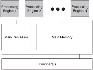
Perhaps more important than the ITRS estimate of the number of processors on future SOCs is the organization’s ideas for how SOCs using those processors will be architected. Figure 13.2 shows one such possible architecture template, taken directly from the ITRS 2005 report. This architecture template replicates the classic, now-obsolete, 20th-century “onebus-fits-all” system-design approach that should be anathema to anyone who has read the preceding 12 chapters of this book. The single bus appearing in Figure 13.2 that ties all of the system’s processing engines together represents a heavily shared resource—one that’s all but certain to become overloaded as tens and then hundreds of processors are connected. A single-bus architecture also fails catastrophically if the bus fails, making built-in fault tolerance impossible. This single-bus system architecture is simply not a good design for multiple-processor SOCs (MPSOCs).
Figure 13.2. All processing elements share the bus in this multiple-processor system. Bandwidth overload is certain as tens and then hundreds of processors are connected to the bus and the system will fail catastrophically if the bus fails.

A far more useful picture of an SOC floor plan appears in the ITRS 2005 report alongside the architectural template shown in Figure 13.2. It appears in Figure 13.3. This floor plan shows the grouping of multiple processing engines into function-specific domains. This sort of illustration is more useful because it shows closely related processing engines physically grouped together. Graphically grouping related processing engines produces a better picture of the inter-processor communications required to implement a complex SOC. The processing engines within a group will likely need high-bandwidth inter-processor communications and the communications channels within each processor group should probably be independent of other communications paths on the SOC to decouple bandwidth requirements. Otherwise, managing the complexity of bandwidth allocation across the entire chip will quickly become impossible.
Figure 13.3. Grouping related processing engines gives a better picture of the inter-processor communications required to implement a complex SOC.

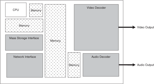
Figure 13.3 shows a vague, general-purpose SOC floor plan. Figure 13.4 shows a more specific diagram, that of a multimedia system, that represents many 21st-century SOCs. The multimedia system has function-specific blocks for processing audio and video and it has blocks for interfacing to a network and to mass-storage devices. This SOC floor plan could belong to a chip designed to be used in a mobile telephone handset, a personal multimedia player, a set-top box, or a number of other end products.
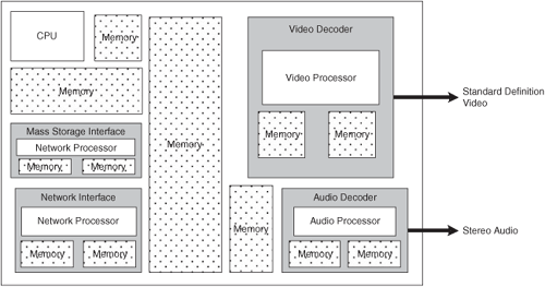
Each of the function-specific blocks in this multimedia SOC could contain one or more processors while some of the blocks may contain no processors at all, as shown in Figure 13.5. The SOC designers will determine how to design each block based on a number of factors including the availability of existing block designs and the amount of work to be performed in each block. In Figure 13.5, for example, one processor has been assigned the task of producing standard-resolution video and another processor has been assigned the task of generating stereo audio.
Figure 13.5. This floor plan for a multimedia SOC shows processor assignments for each function block.

Figure 13.6 shows a similar multimedia SOC designed for multimedia systems with higher performance than the SOC shown in Figure 13.5. The more powerful multimedia SOC produces high-definition video so the video block consists of two processors. This SOC also produces 5.1-channel audio, but one processor is still sufficient to generate all of the audio channels.
Figure 13.6. This floor plan for a high-performance multimedia SOC shows processor assignments for each function block.


