
Suppose you’ve been tracking and managing your project for some time now by using the Gantt Chart, the Resource Sheet, and other Project 2010 views. You can set up one of these views to contain exactly the fields of information you need and then print it to create a kind of interactive report. By printing views, you can share pertinent information with team members and stakeholders. You can include printed views in project status reports and in progress meetings.
To set up, preview, and print a view, follow these steps:
Open the view and arrange the data as you want it to appear when it’s printed.
Note
For more information about available views and arranging information in those views, see Chapter 4.
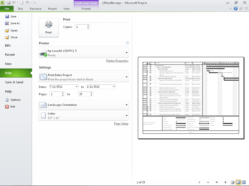
On the File tab, click Print.
The Print Backstage view appears, as shown in Figure 13-1. The Print Backstage view provides print options and a preview of the view as it will be printed.
In the lower-right area of the middle pane of the view, click Page Setup.
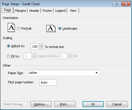
The Page Setup dialog box appears, as shown in Figure 13-2.
Specify the options you want for the printed view by using controls on the various tabs.
When you are finished, click OK to return to the Print Backstage view.
The changes you made are reflected in the preview pane on the right.
To zoom in the preview, click the area you want to zoom. To zoom it out again, click the preview again.
You can also zoom using the Actual Size, Full Page, and Multiple Pages buttons in the lower-right corner of the preview pane.
Use the arrow buttons in the lower-right corner of the preview pane to page through the view.
To make further adjustments to the page layout, click Page Setup in the middle pane again.
If you need to adjust the view itself, click one of the other tabs on the ribbon, such as Task or Format, to return to the editable view.
In the middle pane, specify any printing options, such as the number of copies, which printer is being used, which pages are being printed, and so on.
When you’re ready, in the upper-left corner of the middle pane, click Print.
Inside Out: The Print Backstage view provides scant preview flexibility
While the new Print Backstage view conveniently puts printer options and the print preview together in one view, this convenience limits flexibility when you are scrutinizing the view being printed. Some limitations are as follows:
You can only zoom between actual size (just a fragment), full size (small), and multiple pages (smaller still).
You can’t make the preview area larger by dragging the divider between the middle pane; the pane sizes are fixed.
You can’t see the preview in a full screen as in previous versions of Microsoft Project.
Because of this, your best options for closer examination are to just print out the view or save it as a PDF/XPS document.
To save it as a PDF/XPS document, on the File tab, click Save & Send. Under File Types, click Create PDF/XPS Document. In the right pane, click Create PDF/XPS. Browse to the location where you want to save the file, and then click OK. Make any necessary changes in the Document Export Options dialog box, and then click OK.
You can customize the zoom level and page through the PDF file to see the detail you want. If you need to make changes to the view or the print layout, click the appropriate tab and try again.
Note
For more information, see Saving a View as a PDF File.
The following list highlights key options available on the six tabs of the Page Setup dialog box, which controls how your view looks when printed. To display this dialog box, click File, Print, and then near the bottom of the middle pane of the Print Backstage view, click Page Setup.
Page tab. Specifies whether the view should be printed in portrait or landscape orientation and whether the view should be scaled up or down to fit on a page.
Margins tab. Specifies the size of each of the four margins and whether a border should be printed around the page.
Header tab. Specifies the content and location of header information. You can add the page number, current date and time, or the file name. You can also add a picture (such as a company or project logo) as part of your left, center, or right header. For example, click the Center tab, and then click Insert File Name to display the project file name at the center top of every page. You can also specify that a selected project field should be part of the header. You can enter your own text as well. Simply click the Left, Center, or Right tab, click in the text box, and then type the text you want.
Footer tab. Specifies the content and location of footer information. The same information available for headers is available for footers. For example, click the Left tab, and then click Insert Current Date to display the date in the lower-left corner of every page. The Preview box shows what your footer will look like.
Legend tab. Specifies the content and location of a view’s legend, which specifies what symbols or bars on the view represent. For example, in a print out of the Gantt Chart, the legend includes a key for the task bars, summary bars, deadlines, and milestone symbols. By default, the legend appears on the bottom two inches of every page and includes the project’s title and the current date. The options available for headers and footers are also available for legends, and you can also type your own information.
View tab. Specifies which elements you want printed on each page—for example, notes, blank pages, or sheet columns. The options available on this tab vary based on the view currently selected for printing.
Inside Out: Be careful when inserting the current date and time in a printed view
The Insert Current Date and Insert Current Time buttons take their information from your computer’s system clock. This date and time will change to reflect the date and time when you print the view. However, you might prefer to print a fixed date or time, perhaps one that specifies when the project was last updated, rather than last printed. In this case, in the Alignment area of the Page Setup dialog box, simply type the date or time in the Left, Center, or Right tab text box itself.
You might want to highlight certain items in a Gantt view before printing it out. New in Project 2010 is a set of drawing tools similar to those available in other Microsoft Office programs. The only place you can draw in is the chart area of a Gantt view. To mark up a schedule in a Gantt area, do the following:
On the Format tab, in the Drawings group, click Drawing, and then click the drawing tool you want.
You can choose from Arrow, Arc, Oval, Polygon, Rectangle, Line, and Text Box.
In the chart area of the Gantt view, drag from one point to another to draw the shape, or for polygons, to draw the first segment.
If you want to change the order in which elements appear—for example, to display a line in front of a filled rectangle—select the element you want to reorder. Click Format, Drawings, Drawing, and then click Bring To Front, Bring Forward, Send To Back, or Send Backward.