
i
i
i
i
i
i
i
i
450 18. Using Graphics Hardware
vertex( x3, y3, z3 );
vertex( x4, y4, z4 );
endTriangleStrip();
All vertices in this TriangleStrip have the same color and normal direction,
so these state parameters can be set prior to defining the vertices. This minimizes
both function call overhead and changes to the internal graphics state.
Many things can affect the performance of a graphics program, but one of the
potentially large contributors to performance (or lack thereof) is how your geome-
try is organized and whether it is stored in the memory cache of the graphics card.
In the pseudocode examples provided so far, geometry has been pushed onto the
graphics hardware in what is often called immediate mode rendering. As vertices
are defined, they are sent directly to the graphics hardware. The primary disad-
vantage of immediate mode rendering is that the geometry is sent to the graphics
hardware each iteration of your application. If your geometry is static (i.e., it
doesn’t change), then there is no real need to resend the data each time you re-
draw a frame. In these and other circumstances, it is more desirable to store the
geometry in the graphics card’s memory.
The graphics hardware in your computer is connected to the rest of the system
via a data bus, such as the PCI, AGP, or PCI-Express buses. When you send data
to the graphics hardware, it is sent by the CPU on your machine across one of
these buses, eventually being stored in the memory on your graphics hardware. If
you have very large triangle meshes representing complex geometry, passing all
this data across the bus can end up resulting in a large hit to performance. This
is especially true if the geometry is being rendered in immediate mode, as the
previous examples have illustrated.
There are various ways to organize geometry; some can help reduce the over-
all bandwidth needed for transmitting the geometry across the graphics bus. Some
possible organization approaches include:
• triangles. Triangles are specified with three vertices. A triangle mesh
created in this manner requires that each triangle in the mesh be defined
separately with many vertices potentially duplicated. For a triangle mesh
containing m triangles, 3m vertices will be sent to the graphics hardware.
• triangle strips. Triangles are organized in strips; the first three vertices
specify the first triangle in the strip and each additional vertex adds a tri-
angle. If you create a triangle mesh with m triangles organized as a single
triangle strip, you send three vertices to the graphics hardware for the first
triangle followed by a single vertex for each additional triangle in the strip
for a total of m +2vertices.
i
i
i
i
i
i
i
i
18.2. Describing Geometry for the Hardware 451
• indexed triangles. Triangle vertices are arranged as an array of vertices
with a separate array defining the triangles using indices into the vertex
array. Vertex arrays are sent to the graphics card with very few function
calls.
• indexed triangle strips. Similar to indexed triangles, triangle vertices are
stored in a vertex array. However, triangles are organized in strips with
theindexarraydefining the strip layout. This is the most compact of the
organizational structures for defining triangle meshes as it combines the
benefits of triangles strips with the compactness of vertex arrays.
Of the different organizational structures, the use of vertex arrays, either through
indexed triangles or indexed triangle strips, provides a good option for increasing
the performance of your application. The tight encapsulation of the organization
means that many fewer function calls need to be made as well. Once the vertices
and indices are stored in an array, only a few function calls need to be made to
transfer the data to the graphics hardware, whereas with the pseudocode examples
illustrated previously, a function is called for each vertex.
At this point, you may be wondering how the graphics state such as colors,
normals, or texture coordinates are defined when vertex arrays are used. In the
immediate-moderendering examples earlier in the chapter, interleavingthe graph-
ics state with the associated vertices is obvious based on the order of the function
calls. When vertex arrays are used, graphics state can either be interleaved in the
vertex array or specified in separate arrays that are passed to the graphics hard-
ware.
Even if the geometry is organized efficiently when it is sent to the graphics
hardware, you can achieve higher performance gains if you can store your geom-
etry in the graphics hardware’s memory for the duration of your application. A
somewhat unfortunate fact about current graphics hardware is that many of the
specifications describing the layout of the graphics hardware memory and cache
structure are often not widely publicized. Fortunately though, there are ways us-
ing graphics APIs that allow programmers to place geometry into the graphics
hardware memory resulting in applications that run faster.
Two commonly used methods to store geometry and graphics state in the
graphics hardware cache involve creating display lists or vertex buffer objects.
Display lists compile a compact list representation of the geometry and the
state associated with the geometry and store the list in the memory on the graphics
hardware. The benefits of display lists are that they are general purpose and good
at storing a static geometric representation plus associated graphics state on the
hardware. They do not work well at all for continuously changing geometry and
i
i
i
i
i
i
i
i
452 18. Using Graphics Hardware
graphics state, since the display list must be recompiled and then stored again
in the graphics hardware memory for every iteration in which the display list
changes.
displayID = createDisplayList();
color( r, g, b );
normal( nx, ny, nz );
beginTriangleStrip();
vertex( x0, y0, z0 );
vertex( x1, y1, z1 );
...
vertex( xN, yN, zN );
endTriangleStrip();
endDisplayList();
In the above example, a display list is created that contains the definition of a tri-
angle strip with its associated color and normal information. The commands be-
tween the createDisplayList and endDisplayList function calls pro-
vide the elements that define the display list. Display lists are most often created
during an initialization phase of an application. After the display list is created, it
is stored in the memory of the graphics hardware and can be referenced for later
use by the identifier assigned to the list.
// draw the display list created earlier
drawDisplayList(displayID);
When it is time to draw the contents of the display list, a single function call will
instruct the graphics hardware to access the memory indexed through the display
list identifier and display the contents.
Optimal Organization:
Much research effort has
gone into looking at ways
to optimize triangle meshes
for maximum performance
on graphics hardware. A
good place to start read-
ing if you want to delve fur-
ther into understanding how
triangle mesh organization
affects performance is the
SIGGRAPH 1999 paper on
the optimization of mesh lo-
cality (Hoppe, 1999).
A second method to store geometry on the graphics hardware for the duration
of your applicationis through vertex buffer objects (VBOs). VBOs are specialized
buffers that reside in high-performance memory on the graphics hardware and
store vertex arrays and associated graphics state. They can also provide a mapping
from your application to the memory on the graphics hardware to allow for fast
access and updating to the contents of the VBO.
The chief advantage of VBOs is that they provide a mapping into the graphics
hardware memory. With VBOs, geometry can be modified during an application
with a minimal loss of performance as compared with using immediate mode
rendering or display lists. This is extremely useful if portions of your geometry
change during each iteration of your application or if the indices used to organize
your geometry change.
VBOs are created in much the same way indexed triangles and indexed trian-
gle strips are built. A buffer object is first created on the graphics card to make
i
i
i
i
i
i
i
i
18.3. Processing Geometry into Pixels 453
room for the vertex array containing the vertices of the triangle mesh. Next, the
vertex array and index array are copied over to the graphics hardware. When it
is time to render the geometry, the vertex buffer object identifier can be used to
instruct the graphics hardware to draw your geometry. If you are already using
vertex arrays in your application, modifying your code to use VBOs should likely
require a minimal change.
18.3 Processing Geometry into Pixels
After the geometry has been placed in the graphics hardware memory, each ver-
tex must be lit as well as transformed into screen coordinates during the geometry
processing stage. In the fixed-functiongraphics pipeline illustrated in Figure 18.1,
vertices are transformed from a model coordinate system to a screen coordinate
frame of reference. This process and the matrices involved are described in Chap-
ters 7 and 8. The modelview and projection matrices needed for this transfor-
mation are defined using functions provided with the graphics API you decide to
use.
Lighting is calculated on a per-vertex basis. Depending on the global shading
parameters, the triangle face will either have a flat-shaded look or the face color
will be diffusely shaded (Gouraud shading) by linearly interpolating the color at
each triangle vertex across the face of the triangle. The latter method produces
a much smoother appearance. The color at each vertex is computed based on
the assigned material properties, the lights in the scene, and various lighting
parameters.
The lighting model in the fixed-function graphics pipeline is good for fast
lighting of vertices; we make a tradeoff for increased speed over accurate illu-
mination. As a result, Phong shaded surfaces are not supported with this fixed-
function framework.
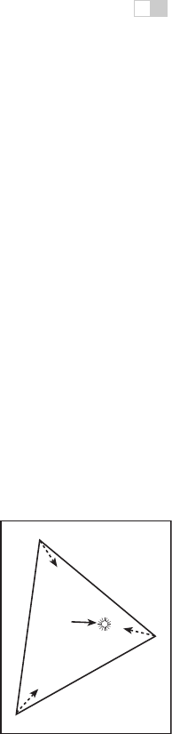
Figure 18.4. The distance
to the light source is small
relative to the size of the tri-
angle.
In particular, the diffuse shading algorithm built into the graphics hardware
often fails to compute the appropriate illumination since the lighting is only being
calculated at each vertex. For example, when the distance to the light source is
small, as compared with the size of the face being shaded, the illumination on
the face will be incorrect. Figure 18.4 illustrates this situation. The center of
the triangle will not be illuminated brightly despite being very close to the light
source, since the lighting on the vertices, which are far from the light source, are
used to interpolate the shading across the face.
With the fixed-function pipeline, this issue can only be remedied by increasing
the tessellation of the geometry. This solution works but is of limited use in real-

i
i
i
i
i
i
i
i
454 18. Using Graphics Hardware
time graphics as the added geometry required for more accurate illumination can
result in slower rendering.
However, with current hardware, the problem of obtaining better approxima-
tions for illumination can be solved without necessarily increasing the geometric
complexity of the objects. The solution involves replacing the fixed-function rou-
tines embedded within the graphics hardware with your own programs. These
small programs run on the graphics hardware and perform a part of the geometry
processing and pixel-processing stages of the graphics pipeline.
18.3.1 Programming the Pipeline
Fairly recent changes to the organization of consumer graphics hardware has gen-
erated a substantial buzz from game developers, graphics researchers, and many
others. It is quite likely that you have heard about GPU programming, graph-
ics hardware programming,orevenshader programming. These terms and the
changes in consumer hardware that have spawned them primarily have to do with
how the graphics hardware rendering pipeline can now be programmed.
Definition:
Fragment
is a
term that describes the in-
formation associated with
a pixel prior to being pro-
cessed by the graphics
hardware. This definition
includes much of the data
that might be used to cal-
culate the color of the pixel,
such as the pixel’s scene
depth, texture coordinates,
or stencil information.
Specifically, the changes have opened up two specific aspects of the graphics
hardware pipeline. Programmers now have the ability to modify how the hard-
ware processes vertices and shades pixels by writing vertex shaders and frag-
ment shaders (also sometimes referred to as vertex programs or fragment pro-
grams). Vertex shaders are programs that perform the vertex and normal trans-
formations, texture coordinate generation, and per-vertex lighting computations
normally computed in the geometry processing stage. Fragment shaders are pro-
grams that perform the computations in the pixel processing stage of the graphics
pipeline and determine exactly how each pixel is shaded, how textures are ap-
plied, and if a pixel should be drawn or not. These small shader programs are
sent to the graphics hardware from the user program (see Figure 18.5), but they
are executed on the graphics hardware. What this programmability means for
Geometry
Processing
Pixel
Processing
User
Program
primitives
2D screen
coordinates
vertex program
pixel shader
Figure 18.5. The programmable graphics hardware pipeline. The user program supplies
primitives, vertex programs, and fragment programs to the hardware.
..................Content has been hidden....................
You can't read the all page of ebook, please click here login for view all page.