
4.5 LIBRARIES AND DESIGN IDIOMS
In a sense design is idiomatic. Engineers can express designs in modes particular to a set of components at a specific level of design abstraction, for example, register transfer elements, or components particular to an implementation style for example, small-scale integration (SSI), MSI, and LSI TTL [TTL88]. If one adopts a bottom-up view of the world, then large designs are viewed as made up from aggregations of elementary components, usually gates. Since electronic logic by and large evolved from TTL elements, designs are perceived as compositions of TTL primitives. History has created a data base of collective design experience. This data base may be mined to create new designs from old experience, provided a set of primitive components exists in the new implementation style. This view has led the ASIC vendors to reproduce TTL libraries for customers’ use in designing (see Table 4–4). Alternatively, if one adopts a top-down view of the world, large designs are composed from generic high-level elements, such as counters, ALUs, and register files, whose specific features are defined in the design refinement process. This view of designing has led the ASIC suppliers to provide parameterized register-transfer (RT) and processor-memory switch (PMS) level component libraries, Table 4–4.
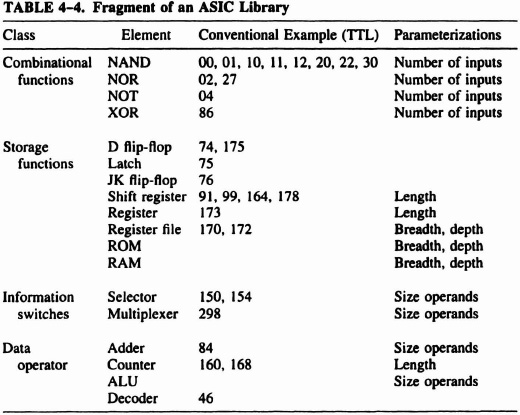
These hard and soft libraries are equally valid ways of collecting design experience and making it available to practicing engineers in tried and tested forms. Hard libraries try to maintain historical certainty in the encapsulation and functions of their elements. In a sense, they are fossilized design fragments that may limit the optimality of complete designs. Soft libraries can provide “made to measure” components for optimal designs at the expense of variations in performance for particular instantiations.
4.5.1 Parameterized Libraries
It is often very useful to think of library components as elements “sized” to a set of parameters: an n input gate, an n word by m bit stack, and so forth. In building a circuit the parameters are replaced by integer constants to suit the application. A simple way of satisfying this requirement would be to fill a library with all useful instantiations of a parameterized module and select a particular one by indexing from the parameter. This approach allows for more precise characterization of library elements at the expense of more storage. An alternative approach is to use the parameters in a program to generate the precise instance required. Two examples of this approach are described in the following subsections.
Parameterized Modules The requirement is to build a count “up-to-n” circuit. A generic counter and comparator, and constant generator, could be used to fit the requirement. The alternative approach would be to compose a counter from stages, each of which could test for a 0 or 1 depending on the position of these binary digits in the constant. By adding comparator gates, see Figure 4–13, to a basic toggle register we have the elements for building a count up-to-n circuit. The power of a programming language can be harnessed to assemble such a part. We need to build a vector of counter stages, each of which is conditionally defined. The iteration and conditional selection features of a programming language are well-suited to this task, provided there is a library of routines for describing and instantiating cells. The fragment of C code shown in Figure 4–14 shows this for assembling the “onestage” and “zerostage” of Figure 4–13. With upto = 5, the count-to-five circuit of Figure 4–15 would be generated.
Block Generators: The Configurable Logic ROM Generator With cellular FPGAs there is likely to be a simple way of implementing a two-level structure. In the case of CAL it is a configurable logic ROM. We will describe how it works by first discussing a simpler but less efficient scheme.
Simplified Version This version consists of an n-bit decoder, an “AND” plane, producing 2n-1 minterms feeding a special “OR” plane which uses two gate functions. As shown in Figure 4–16, the Algotronix CAL cell has four inputs, one per side. Any two can be selected as XI, X2 for the evaluation of an arbitrary Boolean function. The simplified CAL-ROM layout is shown in Figure 4–17. If the row is selected, the cell function depends on whether we require 0 or 1 output for this particular bit. On the other hand, if the row is not selected, we simply pass through the input received from the cell below, to take care of the case where the selected row is below. If the selected row is above, the output of this cell is of no consequence. Figure 4–18 gives the CAL cell configurations.
Compact Version The height of the array can be cut in half, and the decoder width reduced by one cell. The last input variable is introduced at the bottom of each OR-plane column, as shown in Figure 4–19, and each cell in the OR-plane computes a function of this variable and one of the minterms. If the row is selected, the input from below must be AO. If the row is not selected, it may either be below or above the selected row. In either case, it simply passes on the input received from below—either A0 or the output of the selected row. The cell function chosen depends on the value desired for A0 = 0 and A0 = 1, as shown in Table 4–5 and Figure 4–20. The program lisa automatically generates this arrangement for a multiple-output function given an arbitrary truth table.
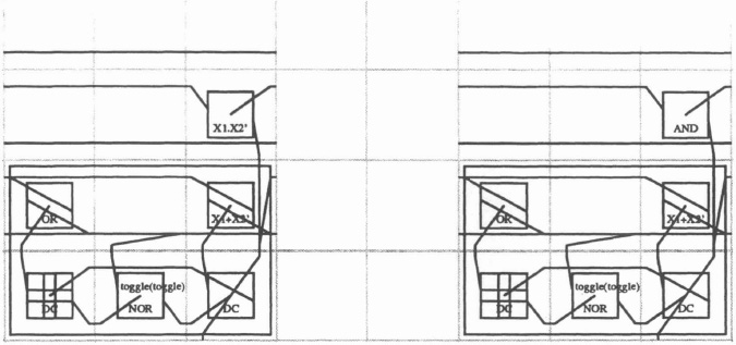
Figure 4–13. Stages for count-to-n circuit.
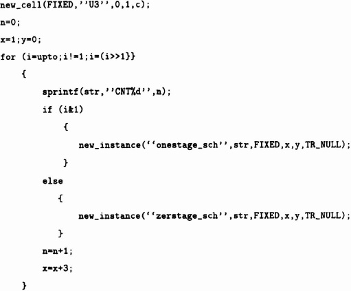
Figure 4–14. CAL operation.
Figure 4–21 shows the resulting layout of the CAL cell array, in which the 4 inputs appear at the lower left hand edge, q3, q2, q1, q0 and the outputs a,b,..., g at the upper edge. Figure 4–22 is a manually-composed alternative, with the inputs at the left and outputs at the right. Figure 4–23 is a layout for a Xilinx XC3020 design using the logic schematic given in Figure 4–4 as input.
Silicon Compilation The examples in this section of parameterized modules and generated blocks have shown physical synthesis from high level descriptions. The term “silicon compilation” [Gray79], has been applied to this process. In the case of the counter modules, the start point was a number of schematics for count cells, and a C program was designed to compose the cells to form the function. Because the start point for this process was a structural description, the C program and (software) library functions represent a structure compiler.
In the case of ROM block generator, the start point was a truth table, so the process was behavior compilation and the synthesis software represents a behavior compiler.
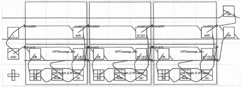
Figure 4–15. Count-to-five circuit.
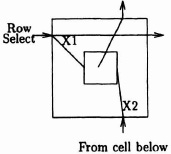
Figure 4–16. CAL cell. Note: the output is a function of the West (× 1) and South (×2) inputs.
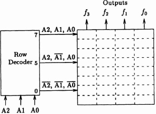
Figure 4–17. Simplified CAL-ROM layout.
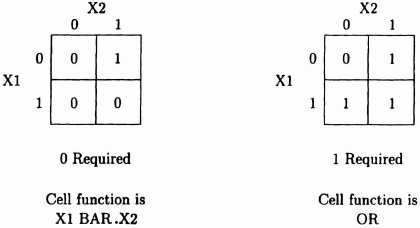
Figure 4–18. CAL cell configuration.
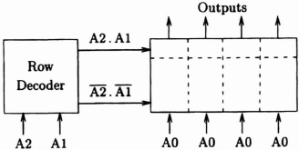
Figure 4–19. Compact CAL-ROM layout.
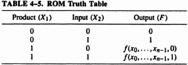
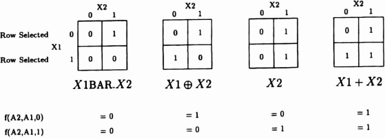
Figure 4–20. CAL cell options.
Both examples show the power of silicon compilation techniques in generating substantial design fragments quickly and with guaranteed structural integrity.
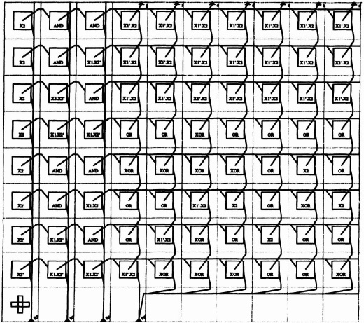
Figure 4–21. Physical designs for the display driver: ROM-based CAL design.