
5.4 RANDOM TESTING
For large systems, random testing is often a practical alternative to exhaustive, or case-by-case testing, and may be built into integrated circuits and systems.
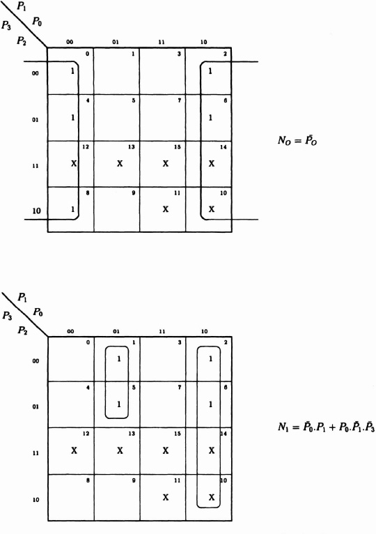
Figure 5–15. Equations for state machine: state encoding for decade counter, less-significant bits.
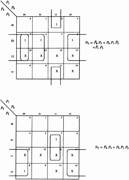
Figure 5–16. Equations for state machine: state encoding for decade counter more-significant bits.
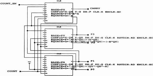
Figure 5–17. CLB entries for decade counter.

Figure 5–18. Configurable logic block array for 3-decade counter.
Input patterns may be readily generated with the LFSR method just described. Signature analysis is a technique for compressing the resulting output patterns into a short word whose final value indicates success or failure. While compression inevitably could allow some circuit failures to produce an identical signature, the risk is usually small.
We will take the 4-bit ripple adder described in Figure 5–4. Figure 5–21 shows the top-level schematic. Since there are eight input bits, along with carry-in, we will use a 9-bit pseudorandom number generator. To compress the four sum bits and the carry-out into 4 bits to be displayed on the demonstration board LEDs, we use a 4-bit signature analyzer.

Figure 5–19. CLB configuration.

Figure 5–20. Linear feedback shift register.
5.4.1 Signature Analyzer
The signature analyzer is an adaptation of the LFSR. At every clock cycle, a set of outputs from the ripple adder is loaded in parallel to an LFSR, with the feedback connections given earlier. These are XORed with the previous register contents as shown in Figure 5–22.
TABLE 5-2. LFSR Connections for Pseudorandom Sequence Generation
| Register Length | Feedback Connections |
| 2 | 0,1 |
| 3 | 0,2 |
| 4 | 0,3 |
| 5 | 1,4 |
| 6 | 0,5 |
| 7 | 2,6 |
| 8 | 1,2,3,7 |
| 9 | 3,8 |
Adapted from J. Mavor, M. Jack. and P. Denyer, Introduction to MOS LSI Design, Addison-Wesley. 1983, p. 118. © 1983, Addison-Wesley Publishing Co. Inc., reproduced with permission. Note: For a register length of 8, form the input by two EXCLUSIVE-OR gates feeding a third.
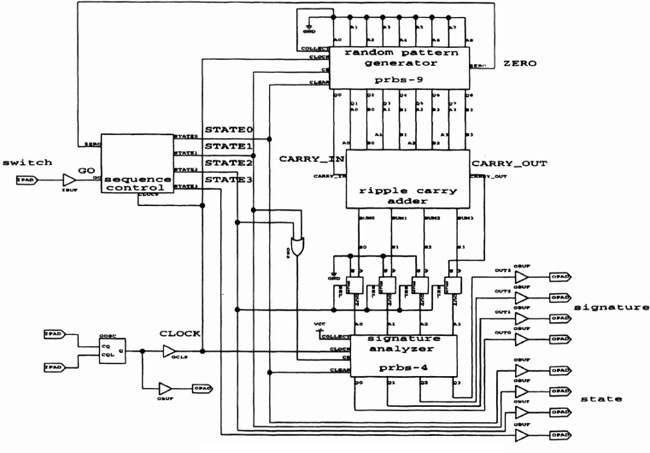
Figure 5–21. Top-level schematic of a parallel adder.

Figure 5–22. Signature analyzer.

Figure 5–23. State diagram
5.4.2 State Machine
As discussed in Chapter 2, state machines can be implemented in different ways. Encoded state machines may minimize the storage required, but at the expense of decoding logic, reducing speed. Here we use the one-hot method, that is, one bit per state. The four states are as follows:
- Initial state: wait for switch to be pressed
- Accumulate signature from four output bits in signature analyzer
- Accumulate carry-out bit in signature analyzer
- Display 4-bit signature on LEDs
Figure 5–23 shows the state diagram and Figure 5–24 shows the schematic. Note that State0 has inverting logic on both input and output, so that it automatically goes high when the FPGA is powered-up. Also, the State3 output is used to reset states 1 and 2 in the unlikely event of a logic state error, for example, if either bit was simultaneously asserted with State3.