
5.5 SYSTOLIC SORTER*
This example is included to suggest that FPGAs may provide novel ways of solving well-known problems. Sorting is required in many computer applications, particularly commercial ones. Here we look at a high-speed sorter, but one confined to miniscule amounts of data. It is described as systolic because it uses a repetitive block structure, and has a regular data flow. In general, each item to be sorted consists of a number of fields, of which one is selected as a key, on which to sort. For simplicity we regard the key as a nonnegative integer, and assume that we wish to sort items in ascending order of their keys. For simplicity, we concentrate on sorting the keys.
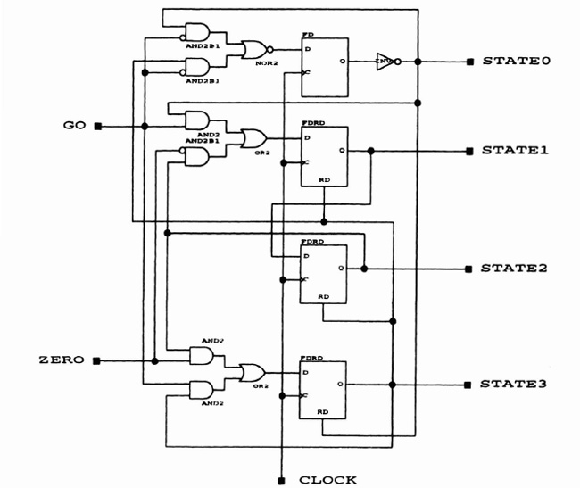
Figure 5–24. Schematic for state machine.
Knuth [Knuth73] distinguishes some basic sorting methods:
Sort by insertion: Find the correct place to insert an item in an already-ordered list
Sort by exchange: Consider pairs of keys, and swap them if out of order
Sort by enumeration: Find the smallest (or largest) key and remove the item to a new list. Repeat until the original list is empty.
The scheme described here is a combination of the first two methods. We assume that the items to be sorted arrive individually, so it makes sense to keep previous arrivals in order—we choose ascending. Borrowing a technique from full-custom VLSI design, we make up blocks of cells, and arrange for simple connections of data and control signals. The overall floorplan is shown in Figure 5–25. Each key is stored in a vertical column of one-bit blocks, with the least-significant bit at the top, and the most-significant bit adjacent to the control block at the bottom. New keys arrive at the left-hand side, and will “ripple” to the right, as they are compared with stored keys until they fall into the correct column. Each control block, of which there is one per key, simply uses the result of the arithmetic comparison made above:
if the stored key (S) is smaller than the one to its left (L),
    key L is passed to the cell on the right, i.e. bypassing S
otherwise, L must be stored in place of S, and S passed to the
    right
Figure 5–26 shows the data flow for the comparator cell, as implemented in Algotronix CAL logic. When all the keys have been submitted, the sorted list is returned by a series of left shifts, that is, so the smallest key emerges first.
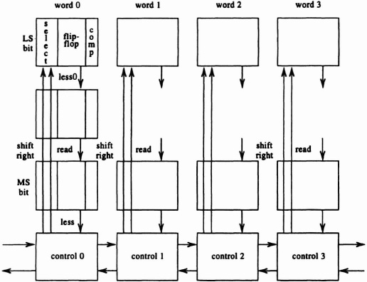
Figure 5–25. Systolic sorter.
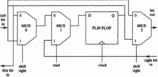
Figure 5–26. Sorter comparator cell—data flow.
In every column an arithmetic comparison is made, commencing with the less–significant bit at the top of the key. Each bit stage generates a signal “less,” which indicates that, based on the series of bits so far, the stored key is less than the one to its left. This result may change as the more significant bits are considered. The comparator logic is illustrated in Figure 5-27, and is described as follows:
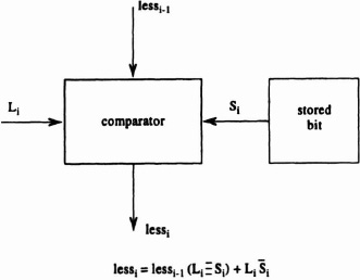
Figure 5–27. Sorter comparator cell. Comparison logic.
if the left-item bit and the stored bit are equivalent, pass
    on the “less” result from the Is comparator above.
otherwise, if the left-item bit is a 1, set “less” to 1 or if a
    0, then set “less” to 0.
It is implemented in the 1-bit comparator shown in Figure 5–28.
The control block is shown in Figure 5–29. Before sorting starts, the CLRb signal sets all the D flip-flops to 1, and as keys appear, Os are propagated through the control blocks. When the set of keys to be sorted has been entered, the results are retrieved in an ascending order by issuing a set of “read” instructions, which shift the contents of the control and key blocks left. Figure 5–30 shows an overall view of the sorter.