
i
i
i
i
i
i
i
i
578 22. Visual Perception
(a) (b)
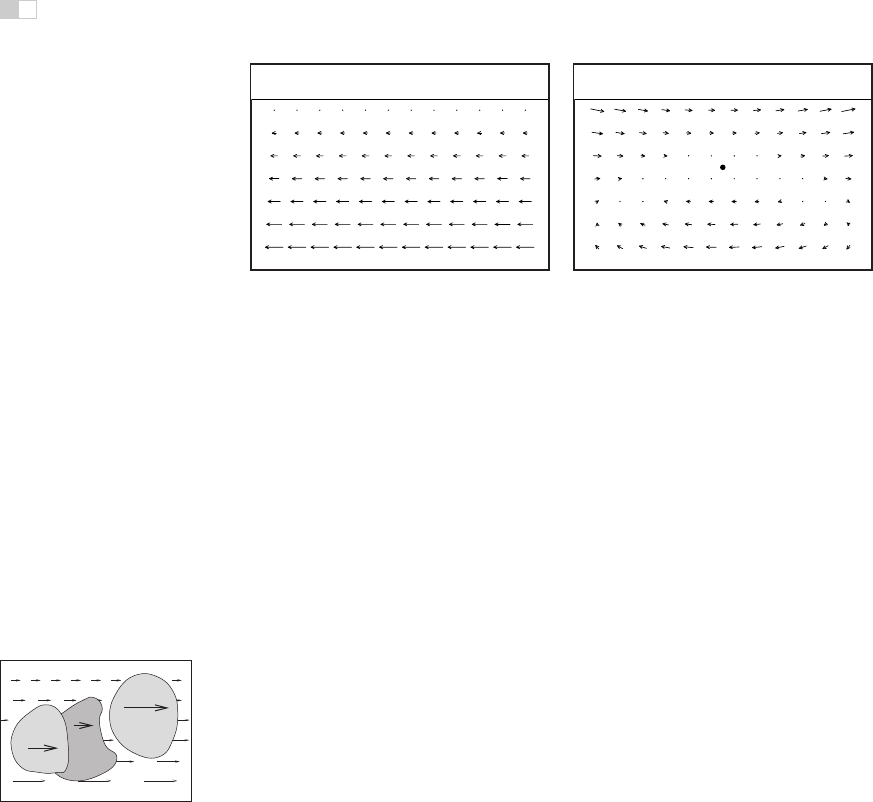
Figure 22.22. (a) Motion parallax generated by sideways movement to the right while
looking at an extended ground plane. (b) The same motion, with eye tracking of the fixation
point.
is referred to as motion parallax. For other surface points that project to reti-
nal locations near the fixation point, zero optic flow indicates a depth equivalent
to the fixation point; flow in the opposite direction to head translation indicates
nearer points, equivalent to crossed disparity; and flow in the same direction as
head translation indicates farther points, equivalent to uncrossed disparity (Fig-
ure 22.22). Motion parallax is a powerful cue to relative depth. In principle,
motion parallax can provide absolute depth information if the visual system has
access to information about the velocity of head motion. In practice, motion par-
allax appears at best to be a weak cue for absolute depth.
In addition to egocentric depth information due to motion parallax, visual
motion can also provide information about the three-dimensional shape of ob-
jects moving relative to the viewer. In the perception literature, this is known as
the kinetic depth effect. In computer vision, it is referred to as structure-from-
motion. The kinetic depth effect presumes that one component of object motion
is rotation in depth, meaning that there is a component of rotation around an axis
perpendicular to the line of sight.
A
B
C
Figure 22.23. Discon-
tinuities in optic flow sig-
nal surface boundaries. In
many cases, the sign of the
depth change (i.e., the or-
dinal depth) can be deter-
mined.
Optic flow can also provide information about the shape and location of sur-
face boundaries, as shown in Figure 22.23. Spatial discontinuities in optic flow
almost always either correspond to depth discontinuities or result from indepen-
dently moving objects. Simple comparisons of the magnitude of optic flow are
insufficient to determine the sign of depth changes, except in the special case of
a viewer moving through an otherwise static world. Even when independently
moving objects are present, however, the sign of the change in depth across sur-
face boundaries can often be determined by other means. Motion often changes
the portion of the more distant surface visible at surface boundaries. The appear-
ance (accretion) or disappearance (deletio n) of surface texture occurs because the
nearer, occluding surface progressively uncovers or covers portions of the more
i
i
i
i
i
i
i
i
22.3. Spatial Vision 579
distant, occluded surface. Comparisons of the motion of surface texture to either
side of a boundary can also be used to infer ordinal depth, even in the absence
of accretion or deletion of the texture. Discontinuities in optic flow and accre-
tion/deletion of surface texture are referred to as dynamic occlusion cues and are
another powerful source of visual information about the spatial structure of the
environment.
The speed that a viewer is traveling relative to points in the world cannot be
determined from visual motion alone (see Section 22.4.3). Despite this limitation,
it is possible to use visual information to determine the time it will take to reach a
visible point in the world even when speed cannot be determined. When velocity
is constant, time-to-contact (often referred to as time-to-collision)isgivenbythe
retinal size of an entity towards which the observer is moving, divided by the rate
at which that image size is increasing.
5
In the biological vision literature, this is
often called the τ function (Lee & Reddish, 1981). If distance information to the
structure in the world on which the time-to-collision estimate is based is available,
then this can be used to determine speed.
22.3.5 Pictorial Cues
An image can contain much information about the spatial structure of the world
from which it arose, even in the absence of binocular stereo or motion. As evi-
dence for this, note that the world still appears three-dimensional even if we close
one eye, hold our head stationary, and nothing moves in the environment. (As
discussed in Section 22.5, the situation is more complicated in the case of pho-
tographs and other displayed images.) There are three classes of such pictorial
depth cues. The best known of these involve linear perspective.Therearealso
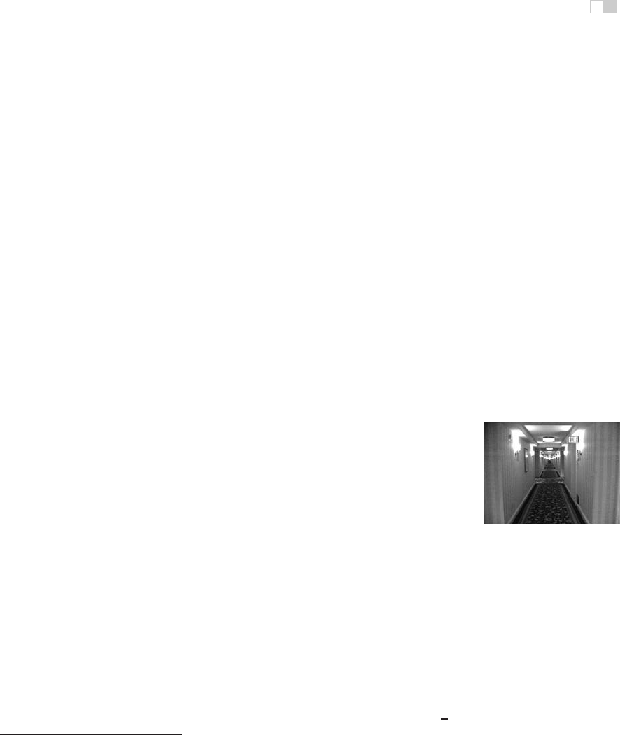
Figure 22.24. The
classical linear perspective
effects include object size
scaled by distance, the con-
vergence of parallel lines,
the ground plane extending
to a visible horizon, and po-
sition on the ground plane
relative to the horizon.
Im-
age courtesy Sam Pullara.
a number of occlusion cues that provide information about ordinal depth even in
the absence of perspective. Finally, illumination cues involving shading, shadows
and interreflections, and aerial perspective also provide visual information about
spatial layout.
The term linear perspective is often used to refer to properties of images in-
volving object size in the image scaled by distance, the convergence of parallel
lines, the ground plane extending to a visible horizon, and the relationship be-
tween the distance to objects on the ground plane and the image location of those
objects relative to the horizon (Figure 22.24). More formally, linear perspective
cues are those visual cues which exploit the fact that under perspective projection,
the image location onto which points in the world are projected is scaled by
1
z
,
5
The terms time-to-collision and time-to-contact are misleading, since contact will only occur if
the viewer’s trajectory actually passes through or near the entity under view.
i
i
i
i
i
i
i
i
580 22. Visual Perception
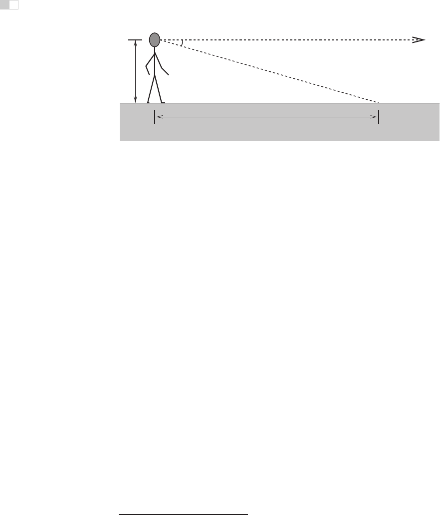
θ
h
d
d = h cot θ
Figure 22.25. Absolute distance to locations on the ground plane can be determined based
on declination angle from the horizon and eye height.
where z is the distance from the point of projection to the point in the environ-
ment. Direct consequences of this relationship are that points that are farther away
are projected to points closer to the center of the image (convergence of parallel
lines) and that the spacing between the image of points in the world decreases for
more distant world points (object size in the image is scaled by distance).
6
The
fact that the image of an infinite flat surface in the world ends at a finite horizon
is explained by examining the perspective projection equation as z →∞.
With the exception of size-related effects described in Section 22.4.2, most
pictorial depth cues involving linear perspective depend on objects of interest be-
ing in contact with a ground plane. In effect, these cues estimate not the distance
to the objects but, instead, the distance to the contact point on the ground plane.
Assuming observer and object are both on top of a horizontal ground plane, then
locations on the ground plane lower in the view will be close. Figure 22.25 illus-
trates this effect quantitatively. For a viewpoint h above the ground and an angle
of declination θ between the horizon and a point of interest on the ground, the
point in question is a distance d = h cot θ from the point at which the observer
is standing. The angle of declination provides relative depth information for arbi-
trary fixed viewpoints and can provide absolute depth when scaling by eye height
(h) is possible.
While the human visual system almost certainly makes use of angle of decli-
nation as a depth cue, the exact mechanisms used to acquire the needed informa-
tion are not clear. The angle θ could be obtained relative to either gravity or the
visible horizon. There is some evidence that both are used in human vision. Eye
height h could be based on posture, visually determined by looking at the ground
at one’s feet, or learned by experience and presumed to be constant. While a
6
The actual mathematics for analyzing the specifics of biological vision are different, since eyes
are not well approximated by the planar projection formulation used in computer graphics and most
other imaging applications.
i
i
i
i
i
i
i
i
22.3. Spatial Vision 581
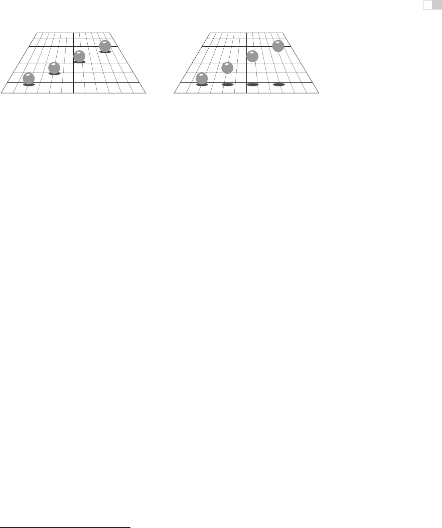
Figure 22.26. Shadows can indirectly function as a depth cue by associating the depth of
an object with a location on the ground plane (after Kersten et al. (1997)).
number of researchers have investigated this issue, if and how these values are
determined is not yet known with certainty.
Shadows provide a variety of types of information about three-dimensional
spatial layout. Attached shadows indicate that an object is in contact with another
surface, often consisting of the ground plane. Detached shadows indicate that an
object is close to some surface, but not in contact with that surface. Shadows can
serve as an indirect depth cue by causing an object to appear at the depth of the
location of the shadow on the ground plane (Yonas et al., 1978). When utilizing
this cue, the visual system seems to make the assumption that light is coming
from directly above (Figure 22.26).
Vision provides information about surface orientation as well as distance. It
is convenient to represent visually determined surface orientation in terms of tilt,
defined as the orientation in the image of the projection of the surface normal, and
slant,defined as the angle between the surface normal and the line of sight.
A visible surface horizon can be used to find the orientation of an (effectively
infinite) surface relative to the viewer. Determining tilt is straightforward, since
the tilt of the surface is the orientation of the visible horizon. Slant can be re-
covered as well, since the lines of sight from the eye point to the horizon define
a plane parallel to the surface. In many situations, either the surface horizon is
not visible or the surface is small enough that its far edge does not correspond
to an actual horizon. In such cases, visible texture can still be used to estimate
orientation.
In the context of perception, the term texture refers to visual patterns consist-
ing of sub-patterns replicated over a surface. The sub-patterns and their distri-
bution can be fixed and regular, as for a checkerboard, or consistent in a more
statistical sense, as in the view of a grassy field.
7
When a textured surface is
viewed from an oblique angle, the projected view of the texture is distorted rela-
tive to the actual markings on the surface. Two quite distinct types of distortions
occur (Knill, 1998), both affected by the amount of slant. The position and size
7
In computer graphics, the term texture has a different meaning, referring to any image that is
applied to a surface as part of the rendering process.
i
i
i
i
i
i
i
i
582 22. Visual Perception
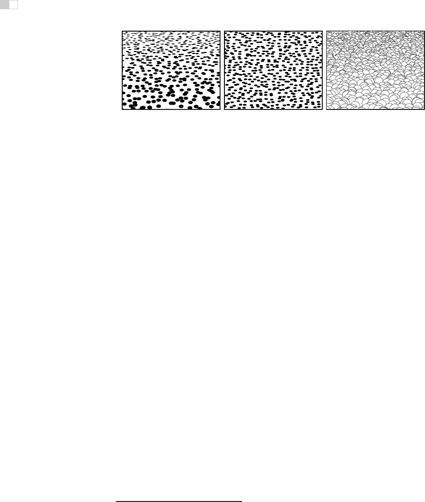
(a) (b) (c)
Figure 22.27. Texture cues for slant. (a) Near surface exhibiting compression and texture
gradient; (b) distant surface exhibiting only compression; (c) variability in appearance of near
surface with regular geometric variability.
of texture elements are subject to the linear perspective effects described above.
This produces a texture gradient (Gibson, 1950) due to both element size and
spacing decreasing with distance (Figure 22.27(a)). Both the image of individual
texture elements and the distribution of elements are foreshortened under oblique
viewing (Figure 22.27(b)). This produces a compression in the direction of tilt.
For example, an obliquely viewed circle appears as an ellipse, with the ratio of the
minor to major axes equal to the cosine of the slant. Note that foreshortening it-
self is not a result of linear perspective, though in practice both linear perspective
and foreshortening provide information about slant.
8
For texture gradients to serve as a cue to surface slant, the average size and
spacing of texture elements must be constant over the textured surface. If spa-
tial variability in size and spacing in the image is not due in its entirely to the
projection process, then attempts to invert the effects of projection will produce
incorrect inferences about surface orientation. Likewise, the foreshortening cue
fails if the shape of texture elements is not isotropic, since then asymmetric tex-
ture element image shapes would occur in situations not associated with oblique
viewing. These are examples of the assumptions often required in order for spa-
tial visual cues to be effective. Such assumptions are reasonable to the degree that
they reflect commonly occurring properties of the world.
Shading also provides information about surface shape (Figure 22.28). The
brightness of viewed points on a surface depends on the surface reflectance and
the orientation of the surface with respect to directional light sources and the
observation point. When the relative position of an object, viewing direction,
and illumination direction remain fixed, changes in brightness over a constant
reflectance surface are indications of changes in the orientation of the surface of
8
A third form of visual distortion occurs when surfaces with distinct 3D surface relief are viewed
obliquely (Leung & Malik, 1997), as shown in Figure 22.27(c). Nothing is currently know about if or
how this effect might be used by the human vision system to determine slant.
..................Content has been hidden....................
You can't read the all page of ebook, please click here login for view all page.