
138 ELASTOSTATICS
1-36
REFERENCE
2
O BE-QUADRATIC
VARIATION
AND QUARTER
POINTS
i-nnl
1 1 1 1 1 . , . .
uu
0 10 20 30 £0 50 60 70 8Q 90
ANGLE FROM X
r
AXIS
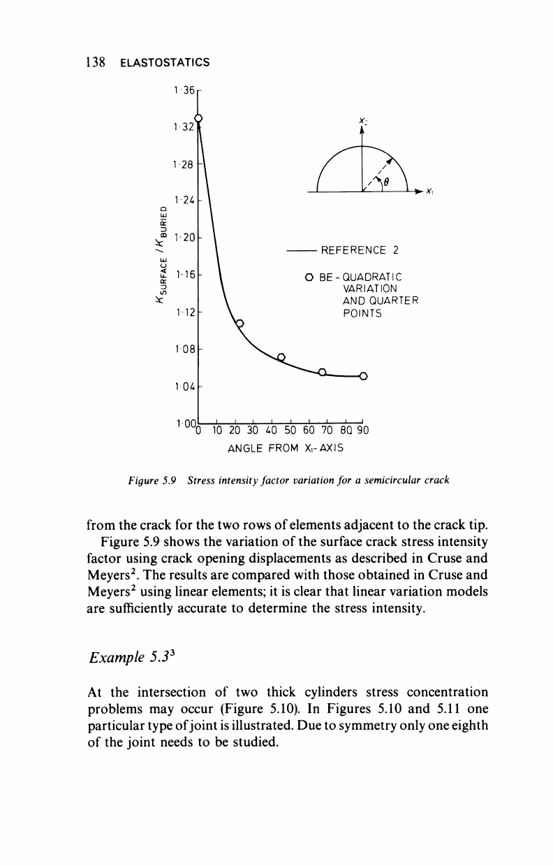
Figure 5.9 Stress intensity factor variation for a semicircular crack
from the crack for the two rows of elements adjacent to the crack tip.
Figure 5.9 shows the variation of the surface crack stress intensity
factor using crack opening displacements as described in Cruse and
Meyers
2
. The results are compared with those obtained in Cruse and
Meyers
2
using linear elements; it is clear that linear variation models
are sufficiently accurate to determine the stress intensity.
Example 5.3
3
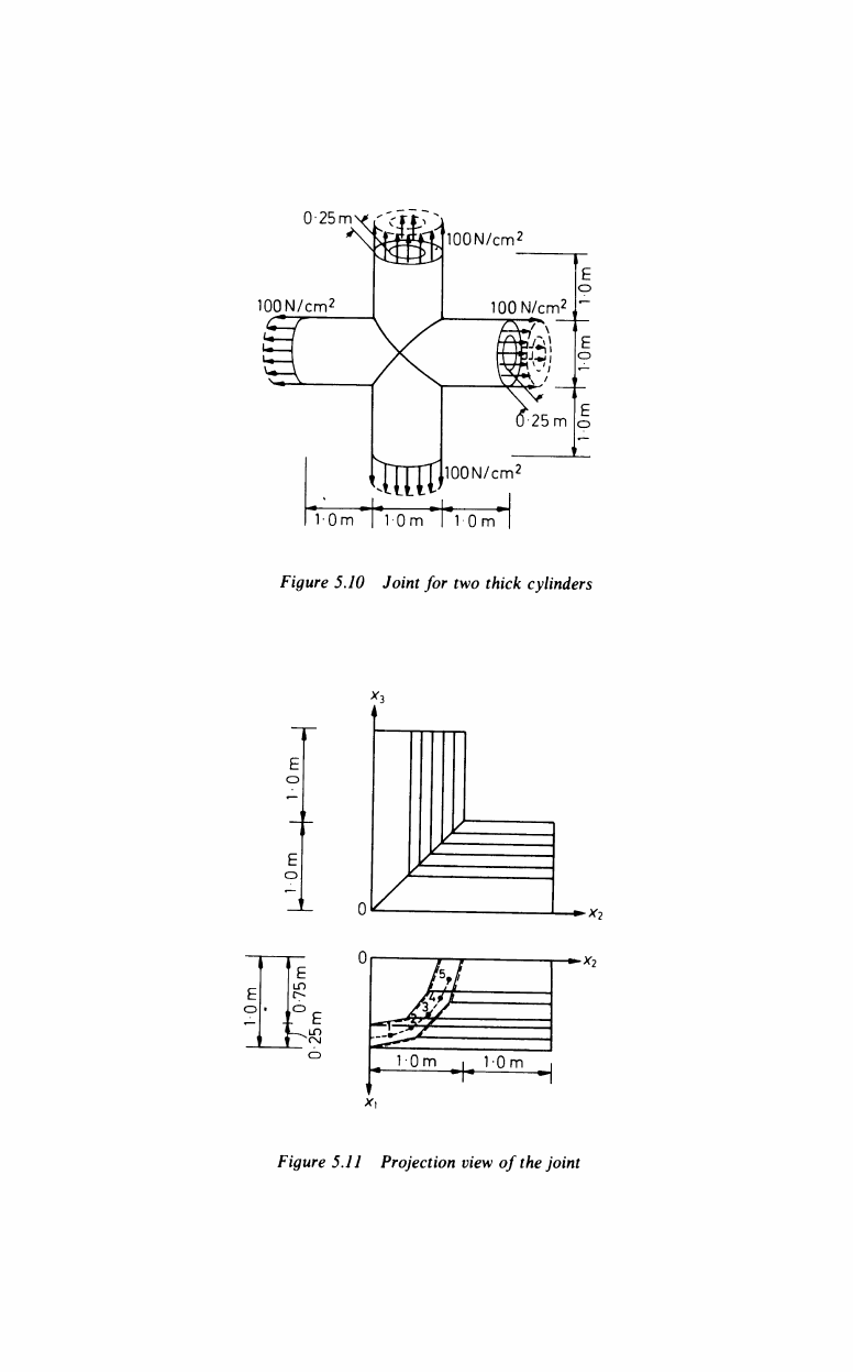
At the intersection of two thick cylinders stress concentration
problems may occur (Figure 5.10). In Figures 5.10 and 5.11 one
particular type of joint is illustrated. Due to symmetry only one eighth
of the joint needs to be studied.
0-25my,'
100N/cm
2
100N/cm
2
100N/cm
2
UfflD'
0-25
m L
lOON/cm
2
10m | 10m I 10m
Figure 5.10 Joint for two thick cylinders
E
*3
4
-*2
-*
2
E
K=
10m I 10m
Figure 5.11 Projection view of
the
joint
140 ELASTOSTATICS
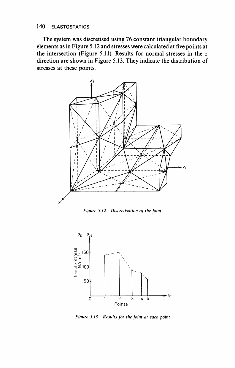
The system was discretised using 76 constant triangular boundary
elements as in Figure 5.12 and stresses were calculated at five points at
the intersection (Figure 5.11). Results for normal stresses in the z
direction are shown in Figure 5.13. They indicate the distribution of
stresses at these points.
Figure 5.12 Discretisation of the joint
σ
33=
σ
ΙΛ
£-150
i—CM
o
0 1 2 3 L 5
Points
Figure 5.13 Results for
the
joint at each point
►
v
..................Content has been hidden....................
You can't read the all page of ebook, please click here login for view all page.