
Scaling out refers to adding additional servers to increase performance, fault tolerance, or both. Scaling out the WFE role is done by using a load balancer. Load balancing works by pooling two or more servers together so that they appear to be, and function as, a single server. When a client request comes in, the load balancer intercepts the request and intelligently routes it to one of the available servers. (See Figure 5.9.) No special software is needed on the client because the load balancing is done on the back end. Load balancing is also transparent to users. Load balancing web servers is an active/active design, meaning that all servers are actively processing requests. This increases both performance and availability. It also simplifies server maintenance since you can pull a server (or node) out of the cluster when applying updates without bringing down the farm.
Figure 5.9: Two-node load-balancing cluster
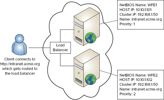
Each node in a load-balancing cluster is a self-contained server and not dependent on any other node. To simplify configuration and ensure a consistent experience for users, it is best to have identical hardware for each server node.
There are two main ways to implement load balancing to scale the WFE role:
- Microsoft’s Network Load Balancing (NLB) software built into Windows Server provides basic load balancing. This chapter focuses primarily on Microsoft’s NLB solution.
- Hardware or external load balancers run on dedicated devices. While more costly, they usually have more features and deliver better performance.
Configuring Windows-Based NLB
Windows Server has supported NLB for many versions and the software continues to improve. Although NLB will never surpass a hardware load balancer in total features or raw performance, it is a good solution for smaller-sized farms that have simple requirements and limited budgets.
When configuring NLB, it is best to have at least two network interface cards (NICs) in each server, whether physical or virtual. It is technically possible to use a single NIC, but performance can suffer. NICs can be teamed—just be sure to have at least two teams.
When configuring a Windows-based NLB, follow these four primary steps (as detailed in subsequent sections):
1. Configure the network interfaces for each WFE server.
2. Install the Windows NLB software on each WFE.
3. Create the NLB cluster, which adds the first node into the cluster.
4. Add additional nodes to the cluster.
NOTE Do not confuse an NLB cluster with Microsoft Cluster Service, which is used to cluster the operating system. These are completely different technologies that, unfortunately, use the same term.
Configuring WFE Servers
Before you create an NLB cluster and add servers to it, there are some preliminary steps you must complete to prepare the web servers:
1. Get SharePoint installed and have each server join the farm.
2. Since this is a WFE, make sure that the Microsoft SharePoint Foundation Web Application service is running. Other application services can be run, such as Search Query, but they are not managed by NLB. (SharePoint separately handles the load balancing of all application services.) If you choose to run application services on the WFE, each WFE server should run the same set of services.
3. Prepare the NICs. Each card plays a different role:
Host (Dedicated) Interface Used for normal network communication to other servers on the network. For instance, the WFE queries the database server. Ensure that the host NIC is configured properly with a static IP address.
Cluster Interface Intended exclusively for NLB traffic. The cluster NIC’s IP address and subnet mask will be set when you add the server to the cluster, so this can be left unconfigured for now.
TIP It is useful to rename your network interfaces to something more user-friendly. For example, you can name one host interface and the other cluster interface. Doing so makes the configuration easier and helps ensure you do not mix them up. You can rename the interfaces on the Network Connections screen found inside Control Panel.
Installing NLB
NLB software and drivers must be added to each WFE server before it can join the cluster. While NLB is built into Windows Server, it’s not usually installed by default. Here are the steps to install it:
1. Log in with an administrative account and start Server Manager (Start ⇒ All Programs ⇒ Administrative Tools ⇒ Server Manager).
2. In the navigation panel on the left, click Features.
3. In the right panel, click Add Features.
4. From the list, select Network Load Balancing and click Next.
5. Click Install and wait for the installation to complete. You normally do not have to reboot.
Creating the NLB Cluster
Clusters are created and managed using the Network Load Balancing Manager. This feature exists in both GUI and command-line form (nlb.exe). These steps walk you through creating the cluster by using the GUI:
1. Log in with an administrative account on the server that will become the first node in the cluster.
2. Start Network Load Balancing Manager (Start ⇒ All Programs ⇒ Administrative Tools ⇒ Network Load Balancing Manager).
3. Click Cluster ⇒ New.
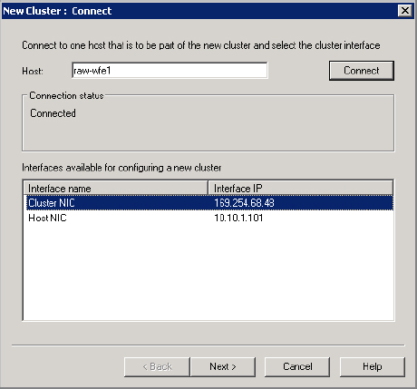
4. On the Connect page, enter the name of the server you just logged into and click Connect.
5. Under Interfaces Available For Configuring A New Cluster, choose the one that is designated for the cluster, as shown in Figure 5.10. Click Next. If DHCP is enabled on this interface, you will see a warning that it will be turned off.
Figure 5.10: Select the cluster interface
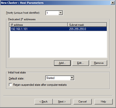
6. On the Host Parameters page, confirm that Priority is set to 1. The priority is a unique number placed on each server in the cluster. The server with the smallest number will receive all incoming requests if a port rule does not exist (you’ll create a port rule in a later step).
7. Enter a dedicated IP address for the cluster NIC, as shown in Figure 5.11. This address should be on the same subnet as the cluster address that is assigned in the next step. You need the address to enable communication from one NLB host to the other on the cluster subnet. Click Next.
Figure 5.11: Configuring host parameters
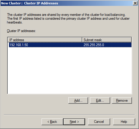
8. On the Cluster IP Addresses page, click Add.
9. Enter the cluster IP address you want to use. You can add multiple addresses for a single cluster. When you’re done, it should resemble Figure 5.12. Click Next.
Figure 5.12: Defining cluster IP addresses
10. On the Cluster Parameters page (Figure 5.13), in the Full Internet Name field, enter the fully qualified domain name for each IP address—for example, intranet.acme.org. This name should be resolvable using Domain Name System (DNS) and match the public URL for the SharePoint web application.
Figure 5.13: Setting cluster parameters
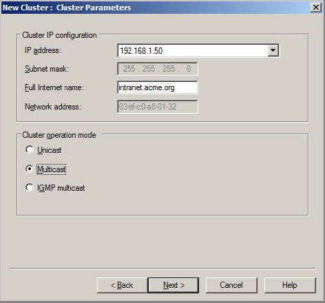
11. Choose the cluster operation mode. You have three choices: Unicast, Multicast, or Internet Group Management Protocol (IGMP) Multicast. Your best choice depends on your network infrastructure; here is a brief summary:
Unicast This mode is intended to be simple and is compatible with most routers and switches. It works by replacing the clustered NIC’s MAC (media access control) address. However, unicast can create a port-flooding problem with switches. This issue occurs when traffic directed to the cluster goes to all ports on the switch and not just the cluster hosts. This problem can be solved in many ways, but the easiest fix is to place a hub between the WFE servers and the switch. Unicast is not recommended if you’re using VMware or if you have only a single NIC. To use Unicast with Hyper-V in Windows Server 2008 R2, make sure that the cluster NIC is configured to allow spoofing of the MAC address.
Multicast This mode works by adding a multicast MAC address to the cluster NIC, retaining the card’s MAC address. Multicast is compatible with a single network card, but two are recommended for better performance. As with Unicast, port-flooding problems can result when you choose this setting.
IGMP Multicast This option solves the port-flooding problem by creating a multicast group membership, thereby filtering traffic to noncluster hosts on the same switch. To use this setting, your switch must support IGMP.
12. Click Next after you’ve configured the cluster operation mode.
13. In the Add/Edit Port Rule dialog box (Figure 5.14), enter the TCP/UDP ports that should be load balanced. By default, all ports are load balanced in a single rule. For SharePoint, this port should match the TCP port that is used for the SharePoint web application (typically 80 and/or 443).
Figure 5.14: Setting up a port rule
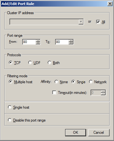
14. For Filtering mode, choose Multiple Host. This means that load-balanced routing is in effect.
15. For Affinity, Single is the recommended setting. This means that subsequent requests from the same client are directed to the same server. Single affinity is also called sticky sessions. Click OK when you’re finished configuring the port rule.
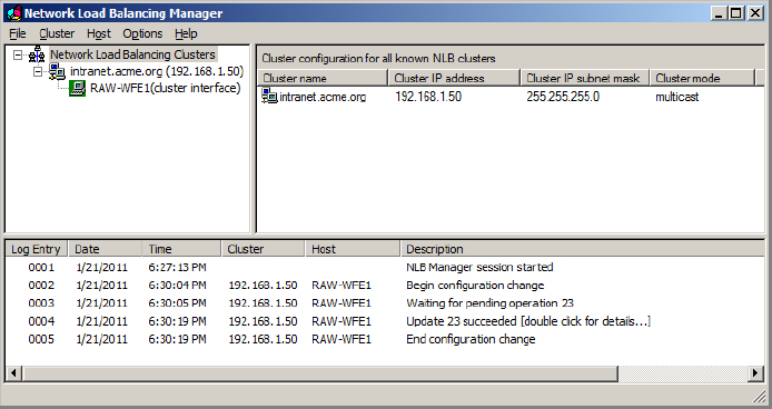
16. Click Finish to create the cluster and configure the first node. This process may take up to a minute to complete. The configuration is shown in the Network Load Balancing Manager log (Figure 5.15). When the process is finished, the status of the host should show as Converged when you select the cluster name (e.g., intranet.acme.org).
Figure 5.15: Cluster with one server node
17. Open Control Panel and, on the Network Connections screen, add a default gateway and DNS address to the cluster NIC. The NLB Manager does not add these settings. Now is also a good time to confirm that the IP address settings are correct.
Once the cluster is created, you should perform a variety of tests to ensure everything is working. Here are some combinations to try:
- Ping from an external client to the cluster IP address.
- Ping from an external client to the host IP address.
- Ping from the WFE server to hosts outside the cluster (e.g., the database server).
- Ping from the WFE server to the cluster IP address.
- Test the SharePoint web application to be sure it is still functioning.
Adding Nodes to the Cluster
Adding nodes to the cluster is much easier than creating a cluster. You can add nodes to the cluster from the first server, or you can run NLB Manager on the server to be added. Either way, here are the steps:
1. Start Network Load Balancing Manager.
2. Click Cluster ⇒ Connect To Existing and enter the server name that is the first node in the cluster (added in the previous section).
3. Right-click the cluster and select Add Host To Cluster.
4. Enter the server name of the new server you want to add. If you do not have administrative access to this server, you are prompted for credentials.
5. Select the cluster interface on the server and click Next. If DHCP is enabled on this interface, you will get a notice that it will be turned off.
6. Specify the priority for this node.
7. Enter a dedicated IP address for the cluster NIC. This should be on the same subnet as the cluster address but different from other dedicated IP addresses already assigned to other nodes. Click Next.
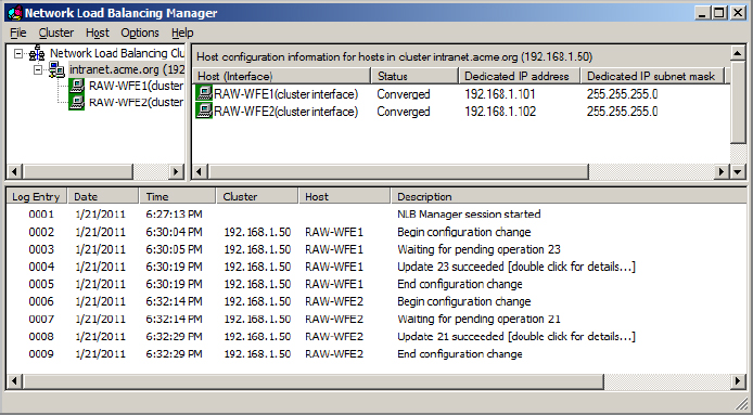
8. The existing port rules are shown. Click Finish to add the node. This process may take up to a minute to complete. When it finishes, the status of the host should show as Converged. See Figure 5.16.
Figure 5.16: Cluster with two server nodes
9. Manually add a default gateway and DNS address to the cluster NIC.
Once the host is added, perform the following tests:
- Ping from an external client to the cluster IP address.
- Ping from an external client to the host IP address.
- Ping from WFE server to hosts outside the cluster (e.g., the database server).
- Ping from the WFE server to the cluster IP address.
- Ping from the WFE server to the host IP address of other WFE servers.
- Test the SharePoint web application to be sure it is still functioning.
- For the real test, bring down each WFE one by one to be sure the NLB cluster is working correctly.
Using a Hardware-Based Load Balancer
For larger farms or those with more demanding performance requirements, a hardware-based load balancer may be a better solution than Microsoft’s built-in NLB. Many vendors provide solutions; F5 and Cisco are two of the leading vendors.
NOTE Microsoft’s Forefront Unified Access Gateway (UAG) can also do load balancing. For more information, see www.microsoft.com/uag.
Here are advantages of hardware load balancers compared to Microsoft NLB:
- More intelligent load balancing, in particular, for detecting application layer (HTTP) outages (when, for example, the server is still online, but IIS has stopped)
- Many more options when configuring load-balancing rules
- More scalable and better suited for heavily used applications
- Can often be combined with web accelerator technologies to further improve performance
There are also some disadvantages:
- More costly solution
- May be more complex to configure, requiring specialized knowledge of the product
- Single point of failure if the load balancer doesn’t have redundancy
Running Central Administration on Multiple Servers
As a general recommendation, you should run the Central Administration Web Application on more than one server in your farm. This approach gives you added protection in case the primary server is down and you need to do essential maintenance. To add Central Administration to a second server, follow these steps:
1. Log into the server using the domain installer account.
2. Start the Configuration Wizard (Start ⇒ All Programs ⇒ Microsoft SharePoint 2010 Products ⇒ SharePoint 2010 Products Configuration Wizard.
3. Click Next and acknowledge the warning.
4. When prompted, do not disconnect the server from the farm. Click Next.
5. On the Completing page, click the Advanced Settings button.
6. Select the option “Use this machine to host the web site.”
7. Click OK.
8. Click Next to apply the changes.
At this point, Central Administration has been configured on this new server. However, there are two related problems. If you launch Central Administration from the Start menu, it will always go to the first (original) server. SharePoint will also redirect you to the first server if you try to run Central Administration directly by using the URL of the second server in the browser.
To fix the first problem when running Central Administration from the Start menu, follow these steps:
1. Log into the second server and start Registry Editor (Start ⇒ Run, and type regedit).
2. Navigate to the following key: HKEY_LOCAL_MACHINE ⇒ Software ⇒ Microsoft ⇒ Shared Tools ⇒ Web Server Extensions ⇒ 14.0 ⇒ WSS.
3. Edit the CentralAdministrationURL value and replace it with the http://ServerName:Port address of the second server (for example, http://wfe2:11111).
To fix the second problem where requests are automatically redirected to the first server, you need to edit the public URLs for the Central Administration Web Application. Here are the steps:
1. Start Central Administration.
2. Click System Settings, and then choose Configure Alternate Access Mappings.
3. Under Alternate Access Mapping Collection, select the Central Administration Web Application.
4. Click Edit Public URLs.
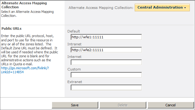
5. For any of the other zones, enter the http://ServerName:Port address. Your screen should resemble Figure 5.17.
Figure 5.17: Adding a public URL for Central Administration
WARNING Adjusting the alternate access mappings in this way will not work if you are using Kerberos authentication on the Central Administration Web Application. See “SharePoint Central Administration: High Availability, Load Balancing, Security & General Recommendations” at www.harbar.net/articles/spca.aspx for a workaround and more details on configuring Central Administration on multiple servers.