
Build the base of the robot with four wheels by creating a file in the chapter6_tutorials/robot_description/urdf folder with the name mobile_robot.urdf, and add the following code:
<?xml version="1.0"?>
<robot name="mobile">
   <link name="base_link">
         <visual>
               <geometry>
                     <box size="0.2 .3 .1"/>
               </geometry>
               <origin rpy="0 0 0" xyz="0 0 0.05"/>
               <material name="yellow">
                     <color rgba="255 255 0 1"/>
               </material>
         </visual>
         <collision>
               <geometry>
                     <box size="0.2 .3 0.1"/>
               </geometry>
         </collision>
         <inertial>
               <mass value="100"/>
               <inertia ixx="1.0" ixy="0.0" ixz="0.0" iyy="1.0" iyz="0.0" izz="1.0"/>
         </inertial>
   </link>
   <link name="wheel_1">
         <visual>
               <geometry>
                     <cylinder length="0.05" radius="0.05"/>
               </geometry>
               <origin rpy="0 1.5 0" xyz="0.1 0.1 0"/>
               <material name="black">
                     <color rgba="0 0 0 1"/>
               </material>
         </visual>
         <collision>
               <geometry>
                     <cylinder length="0.05" radius="0.05"/>
               </geometry>
         </collision>
         <inertial>
               <mass value="10"/>
               <inertia ixx="1.0" ixy="0.0" ixz="0.0" iyy="1.0" iyz="0.0" izz="1.0"/>
         </inertial>
   </link>
   <link name="wheel_2">
         <visual>
               <geometry>
                     <cylinder length="0.05" radius="0.05"/>
               </geometry>
               <origin rpy="0 1.5 0" xyz="-0.1 0.1 0"/>
               <material name="black"/>
         </visual>
         <collision>
               <geometry>
                     <cylinder length="0.05" radius="0.05"/>
               </geometry>
         </collision>
         <inertial>
               <mass value="10"/>
               <inertia ixx="1.0" ixy="0.0" ixz="0.0" iyy="1.0" iyz="0.0" izz="1.0"/>
         </inertial>
   </link>
   <link name="wheel_3">
         <visual>
               <geometry>
                     <cylinder length="0.05" radius="0.05"/>
               </geometry>
               <origin rpy="0 1.5 0" xyz="0.1 -0.1 0"/>
               <material name="black"/>
         </visual>
         <collision>
               <geometry>
                     <cylinder length="0.05" radius="0.05"/>
               </geometry>
         </collision>
         <inertial>
               <mass value="10"/>
               <inertia ixx="1.0" ixy="0.0" ixz="0.0" iyy="1.0" iyz="0.0" izz="1.0"/>
         </inertial>
   </link>
   <link name="wheel_4">
         <visual>
               <geometry>
                     <cylinder length="0.05" radius="0.05"/>
               </geometry>
               <origin rpy="0 1.5 0" xyz="-0.1 -0.1 0"/>
               <material name="black"/>
         </visual>
         <collision>
               <geometry>
                     <cylinder length="0.05" radius="0.05"/>
               </geometry>
         </collision>
         <inertial>
               <mass value="10"/>
               <inertia ixx="1.0" ixy="0.0" ixz="0.0" iyy="1.0" iyz="0.0" izz="1.0"/>
         </inertial>
   </link>
   <joint name="base_to_wheel1" type="continuous">
         <parent link="base_link"/>
         <child link="wheel_1"/>
         <origin xyz="0 0 0"/>
   </joint>
   <joint name="base_to_wheel2" type="continuous">
         <parent link="base_link"/>
         <child link="wheel_2"/>
         <origin xyz="0 0 0"/>
   </joint>
   <joint name="base_to_wheel3" type="continuous">
         <parent link="base_link"/>
         <child link="wheel_3"/>
         <origin xyz="0 0 0"/>
   </joint>
   <joint name="base_to_wheel4" type="continuous">
         <parent link="base_link"/>
         <child link="wheel_4"/>
         <origin xyz="0 0 0"/>
   </joint>
</robot>
The preceding URDF code has an XML file format, where indentation is not necessary, but recommended. We can use a reasonably advanced editor with the required plugins or configuration such as an appropriate .vimrc file in vim or the atom editor by default:
- URDF file format:
- You may have noticed that in the code, there are two primary elements that define the geometry of a robot, links, and joints, where the first link has the name base_link, which must be unique to the file:
<link name="base_link">
         <visual>
               <geometry>
                     <box size="0.2 .3 .1"/>
               </geometry>
               <origin rpy="0 0 0" xyz="0 0 0.05"/>
               <material name="yellow">
                     <color rgba="255 255 0 1"/>
               </material>
         </visual>
         ...
</link>
-
- The visual element in the preceding code defines what will be displayed on the simulator, where we can define the geometry—cylinder, box, sphere, mesh, the material—color, texture, and the origin. Then, we have to code the joint, as follows:
<joint name="base_to_wheel1" type="continuous">
         <parent link="base_link"/>
         <child link="wheel_1"/>
         <origin xyz="0 0 0"/>
</joint>
-
- Similarly, in the joint field which must be unique as well, define the type of joint, which is going to be fixed, revolute, continuous, floating, or planar, along with the parent and child relationship between the joints. Here, base_link is the unique parent of wheel_1.
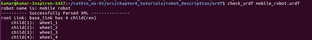
- Moreover, we can check the correctness of the syntax in the previously created URDF file by using the check_urdf command tool:
$ check_urdf mobile_robot.urdf
-
- The expected output is shown in the following screenshot:
-
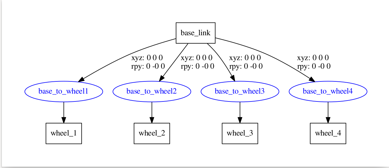
- We can view the architecture diagram graphically using the urdf_to_graphiz command tool:
$ urdf_to_graphiz mobile_robot.urdf
-
- This command tool will generate two files, which are mobile.pdf and mobile.gv. We can open the file with evince as follows:
$ evince mobile.pdf
The following shows the architecture diagram received as output:
- 3D Model on Rviz:
- We have discussed how to create a 3D model robot. From here, we can view the 3D model simulation using rviz. We will create the simulation.launch file in the robot_description/launch folder and add the following code. Alternatively, we can get the file from GitHub (https://github.com/kbipin/Robot-Operating-System-Cookbook):
<?xml version="1.0"?>
<launch>
   <arg name="model" />
   <arg name="gui" default="False" />
   <param name="robot_description" textfile="$(arg model)" />
   <param name="use_gui" value="$(arg gui)"/>
   <node name="joint_state_publisher" pkg="joint_state_publisher" type="joint_state_publisher" ></node>
   <node name="robot_state_publisher" pkg="robot_state_publisher" type="state_publisher" />
   <node name="rviz" pkg="rviz" type="rviz" args="-d $(find robot_description)/robot.rviz" />
</launch>
-
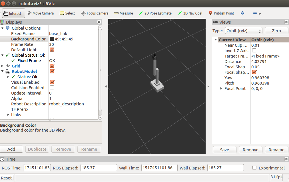
- Then, we can launch the robot model using the following command:
$ roslaunch robot_description simulation.launch model:="'rospack find robot_description'/urdf/mobile_robot.urdf"
-
- Thereupon, we can view the 3D model of the mobile robot, as shown in the following screenshot:

-
- Similarly, we will design a 3D model of a robot manipulator, which will have a base and an articulated arm with a gripper. We can get the complete model from the chapter6_tutorials/robot_description/urdf/arm_robot.urdf file in GitHub. Then, we can launch the robot model by using the following command:
$ roslaunch robot_description display.launch model:="'rospack find robot1_description'/urdf/arm_robot.urdf"
-
- We can view the 3D model of the robot manipulator, as shown in the following screenshot:
- Meshes with the 3D model:
- We would like to have a realistic look for our model or a more detailed design, rather than basic geometric blocks. This is possible using meshes, which might be custom generated or meshes of other models that are available from the community.
- In the case of the 3D model of the robot manipulator, which we discussed previously, we will use PR2's gripper. The following code snippet describes how to use it:
<link name="left_gripper">
         <visual>
               <origin rpy="0 0 0" xyz="0 0 0"/>
               <geometry>
                     <mesh filename="package://urdf_tutorial/meshes/l_finger.dae"/>
               </geometry>
         </visual>
         <collision>
               <geometry>
                     <box size="0.1 .1 .1"/>
               </geometry>
         </collision>
         <inertial>
               <mass value="1"/>
               <inertia ixx="1.0" ixy="0.0" ixz="0.0" iyy="1.0" iyz="0.0" izz="1.0"/>
         </inertial>
</link>
-
- However, this resembles the sample link that we used before, but in the geometry section, we added the mesh. Consequently, you can see the result in the following diagram:

- Control and motion:
- The 3D model of the robot can have control and motion according to the joints described in the URDF file. The most used type of joint is the revolute joint, in the case of the arm robot.
- You may have noticed it being used on arm_1_to_arm_base in the following code:
<joint name="arm_1_to_arm_base" type="revolute">
         <parent link="arm_base"/>
         <child link="arm_1"/>
         <axis xyz="1 0 0"/>
         <origin xyz="0 0 0.15"/>
         <limit effort ="1000.0" lower="-1.0" upper="1.0" velocity="0.5"/>
</joint>
-
- The revolute joints have strict limits, which are fixed using the <limit effort ="1000.0" lower="-1.0" upper="1.0" velocity="0.5"/> line in the URDF file. We can also select the axis of rotation using <axis xyz="1 0 0">. We can use the <limit> tag to define the set of attributes—effort defines the maximum force supported by the joint, lower is used to assign a lower limit, for example, radian for revolute joints and meters for prismatic joints, upper is used for the upper limit, and velocity is used for enforcing the maximum joint velocity.
- We can confirm the axis and limits of the joints' attributes by running rviz with the join_state_publisher graphically, as follows:
$ roslaunch robot_description simulation.launch model:="'rospack find robot_description'/urdf/arm_robot.urdf" gui:=true
-
- The GUI will pop up, as shown in the following screenshot:

-
- Similarly, the mobile robot model uses a continuous-type joint, as shown in the following code snippet:
<joint name="base_to_wheel1" type="continuous">
         <parent link="base_link"/>
         <child link="wheel_1"/>
         <origin xyz="0 0 0"/>
</joint>
- Physical properties:
- To simulate the 3D robot model in Gazebo or any other simulation software which has a physics engine, the physical and collision properties of the model must be defined in the URDF files. In other words, the model must define its geometry to calculate the possible collisions and the weight in order to measure its inertia.
- It is essential that all links defined in the model file have these parameters, otherwise the robot model will not be simulated by the physics engine. However, calculating the collisions among meshes is computationally complex, and therefore the simplified geometry of a mesh model can be used rather than the actual mesh.
- In the following code, you may notice the physical and collision properties of link with the name wheel_1 in mobile_robot.urdf for the mobile robot:
<link name="wheel_1">
         <visual>
               <geometry>
                     <cylinder length="0.05" radius="0.05"/>
               </geometry>
               <origin rpy="0 1.5 0" xyz="0.1 0.1 0"/>
               <material name="black">
                     <color rgba="0 0 0 1"/>
               </material>
         </visual>
         <collision>
               <geometry>
                     <cylinder length="0.05" radius="0.05"/>
               </geometry>
         </collision>
         <inertial>
               <mass value="10"/>
               <inertia ixx="1.0" ixy="0.0" ixz="0.0" iyy="1.0" iyz="0.0" izz="1.0"/>
         </inertial>
</link>
Similarly, collision and inertial elements are defined for all the links in both the mobile and arm robot, as discussed previously, since if we do not do so, Gazebo will not simulate the model.
We can find a complete file with all the parameters in mobile_robot.urdf and arm_robot.urdf at robot_description/urdf/ at GitHub (https://github.com/kbipin/Robot-Operating-System-Cookbook).