
However, in the real MAVs, generally, there is no direct odometry sensor, such as has been used in the previous subsection. Rather, there is a broad variety of sensors, such as GPS and magnetometer, cameras, or lasers to do SLAM, or external tracking systems such as motion capture setup that provide a full six degrees of freedom (6DoF) for pose. In this section, we will discuss how to use MSF packages to get the full state from a pose sensor and the IMU.
We will run the example that needs the rotors_simulator_demos package that was downloaded in the previous subsection. The following command will start all the required ROS nodes:
$ roslaunch rotors_simulator_demos mav_hovering_example_msf.launch
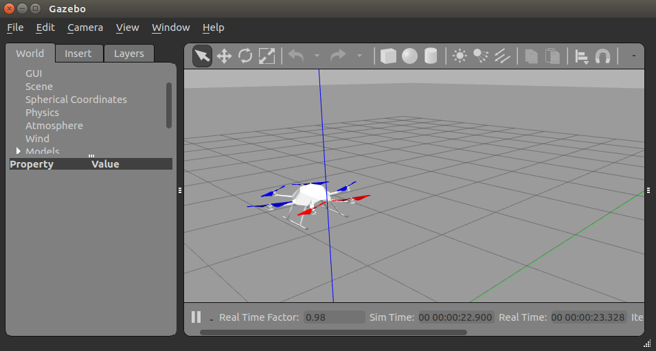
We can observe, in the following screenshot, that this time the MAV is not as stable as in the previous example, which had a small offset at the beginning. Here, wobbling comes from the simulated noise on the pose sensor and the offset from the IMU biases. Nevertheless, after a while the offset will disappear, because the Extended Kalman Filter (EKF) estimates the biases correctly:
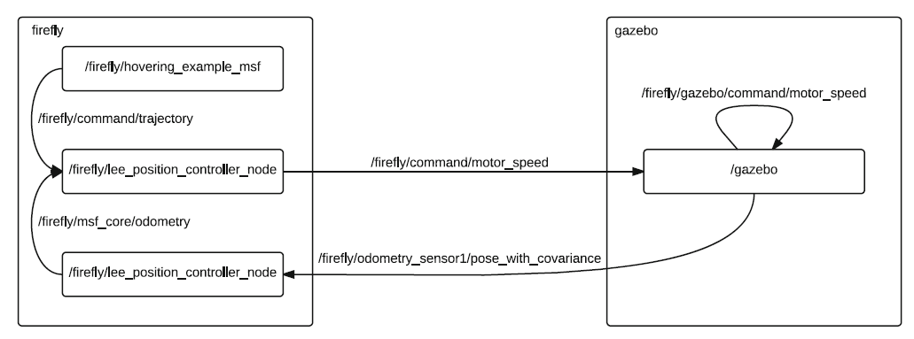
Here, looking at the re-drawn rqt_graph in the following diagram, we can see that an additional node is started. The MSF pose_sensor and the controller node now subscribe to the odometry topic from the MSF, instead of the odometry from Gazebo:
As discussed in the previous subsection, the following command can be used to move the MAV:
$ rosrun rotors_gazebo waypoint_publisher 5 0 1 0 __ns:=firefly
The MSF package performs the state estimation based on IMU measurements, which can use any predefined available sensor combinations, and we use pose_sensor in this example, where the parameters are loaded from the msf_simulator.yaml located in the rotors_simulator_demos/resources folder.