We have learned how to simulate the physics of the robot and its motion, and we can also simulate the sensors in Gazebo.
Usually, in order to simulate the sensors, we need to implement their physical behavior. In other words, it is required that we design the mathematical model of the sensors.
In this section, we will discuss how to add a camera and a laser sensor to the mobile robot model we designed previously. Since these sensors are new elements of the robot model, first of all, we have to decide where to install them. In the preceding screenshot, you may have noticed a new 3D gadget that looks like a Hokuyo laser, and a red cube which will be the camera in Gazebo.
We will use the laser simulation plugin from the gazebo_ros_demos package. Accordingly, we have to include the following lines in the robot_gazebo.xacro file to add the 3D model of a Hokuyo laser to the mobile robot:
<link name="hokuyo_link">
    <collision>
      <origin xyz="0 0 0" rpy="0 0 0"/>
      <geometry>
   <box size="0.1 0.1 0.1"/>
      </geometry>
    </collision>
    <visual>
      <origin xyz="0 0 0" rpy="0 0 0"/>
      <geometry>
        <mesh filename="package://robot_description/meshes/hokuyo.dae"/>
      </geometry>
    </visual>
    <inertial>
      <mass value="1e-5" />
      <origin xyz="0 0 0" rpy="0 0 0"/>
      <inertia ixx="1e-6" ixy="0" ixz="0" iyy="1e-6" iyz="0" izz="1e-6" />
    </inertial>
</link>
Furthermore, we will add the libgazebo_ros_laser.so plugin to the robot.gazebo file, which will simulate the behavior of a Hokuyo range laser in Gazebo. Similarly, we will add the libgazebo_ros_camera.so plugin there to simulate the camera. We can refer to the source code of robot.gazebo in the chapter6_tutorials packages at GitHub (https://github.com/kbipin/Robot-Operating-System-Cookbook):
<!-- hokuyo -->
  <gazebo reference="hokuyo_link">
    <sensor type="ray" name="head_hokuyo_sensor">
      <pose>0 0 0 0 0 0</pose>
      <visualize>false</visualize>
      <update_rate>40</update_rate>
      <ray>
        <scan>
          <horizontal>
            <samples>720</samples>
            <resolution>1</resolution>
            <min_angle>-1.570796</min_angle>
            <max_angle>1.570796</max_angle>
          </horizontal>
        </scan>
        <range>
          <min>0.10</min>
          <max>30.0</max>
          <resolution>0.01</resolution>
        </range>
        <noise>
          <type>gaussian</type>
          <!-- Noise parameters based on published spec for Hokuyo laser
               achieving "+-30mm" accuracy at range < 10m.  A mean of 0.0m and
               stddev of 0.01m will put 99.7% of samples within 0.03m of the true
               reading. -->
          <mean>0.0</mean>
          <stddev>0.01</stddev>
        </noise>
      </ray>
      <plugin name="gazebo_ros_head_hokuyo_controller" filename="libgazebo_ros_laser.so">
        <topicName>/robot/laser/scan</topicName>
        <frameName>hokuyo_link</frameName>
      </plugin>
    </sensor>
  </gazebo>

  <!-- camera -->
  <gazebo reference="camera_link">
    <sensor type="camera" name="camera1">
      <update_rate>30.0</update_rate>
      <camera name="head">
        <horizontal_fov>1.3962634</horizontal_fov>
        <image>
          <width>800</width>
          <height>800</height>
          <format>R8G8B8</format>
        </image>
        <clip>
          <near>0.02</near>
          <far>300</far>
        </clip>
        <noise>
          <type>gaussian</type>
          <!-- Noise is sampled independently per pixel on each frame.
               That pixel's noise value is added to each of its color
               channels, which at that point lie in the range [0,1]. -->
          <mean>0.0</mean>
          <stddev>0.007</stddev>
        </noise>
      </camera>
      <plugin name="camera_controller" filename="libgazebo_ros_camera.so">
        <alwaysOn>true</alwaysOn>
        <updateRate>0.0</updateRate>
        <cameraName>robot/camera1</cameraName>
        <imageTopicName>image_raw</imageTopicName>
        <cameraInfoTopicName>camera_info</cameraInfoTopicName>
        <frameName>camera_link</frameName>
        <hackBaseline>0.07</hackBaseline>
        <distortionK1>0.0</distortionK1>
        <distortionK2>0.0</distortionK2>
        <distortionK3>0.0</distortionK3>
        <distortionT1>0.0</distortionT1>
        <distortionT2>0.0</distortionT2>
      </plugin>
    </sensor>
</gazebo>
Finally, we will launch the updated model with the following command:
$ roslaunch robot_gazebo gazebo.launch model:="'rospack find robot1_description'/urdf/robot_gazebo.xacro.xacro"
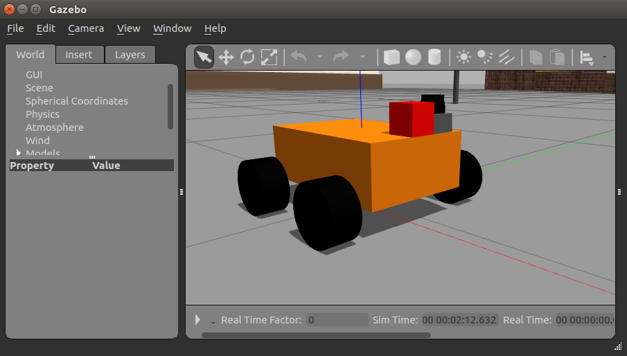
In the following screenshot, we can see the robot model with the simulated Hokuyo laser sensor as a small cylinder in black at the top and a red cube beside it that simulates the camera model:
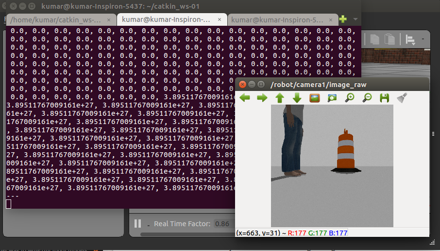
It is exciting to recognize that these simulated laser and camera sensors are generating real data, which can be viewed by using the rostopic echo command as follows:
$ rostopic echo /robot/laser/scan
$ rosrun image_view image_view image:=/robot/camera1/image_raw
The following screenshot shows the laser and camera output: