
Chapter 20
Moving Your Robot
By definition, all mobile robots move. To propel themselves across the floor, a robot might use wheels, or perhaps tracks, maybe even legs. Moving your robot is called locomotion, and how these wheels, tracks, and legs are arranged is called the drive geometry. There are many variations of drive geometries, some relatively easy to achieve, and others not.
Selecting the right locomotion system and drive geometry involves figuring out what you want your robot to do. But it also takes assessing the mechanical requirements of constructing the drive mechanism. It’s easy to “bite off more than you can chew,” and design a robot propulsion system that is not practical for you to build. A good example is robots with legs. These are much harder to build than wheeled bots, and they often require regular maintenance to keep everything tight and aligned.
In this chapter you’ll learn about locomotion systems and drive geometries, and how to select the best one for the robot you’re building.

Chapters 26 and 27 in Part 4 contain additional specific details about using locomotion principles to power three common types of robots: wheeled, tracked, and legged. This chapter introduces you to the basic concepts, plus issues common to all three varieties of locomotion systems.
Choosing a Locomotion System
Let us take a quick look at the three main locomotion systems used with mobile robots. Don’t worry if some of the terminology in the comparison table is new to you; I’ll explain it to you as we go along.
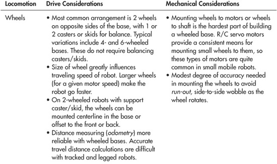
Locomotion Using Wheels
The drive geometry for robots that use wheels is defined by how each one is steered. There are a lot of choices.
DIFFERENTIAL STEERING
The most common way to move a robot is with differential steering. The most basic form consists of two wheels mounted on either side of the robot, as shown in Figure 20-1. It’s called differential steering because the robot is steered by changing the speed and direction (“difference”) between these two wheels.
A feature of most differentially steered robots is that they use one or two casters or skids, placed centerline over the robot in the front and/or back, to provide support for the base. See Chapter 26, “Build Robots with Wheels and Tracks,” for more information on selecting and using casters and skids with your robot designs.
Variations of the two-wheeled base include four or six wheels (4WD, 6WD), but the idea is the same. On bases that use more than two wheels, support casters or skids aren’t generally needed.
![]() One technique is the “dually” drive, where a single motor drives the two wheels on each side (see Figure 20-2). The wheels are linked together by a chain, belt, or gear system. The wheels on each side are located close together. This aids in steering, where the robot will pivot at a virtual point midway between the two wheels on each side.
One technique is the “dually” drive, where a single motor drives the two wheels on each side (see Figure 20-2). The wheels are linked together by a chain, belt, or gear system. The wheels on each side are located close together. This aids in steering, where the robot will pivot at a virtual point midway between the two wheels on each side.
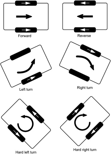
Figure 20-1 Differential steering involves using two motors on either side of the robot. The robot steers by changing the speed and direction of each motor.
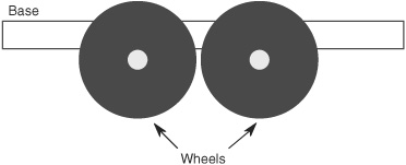
Figure 20-2 “Dually” wheels should be placed close to one another for maximum steering. If they are placed far apart, the robot cannot steer as easily.
![]() Another technique in 4WD systems, easier to implement but more expensive, is to power each wheel with a separate motor. The motors on each side are powered as if they were one unit: both motors on the left turn on or off at the same time.
Another technique in 4WD systems, easier to implement but more expensive, is to power each wheel with a separate motor. The motors on each side are powered as if they were one unit: both motors on the left turn on or off at the same time.
![]() And yet another technique for 4WD robots is to power only one motor per side and let the other one simply rotate freely.
And yet another technique for 4WD robots is to power only one motor per side and let the other one simply rotate freely.
Please don’t call this differential drive! Only robots that use a differential gearbox, like the one in an automobile, use “differential drive.” The correct term is differential steering—it’s how the robot steers that defines how it putt-putts down the hall. In fact, you might have noticed that all of the drive geometries discussed in this section actually describe the way the robot steers.
One of the key benefits of differential steering is that the robot can spin in place by reversing one wheel relative to the other, as shown in Figure 20-3.
CAR-TYPE STEERING
Pivoting the wheels in the front is yet another method of steering a robot. Robots with car-type steering (see Figure 20-4) are not as maneuverable as differentially steered bots, but they are better suited for outdoor use, especially over rough terrain.
Why even bother with car-type steering? It seems so twentieth century. Well, there are a number of valid reasons to use it. One of the greatest drawbacks of the differentially steered robot is that it will veer off course if one motor is even a wee bit slow. You can compensate for this by monitoring the speed of both motors and ensuring that they operate at the same RPM. This, of course, adds to the complexity of the robot.
Somewhat better traction and steering accuracy are obtained if the wheel on the inside of the turn pivots to a greater extent than the wheel on the outside. This technique is called Ackermann steering, and it is found on most cars but not as many robots.

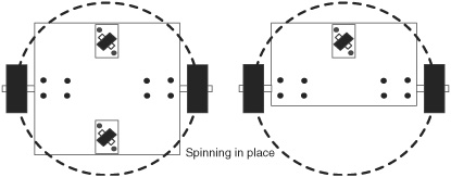
Figure 20-3 Differentially steered robots can turn in a circle within itself. This is called the steering circle, and the size of the circle depends on the dimensions of the robot and the placement of the wheels.

Figure 20-4 Car-type steering offers a workable solution for a robot used outdoors, but it’s less useful for a robot used indoors or in places where there are many obstacles to steer around.
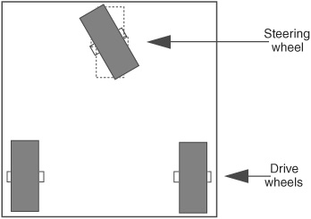
Figure 20-5 In tricycle steering, one drive motor powers the robot; a single wheel in front steers the robot. Beware of short wheelbases, as they can introduce tipping when the robot turns.
THREE-WHEELED TRICYCLE STEERING
Car-type steering makes for fairly cumbersome indoor mobile robots; a better approach is to use a single drive motor powering two rear wheels, and a single steering wheel in the front; the arrangement is just like a child’s tricycle (Figure 20-5).
The robot can be steered in a circle just slightly larger than the width of the machine. Be careful of the wheel base of the robot (distance from the back wheels to the front steering wheel). A short base results in instability in turns, causing the robot to tip over in the direction of the turn.
Tricycle-steered robots require a very accurate steering motor in the front. The motor must be able to position the front wheel with subdegree accuracy. Otherwise, there is no guarantee the robot will be able to travel a straight line. Most often, the steering wheel is controlled by a servo motor; servo motors used a “closed-loop feedback” system that provides a high degree of positional accuracy.
There are two basic variations of tricycle drives:
![]() Unpowered steered wheel. The steering wheel pivots but is not powered. Drive for the robot is provided by one or two other wheels.
Unpowered steered wheel. The steering wheel pivots but is not powered. Drive for the robot is provided by one or two other wheels.
![]() Powered steered wheel. The steering wheel is also powered. The two other wheels freely rotate.
Powered steered wheel. The steering wheel is also powered. The two other wheels freely rotate.
A subvariant of the tricycle base design reverses the functionality of the wheels: two wheels in the front of the robot steer, and a third wheel in the back provides support. The third wheel can even be a simple caster or omnidirectional ball (see the section on caster types, below).
OMNIDIRECTIONAL (HOLONOMIC) STEERING
All of the steering methods described so far are known as nonholonomic. This basically (and simplistically) means that in order for the robot to turn, it has to change the orientation of its body. A good example of nonholonomic steering is a car. It can turn, but only by following a circle described by the axis of its four wheels. The car cannot instantaneously move in any direction of the compass.
Holonomic drives are distinctive in that they allow motion in any direction, at any time. They can go straight ahead, then suddenly move 90° sideways—all without changing the orientation of the vehicle. A ball demonstrates holonomic movement: it can instantaneously travel straight, then move in any direction of the compass.
The common trait of holonomic steering systems is that the robot is omnidirectional, able to move in both the x and y directions with complete freedom. The most common form of holonomic robot base uses three motors and wheels, arranged in a triangle.
How Omnidirectional Steering Is Achieved
How exactly does this work? In the majority of robots that use holonomic steering, the secret is in the wheels. There are three wheels, each driven by a separate motor. Each wheel has rollers around its circumference—wheels within the wheels, as shown in Figure 20-6. The rollers are at some angle to the main wheel. The rollers provide traction to the wheel when the wheel is turning, but the rollers also let the wheel “slip” sideways to make turns.
The robot moves “forward” by activating any two motors; it turns by adjusting the speed or direction of any and all three of the motors (see Figure 20-7). These types of wheels were originally designed for materials handling, as a substitute for conveyor belts, but recently they’ve found new use in robot propulsion.
Other Forms of Omnidirectional Steering
Other forms of holonomic bases involve drive wheels that can each be independently rotated. These go by various names, such as synchronized omnidirectional. The rotation of each drive wheel can be accomplished by separate steering motors or by one steering motor that is linked—via a chain or cogged belt—to all of the drive wheels.
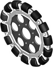
Figure 20-6 An example wheel used in a holonomic robot. Instead of a solid rubber tire, the rim of the wheel is composed of several rollers that are set at opposite angles to the rotation of the wheel.
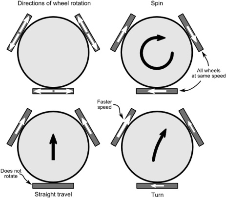
Figure 20-7 A holonomic vehicle steers by controlling the speed and direction of all of its wheels. For example, it goes forward by equally powering two wheels and letting the third “drag.” It spins by equally powering all three wheels. Turns are achieved by altering the speed and/or direction of each wheel.
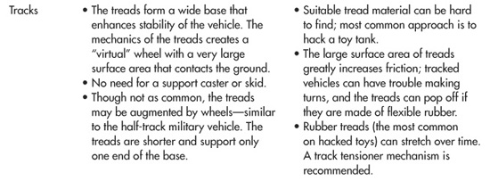
Locomotion Using Tracks
Since World War I the tank has become the symbol of military battles. The hulking mass of iron plowing over the earth, the shrieking sound of metal crushing against the ground, the blasts of fire from its cannon, all combine a sense of awe and respect. Little wonder that the tank design is popular among robot builders. The same principles that make a military tank superior for uneven terrain apply to robots or, in fact, any other type of treaded vehicle.
Too, a number of robots from science fiction films run on tracks. There’s Number Five from the movie Short Circuit, Robot B-9 from Lost in Space, and many others. Unlike their walking cousins, these robots actually look feasible. Their wide tracks provide a solid footing over the ground. Figure 20-8 shows plastic tracks on a small plastic robot.
Like the common two-wheeled bot, tracked robots are also differentially steered. Two long, chainlike tracks—also called treads—are mounted parallel to each side of the vehicle. A separate motor powers each track in either direction via a sprocket; the toothed design of the sprocket ensures that the drive mechanism doesn’t just spin if the track gets jammed. The tracks are kept inline by the use of idler rollers, placed at intervals along the sides of the vehicle.
Tracks turn by skidding or slipping, and they are best used on surfaces such as carpet or dirt that readily allow low-friction steering. Very soft rubber treads will not steer well on smooth, hard surfaces. To reduce friction, one approach is to always steer by reversing the tread directions.
Because of the long length of the track, tank bots don’t need a support caster or skid. The track acts as one giant wheel, one on each side.
![]() If both tracks move in the same direction, the robot is propelled in a straight line forward or backward.
If both tracks move in the same direction, the robot is propelled in a straight line forward or backward.
![]() If one track is reversed, the robot turns (Figure 20-9).
If one track is reversed, the robot turns (Figure 20-9).
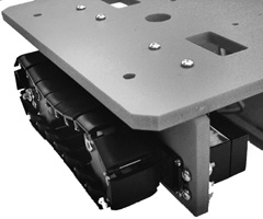
Figure 20-8 Individual links can be added or removed to lengthen or shorten these plastic tracks. Since the tracks don’t stretch, they won’t easily come off the drive sprocket of the robot. That can be a problem with rubber tracks.
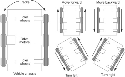
Figure 20-9 Differential steering using tracks is the same as with wheels, except that, to make a turn, one track needs to move in the opposite direction. If one track is stopped, the robot may “skitter” in the turn or the tracks may pop off.
This method is often referred to as tank steering or skid steering, but at the end of the day it’s the same as differential steering.
The main benefit of a tracked vehicle is its ability to navigate over rough terrain. The tracks enhance the “grip of the road,” allowing the robot to travel over loose dirt, sand, grass, and other surfaces that a wheeled robot can only dream about.
FYI
See Chapter 26, “Build Robots with Wheels and Tracks,” for additional information on track selection and use. You’ll also find several hands-on projects for building robots with tracks.
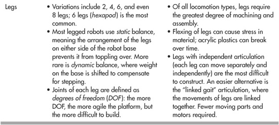
Locomotion Using Legs
Thanks to the ready availability of smart microcontrollers, along with the low cost of R/C (radio-controlled) servos, legged automatons like the one in Figure 20-10 are becoming a popular alternative for robot builders. Robots with legs require more precise construction than the average wheeled robot. They also tend to be more expensive.
Even a “basic” six-legged walking robot requires a minimum of 2 or 3 servos, with some six- and eight-leg designs requiring 12 or more motors. At about $12 per servo (more for powerful higher-quality ones), the cost can add up quickly!
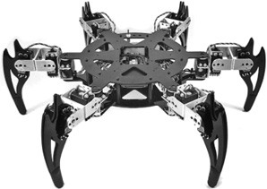
Figure 20-10 This six-legged hexapod robot uses 3 motors per leg, for a total of 18 motors. Because of the high number of motors, these kinds of robots are more difficult and more expensive to build. (Photo courtesy Lynxmotion.)
Obviously, the first design decision is the number of legs:
![]() Robots with one leg (“hoppers”) or two legs are the most difficult to build because of balance issues. In most two-legged bots the “feet” are oversized to offer the largest balancing area possible.
Robots with one leg (“hoppers”) or two legs are the most difficult to build because of balance issues. In most two-legged bots the “feet” are oversized to offer the largest balancing area possible.
![]() Robots with four and six legs are more common. Six legs offer a static balance that ensures that the robot won’t easily fall over. At any one time, a minimum of three legs touch the ground, forming a stable tripod.
Robots with four and six legs are more common. Six legs offer a static balance that ensures that the robot won’t easily fall over. At any one time, a minimum of three legs touch the ground, forming a stable tripod.
![]() Walking robots with eight (or more) legs are possible, but their construction cost and problems with higher weight make them largely impractical as a springboard for amateur robotics.
Walking robots with eight (or more) legs are possible, but their construction cost and problems with higher weight make them largely impractical as a springboard for amateur robotics.
FYI
Check out Chapter 27, “Build Robots with Legs,” for more information on constructing multilegged robots.
Locomotion Using Other Methods
While robots with wheels, tracks, and legs are the most popular among robot builders, that doesn’t mean there aren’t other ways of moving a robot. Here are just a few alternatives that you might develop as you build up your robot construction skills:
![]() Whegs combine the action of wheels and legs into one unit. They’re a favorite at the Biologically Inspired Robotics Laboratory at Case Western Reserve University, where they’ve adapted the idea from several robots designed for space and military use. An attribute of most (but not all) whegs is that they are compliant, meaning there is built-in flexibility to conform to the terrain.
Whegs combine the action of wheels and legs into one unit. They’re a favorite at the Biologically Inspired Robotics Laboratory at Case Western Reserve University, where they’ve adapted the idea from several robots designed for space and military use. An attribute of most (but not all) whegs is that they are compliant, meaning there is built-in flexibility to conform to the terrain.
![]() Flippers are similar to whegs but are intended primarily for locomotion across very sandy terrain or water. Whegs and flippers share common traits, allowing for amphibious robots that can go from land to water.
Flippers are similar to whegs but are intended primarily for locomotion across very sandy terrain or water. Whegs and flippers share common traits, allowing for amphibious robots that can go from land to water.
![]() Multisegment robots mimic the locomotion of caterpillars, snakes, and other crawling creatures. The robot crawls by systematically moving each segment a little bit at a time. Figure 20-11 shows an example hobby robot that is equipped with five segments. On the bottom of the segments are “peds” that provide traction across the floor.
Multisegment robots mimic the locomotion of caterpillars, snakes, and other crawling creatures. The robot crawls by systematically moving each segment a little bit at a time. Figure 20-11 shows an example hobby robot that is equipped with five segments. On the bottom of the segments are “peds” that provide traction across the floor.
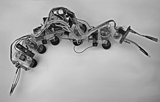
Figure 20-11 This segmented robot somewhat replicates the motion of a caterpillar. It uses radio control servo motors to move its segments side to side and up and down. Rubber pads on the bottom of the segments give it traction.
![]() Hydra robots combine two or more locomotion styles into one. For example, the robot may use articulated legs with wheels or small tracks as feet. Other types of hydra robots may combine the functionality of two front legs to serve as a gripper. The name hydra comes from Greek mythology; the Hydra was a beast with seven heads, who guarded the entrance to the underworld.
Hydra robots combine two or more locomotion styles into one. For example, the robot may use articulated legs with wheels or small tracks as feet. Other types of hydra robots may combine the functionality of two front legs to serve as a gripper. The name hydra comes from Greek mythology; the Hydra was a beast with seven heads, who guarded the entrance to the underworld.
![]() Unpiloted underwater robots use various propulsion means, such as propellers and thrusters, to move around in fresh and saltwater.
Unpiloted underwater robots use various propulsion means, such as propellers and thrusters, to move around in fresh and saltwater.
![]() Similarly, unpiloted flying bots are scale versions of planes and helicopters.
Similarly, unpiloted flying bots are scale versions of planes and helicopters.
On the Web: Managing the Weight of Your Robot
There’s more than will fit here. Check out the RBB Online Support site (see Appendix A) for free articles on how to manage the weight of your robot and best distribute that weight to avoid tip-overs and other embarrassing design problems.