
Chapter 25
Robot Movement with Shape Memory Alloy
Ametal with a memory? You bet. As early as 1938, scientists observed that certain metal alloys, once bent into odd shapes, returned to their original form when heated. This property was considered little more than a laboratory curiosity, but research into metals with memory took off in 1961, when William Beuhler and his team of researchers at the U.S. Naval Ordnance Laboratory developed a titanium-nickel alloy that repeatedly displayed the memory effect. Beuhler and his cohorts developed the first commercially viable shape memory alloy, or SMA. They called the stuff Nitinol, a fancy-sounding name derived from Nickel Titanium Naval Ordnance Laboratory.
Shape Memory Alloy Comes to Robotics
In 1985, a Japanese company, Toki Corp., unveiled a type of shape memory alloy specially designed to be activated by electrical current and made this material available in small quantities to business and hobbyists. The availability of short and inexpensive lengths of shape memory alloy for experimental use greatly enhanced the spread of interest in the material.
Toki’s shape memory alloy, trade-named BioMetal, offered all of the versatility of the original Nitinol, with the added benefit of near instant electrical actuation.
BioMetal and materials similar to it—Muscle Wire from Mondo-Tronics or Flexinol from Dynalloy—have many uses in robotics, including novel locomotive actuation. From here on out we’ll refer to this family of materials generically as shape memory alloy, or simply SMA.
Basics of Shape Memory Alloy
SMA is basically a strand of metal wire made with nickel and titanium. You know that titanium is a kind of “super-space-age” metal, about as strong as steel, yet some 50 percent lighter in weight. Though the material may be very thin (a typical thickness is 0.006″ (six mil)—slightly wider than a strand of human hair), it’s exceptionally strong.
In fact, the tensile strength of SMA rivals that of stainless steel: the breaking point of just one slender wire is a whopping 6 pounds. Even under this much weight, SMA stretches little. In addition to its strength, SMA also shares the corrosion resistance of stainless steel.
Shape memory alloys change their internal crystal structure when exposed to certain higher-than-normal temperatures, and this includes the induced temperatures caused by passing an electrical current through the wire. The structure changes again when the alloy is allowed to cool.
More specifically, during manufacture the SMA wire is heated to a very high temperature, which embosses or “memorizes” a certain crystal structure. The wire is then cooled and stretched to its practical limits. When the wire is reheated, it contracts because it is returning to the memorized state. That’s why SMA is often referred to as “memory wire.”
Shape memory alloys have an electrical resistance of about 1 ohm per inch. That’s far more than ordinary hookup wire, so SMAs will heat up more rapidly when an electrical current is passed through them. The more current that passes through, the hotter the wire becomes and the more contracted the strand.
Under normal conditions, a 2″ to 3″ length of SMA is actuated with a current of about 450 milliamps. That creates an internally generated temperature of about 100 to 130°C; 90°C is required to achieve the shape memory change. Most SMAs can be manufactured to change shape at most any temperature, but 90°C (194°F) is a standard value for off-the-shelf material.
Excessive current should be avoided. Why? Extra current causes the wire to overheat, which can greatly degrade its shape memory characteristics. For best results, current should be as low as necessary to achieve the contraction desired. SMAs will contract by 2 to 4 percent of their length, depending on the amount of current applied. The maximum contraction of typical SMA material is 8 percent, but that requires heavy current that can, over a period of just a few seconds, damage the wire.
Using Shape Memory Alloy
Shape memory alloys need little support paraphernalia. Besides the wire itself, you need some type of terminating system (the hardest part!), a bias force, and an actuating circuit. We’ll discuss each of these in the following sections.
TERMINATING SYSTEM
Because SMA can’t be readily soldered to anything, the ends have to be mechanically terminated—not the “Are you Sarah Conner?” type of terminating, but the kind involving crimp-on lugs and other kinds of solderless connectors. Because SMAs physically contract, using glue or another adhesive will not secure the wire to the mechanism. These and other crimp terminators are available from companies that sell shape memory alloy wire.
You can make your own crimp-on connectors using 18-gauge or smaller solderless crimp connectors—the smaller, the better. Although these connectors are rather large for the typical thin 0.006″ SMA, you can achieve a fairly secure termination by folding the wire in the connector and pressing firmly with a suitable crimp tool, as shown in Figure 25-1. Be sure to completely flatten the connector. If necessary, place the connector in a vise to squish it all the way shut.
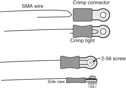
Figure 25-1 Use small crimp-on connectors to terminate the ends of the shape memory alloy wire. Small tools like those for making jewelry are a help.
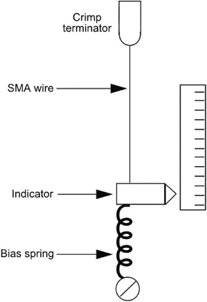
Figure 25-2 A bias spring or weight is required as a counterbalance on the SMA wire.
Figure 25-1 also shows a variation using miniature 2-56 size machine screws (available at hobby stores). You still use the crimp-on connector, but you carefully loop the wire around the machine screw.

Experience in making personal jewelry comes in handy when working with shape memory alloy. Many of the tools, techniques, and findings used to make things like necklaces and earrings can be used with SMA, too. Findings are the little doodads used along with the jewel in jewelry—metal chain, clasps, pins, and, of course, crimp-on connectors. Locate these tools and parts in well-stocked hobby stores and online at places such as Fire Mountain Gems.
BIAS FORCE
Apply current to the ends of an SMA wire, and it just contracts in air. To be useful,
![]() The wire must be attached to one end of the moving mechanism.
The wire must be attached to one end of the moving mechanism.
![]() It must be biased at the other end, like that in Figure 25-2. The bias can be a spring or even an unmovable part.
It must be biased at the other end, like that in Figure 25-2. The bias can be a spring or even an unmovable part.
Besides providing physical support, the bias offers the counteracting force that returns the SMA wire to its limber condition once current is removed from the strand. You can also use a second SMA wire that contracts in the other direction and restores the state of the first wire, but this involves some very detailed mechanical construction.
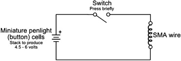
Figure 25-3 A simple switch in series with a battery forms a basic SMA driving circuit. The low current provided by the penlight cells delivers reduced current to the SMA wire, but don’t leave the switch closed for more than a second.
ACTUATING CIRCUIT
Basic SMA wire can be actuated with three or four 1.5-volt button cell (SR44) batteries (the cheap ones). Because the circuit through the SMA wire is almost a dead short, the batteries deliver close to their maximum current capacity. The average 1.5-volt button cell (SR44) battery has a maximum current output of only a few hundred milliamps, so the current is limited through the wire. You can connect a simple on/off switch in line with the battery, as detailed in Figure 25-3, to contract or relax the SMA wire. Press the button only briefly … just long enough for the wire to instantaneously contract.
![]()
The problem with this setup is that it wastes battery power, and if the power switch is left on for too long it can damage the SMA strand. A more sophisticated approach uses an LM555 timer IC that automatically shuts off the current after a short time. To save space, this bonus project is found on the RBB Online Support site. See Appendix A for details.
Operating SMA Using a Microcontroller
A microcontroller is the perfect tool for controlling shape memory alloy. With a simple program you can accurately control the amount of time an SMA wire is actuated. In contrast to using something like the LM555 timer, where you need to change component values to alter the amount of time the SMA is charged, all you need to do with a microcontroller is change a line or two of code.
A microcontroller also allows you to fully automate a sequence of SMA actuations, which you could use to create such things as a miniature caterpillar or some other clever arrangement of SMA wire.
You cannot connect the SMA wire directly to the microcontroller, however. You need to boost the current fed to the wire using a transistor or other driver. Figure 25-4 shows how to use a TIP120 Darlington power transistor, as well as a driver from an inexpensive and easy-to-use ULN2003 IC. This chip is composed of seven (count ’em, seven!) Darlington transistors, each capable of handling about half an amp.
With either approach, you can provide a higher voltage to the wire than the 5 volts shown; the increased voltage provides stronger and faster pulls. Experiment with different voltages (up a practical maximum of 9 to 12 volts), being careful to prevent excessive current through the wire. The higher the voltage, the easier it is to burn out your SMA strand. With higher voltages you might consider adding a 10 to 15 Ω (2-watt or higher) resistor between the V+ power supply and the SMA wire connection.
The sketch sma.pde is an example Arduino program that pulses the SMA wire (via a resistor and transistor, a ULN2003 IC interface) at 5-second intervals. Each pulse is limited to 250 milliseconds (a quarter of a second). You can also use the PWM feature of the Arduino to vary the duty cycle (on-versus-off) of the short pulse applied to the wire. Experiment with the time delays and PWM duty cycles. The example program uses a 3/4-second ON time.
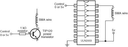
Figure 25-4 Two ways to activate SMA wire via a microcontroller: using a power transistor (in this case, a TIP120 Darlington) and the trusty ULN2003 integrated circuit. Shown here is an SMA wire connected to one of the seven drivers of the ULN2003.

sma.pde
You can also find this code at the RBB Online Support site. See Appendix A, “RBB Online Support.”

![]()
Be sure to power the driver circuit for the SMA wire from its own battery or power supply. Do not use the 5V pin on the Arduino to drive the wire, as the instantaneous current draw from the wire could overwhelm the Arduino’s voltage regulator. As usual, be certain to connect the grounds of the Arduino and your separate battery/power supply.
Experimenting with SMA Mechanisms
With the SMA properly terminated and actuated, it’s up to you and your own imagination to think of ways to use it in your robots. Figure 25-5 shows a typical application using an SMA wire in a pulley configuration. Apply current to the wire and the pulley turns, giving you rotational motion. A large-diameter pulley will turn very little when the SMA tenses up, but a small-diameter one will turn an appreciable distance.
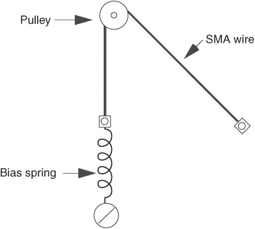
Figure 25-5 Concept of using an SMA wire with a mechanical pulley.
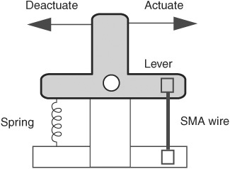
Figure 25-6 The bell crank changes the contraction of the SMA wire for sideways movement. The spring allows the crank to return to its original position after current is removed from the SMA wire.
Then in Figure 25-6 there’s a length of SMA wire used in a lever arrangement. Here, the metal strand is attached to one end of a bell crank. On the opposite end is an ordinary expansion spring, something you can get at most any hardware store. Applying juice to the wire causes the bell crank to move. The spot where you attach the drive arm dictates the amount of movement you will obtain when the SMA contracts.
SMA wire is tiny stuff, and you will find that the miniature hardware designed for model R/C airplanes is most useful for constructing mechanisms. Most any well-stocked hobby store will provide a full variety of bell cranks, levers, pulleys, wheels, gears, springs, and other odds and ends to make your work with SMA more enjoyable.
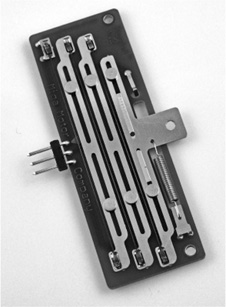
Figure 25-7 Commercially made SMA linear motor. (Photo courtesy Miga Motor Company.)
Using Ready-Made SMA Mechanisms
Several companies have taken up the shape memory alloy mantra and offer unusual and handy ready-made SMA mechanisms. Price is reasonable, especially considering that the products are ready for instant use; you don’t need to crimp on any connectors or attach any bias springs. One such company is Miga Motors (www.migamotors.com), which sells their wares through their own site plus a network of worldwide distributors, such as RobotShop and SparkFun.
Figure 25-7 shows the Miga Motors Dash, an SMA linear actuation that provides an astonishing 1.75 pounds of output force and a 1/4″ stroke. It’s intended for such applications as electronic door locks, but it has obvious uses in robotics as well, such as moving legs in a walking bot. Likewise, rotary SMA actuators can be used in place of servo motors in many applications. They’re spring-loaded, so once current is removed, the actuator returns to its starting position.