
Chapter 41
Remote Control Systems
The most basic robot designs—just a step up from motorized toys—use a wired control box for operation. You flip switches to move the robot around the room or activate the motors in the robotic arm and hand.
This chapter details several popular ways to achieve links between you and your robot. You can use the remote controller to activate all of the robot’s functions, or with a suitable onboard computer working as an electronic recorder, you can use the controller as a teaching pendant. You manually program the robot through a series of steps and routines, then play it back under the direction of the computer. Some remote control systems even let you connect your personal computer to your robot. You type on the keyboard, or use a joystick for control, and the invisible link does the rest.
![]()
Source code for all software examples may be found at the RBB Online Support site. See Appendix A, “RBB Online Support,” for more details. To save page space, the lengthier programs are not printed here, but you can find them on the support site. The support site also offers parts lists (with sources) for projects, updates, and more examples you can try!
Build a Joystick “Teaching Pendant”
No doubt you’ve been to Disneyland or other theme parks that use robotic or “animatronic” performers. These on-stage automatons are operated via a sophisticated computerized system that plays back the audio portion of the program and controls every movement of every robot on the stage.
Animatronic shows are most commonly “acted out” by a human director who operates a joystick or other control in real time. As the sound portion of the program is played, the director moves the joystick to operate the various animatronic devices onstage. The movements of the joystick are recorded for later playback. This same concept is used in many kinds of manufacturing robots, whose actions are programmed not from the keyboard but from a teaching pendant, a controller that records the actions of a human operator.
Using an older (but still available) game joystick for the IBM PC, you can create your own inexpensive teaching pendant for your robot (or animatron, if that’s to your liking). For this next project, I’ll use a common, garden-variety IBM PC-style analog joystick, one with a DB-15 (15-pin) gameport connector on it. While this style of joystick is no longer widely manufactured, it’s available cheap in surplus stores and resale shops. You may even have one lying about the house.

As an alternative to an old-fashioned analog PC joystick you may be able to hack a USB joystick to provide the same basic functionality of the old-style joystick. What you’re after is the analog voltage from the wiper of the joystick, and the push-button contacts of two buttons. If you’ve got a USB joystick you’re no longer using, open it up and see how easy it would be to hack.
Figure 41-1 shows the pinout of the DB-15 (15-pin) gameport connector. The pin functions are summarized in the following table. Note that the connector supports up to two separate joysticks, joined with a Y cable. In this project you only use one joystick (Joystick 1) and its two buttons (Button 1 and Button 2).
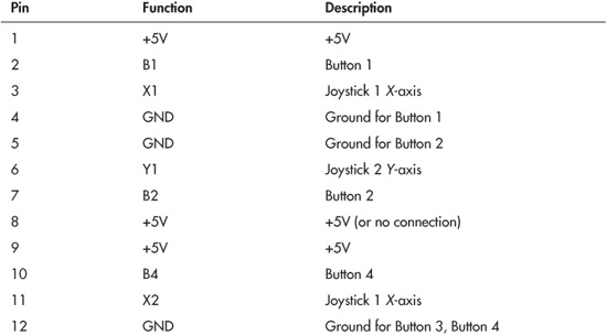
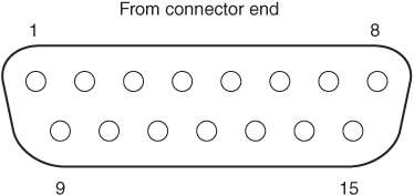
Figure 41-1 The 15-pin gameport connector used on older-style PC joysticks. This is the connector as viewed straight on.

Programming allows the joystick teaching pendant to control the motors of a two-wheel robot. You can record and play back up to 30 seconds of commands. You can also use the joystick teaching pendant in “free” (no record or playback) mode, where you control the robot by manually pushing the stick.
For the control electronics, we’ll connect the joystick to an Arduino microcontroller by way of a simple interface. Figure 41-2 shows how the joystick connects to the Arduino board. The Arduino, in turn, connects to whatever motor control electronics you are using.
IBM PC–style joysticks contain analog potentiometers; the resistive value of these pots changes as you move the joystick around. We actually won’t be using the analog nature of the joystick for this project, but you can add this feature on your own if you wish. For example, instead of controlling the power and direction of the motors, you could rig the joystick so that the more you push on the stick, the faster the motor goes.

Arduino Joystick—joystick.pde
To save space, the program code for this project is found on the RBB Online Support site. See Appendix A, “RBB Online Support,” for more details.
USING THE JOYSTICK TEACHING PENDANT
Test the program by pushing the joystick. For the purposes of verification and testing, the joystick.pde program uses the Arduino Serial Monitor window (choose Tools, Serial Monitor) to display the binary value of the 4 motor control bits (only the last 4 bits are used). For example, when you push the joystick the value 00000101 is shown in the Serial Monitor window. The last four bits are 0101:
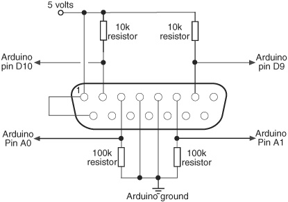
Figure 41-2 Only simple interface electronics are needed between a joystick with a 15-pin gameport plug and an Arduino microcontroller.
A value of 0 for LeftMotDir/RightMotDir means the motor is going forward (conversely, a value of 1 means the motor is going in reverse). A value of LeftMotCtrl/RightMotCtrl means that the motor is activated. With the bits 0101, both motors are operating and are going forward. Note that the program samples the position of the joystick once every half-second.
RECORDING AND PLAYING BACK STEPS
Briefly depress button 1 (usually labeled as the “fire” button). A “Recording On” message is displayed in the Serial Monitor window. The joystick is now in record mode, and the joystick positions are being stored in memory. Recording is simple in the joystick.pde program: each half-second, the joystick position is stored in one element of a 60-element array. Since there are 60 elements and a new “snapshot” of the joystick controls is made every half-second, this means there is a maximum of 30 seconds of recording.
You can revise the program to add longer programming time, but note that, like all microcontrollers, the Ardunio has only so much memory for data storage. The more elements there are, the more memory is consumed.
When you are done recording the steps you want, briefly depress button 1 again. The joystick will be taken out of record mode. You can play back your previously stored steps by briefly depressing button 2. While a previously stored set of steps is being played, any joystick motions are ignored. If necessary, you can abort play mode at any time by depressing button 2 again. When playback is complete, the program automatically goes back into “free-run” mode.
Commanding a Robot with Infrared Remote Control
You can use a TV remote control to operate a mobile robot. A computer or microcontroller is used to decipher the signal patterns received from the remote via an infrared receiver. Because infrared receiver units are common finds in electronics and surplus stores, adapting a remote control for robotics use is actually fairly straightforward.
It’s mostly a matter of connecting the pieces together. With your infrared remote control you’ll be able to command your robot in just about any way you wish—to start, stop, turn, whatever.
SYSTEM OVERVIEW
Here are the major components of the robot infrared remote control system:
![]() Infrared remote. Most any modern universal infrared remote control, like the one in Figure 41-3, will work. These are priced starting at a few bucks at most any discount store, and I’ve even seen them at dollar stores. Important: You want a universal remote that supports Sony TVs and other Sony brand gear—98 percent of all universal remotes do, but check just to be sure.
Infrared remote. Most any modern universal infrared remote control, like the one in Figure 41-3, will work. These are priced starting at a few bucks at most any discount store, and I’ve even seen them at dollar stores. Important: You want a universal remote that supports Sony TVs and other Sony brand gear—98 percent of all universal remotes do, but check just to be sure.
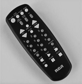
Figure 41-3 Example universal infrared remote control. To use a universal remote with the PICAXE microcontroller, you must select the code for a Sony TV, VCR, or other home electronics device.
![]() Infrared receiver/demodulator. This all-in-one module contains an infrared light detector, along with various electronics to clean up, amplify, and demodulate the signal from the remote control. The remote sends a pattern of on/off flashes of light. These flashes are modulated at about 38 to 40 kHz in order to reduce interference from other light sources. The receiver strips out the modulation and provides just the on/off flashing patterns.
Infrared receiver/demodulator. This all-in-one module contains an infrared light detector, along with various electronics to clean up, amplify, and demodulate the signal from the remote control. The remote sends a pattern of on/off flashes of light. These flashes are modulated at about 38 to 40 kHz in order to reduce interference from other light sources. The receiver strips out the modulation and provides just the on/off flashing patterns.
![]() Computer or microcontroller. You need some hardware to decode the light patterns, and a computer or microcontroller, running appropriate software, makes the job straightforward. For this project we’ll use the PICAXE microcontroller, because it has a very handy built-in command for directly reading the codes sent by Sony remote controls. The same techniques described here can be used with other microcontrollers, but you’ll need to adapt the program.
Computer or microcontroller. You need some hardware to decode the light patterns, and a computer or microcontroller, running appropriate software, makes the job straightforward. For this project we’ll use the PICAXE microcontroller, because it has a very handy built-in command for directly reading the codes sent by Sony remote controls. The same techniques described here can be used with other microcontrollers, but you’ll need to adapt the program.
INTERFACING THE RECEIVER/DEMODULATOR
The first order of business is to interface the receiver/demodulator to the PICAXE. Most any receiver module for 38-kHz infrared operation should work well. I’ve specified the Vishay TSOP4838 because (at least as of this writing) it’s widely available and fairly inexpensive. But you can use just about any other infrared receiver/demodulator that operates at 38 kHz. For experimenting, you can use a solderless breadboard to make the connections.
In developing this project I came across some very old infrared receiver-demodulators in my parts bin that only supported 5-volt operation—the modern ones work over a wider voltage range. If you happen to have one of these ancient modules, you can still use it in your project, but be sure to operate your circuit at 5 volts. It won’t function, or will behave erratically, at anything under about 4.6 volts.
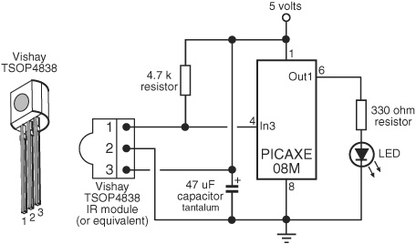
Figure 41-4 Connection diagram between infrared receiver/demodulator and the PICAXE 08M microcontroller. An LED provides visual feedback.
Figure 41-4 shows the simple interface for the infrared receiver-demodulator to a PICAXE 08M microcontroller. You can use any larger PICAXE microcontroller, as long as it supports the infrain2 command. If you do use another version of the PICAXE chip, remember to change the pins for power, ground, and input, accordingly. Figure 41-4 also shows the pin assignment of the TSOP4838 receiver/demodulator.
The PICAXE supports a number of built-in commands for decoding signals from an infrared remote control. There’s also the infrain and irin commands, supported by various versions of the PICAXE chip. Refer to the PICAXE documentation for the details on these commands.
PROGRAMMING THE PICAXE
Sonyremote.bas is a simple demonstration program for use with the PICAXE, which appears below. Refer to Chapter 38, “Using the PICAXE,” for more information on how to use the chip, including how to compile, download, and execute programs. For now, I’ll assume you’re familiar with all these things and cut right to the chase.
To use the program, be sure to set your universal remote control to output Sony TV infrared codes. The remote control will come with an instruction booklet on how to select the proper code setting. Look under the TV listing for Sony and note which code number(s) to use. You may need to try several of them before you will have positive results.
For these projects I used an RCA-brand model RCU403 universal remote control. These, and their close cousins (like the RCU410, available at RadioShack), are common finds at department stores and online outlets, and they are priced at under $10 (sometimes a lot less). The exact model you use isn’t critical, as long as it supports Sony TVs and VCRs.
I used code 002 for TV, and 099 for VCR/DVD—the VCR/DVD codes provide support for the Play/Rew/FF/etc. shuttle controls at the bottom of the remote. There are other Sony codes supported as well, and using them may result in different behaviors. Experiment.
sonyremote.bas

DETERMINING CONTROL VALUES
In sonyremote.bas the values 1 and 4 represent the 2 and 5 buttons. But how did I know that? I used a simple debug program that displayed the values in the PICAXE Debug window:
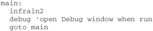
Like all programs that use the Debug window, your PICAXE must be connected to your computer via its serial or USB download cable, so that the controller can send back values. The b13 variable represents the data collected by the infrain2 command. As you press buttons on the remote, the first column for b13 in the Debug window shows the numeric equivalent of the infrain2 value. For example, pressing the On/Off button displays a 21.
Different PICAXE chips support other versions of infrared decoding commands. For example, the PICAXE 18X and 28X chips support infrain, which works in a similar manner to infrain2, except that it automatically “adjusts” the value of codes returned by the numeric keypad and other keypresses—that is, pressing the “1” key returns a 1. The infrain command is now considered obsolete, so use either infrain2 or, on PICAXE parts that support it, irin.
I got the following results for the RCA403, set to VCR/DVD with code 099, testing both infrain2 and infrain:


Note: infrain2 and irin share the same code values.
CONTROLLING ROBOT MOTORS
Let’s assume you want to drive the traditional two-motor robot, using DC motors. You could use the PICAXE 08M, which has just enough I/O pins for the job. But that doesn’t leave any pins for other tasks. Unless you plan on using the 08M just as an infrared signal decoder, you’ll want to select a PICAXE chip with more pins.
Figure 41-5 shows a wiring diagram for using the PICAXE 18M2 to steer a robot based on buttons pressed on a universal remote. The 18M2 has more than enough I/O pins for what we want to do, allowing you room for other hardware expansion. The code is ir-bot.bas.
By itself, the PICAXE lacks the drive current to power the motors, so a motor driver circuit is used between the chip and the two motors. See Chapter 22, “Using DC Motors,” for more information on motor driver circuits. Figure 41-5 shows connecting to the popular L293D motor H-bridge IC, which handles smallish motors up to 600 mA current draw. Note that the circuit specifically uses a separate 6-volt power supply for the motors. This makes things a lot easier all the way around, and the regulated 5-volt supply for the PICAXE can remain small and simple.
Note: Whatever motor drivers you use, make sure that you include 0.1 μF polyester or ceramic disc capacitors directly across the terminals of the motor. These decoupling capacitors prevent excess electrical noise from appearing on the signal line from the IR receiver-demodulator. As noted in Chapter 21, “Choosing the Right Motor,” DC motors—particularly the inexpensive kind—generate copious noise from radio frequency (RF) interference as well as “hash” in the power supply lines of the circuit.
The circuit also shows larger-value capacitors used to condition the power line. These also prevent electrical motor noise from disrupting the received infrared signals. If you notice that you can turn the motors on, but not off, noise is probably the culprit.

Figure 41-5 Using a PICAXE 18M2 microcontroller to receive signals from a compatible infrared receiver/demodulator and an H-bridge motor driver. Refer to Chapter 22 for details on using motor drivers.
ir-bot.bas
To save space, the program code for this project is found on the RBB Online Support site. See Appendix A for more details.
OPERATING THE ROBOT WITH THE REMOTE
Now that you have the remote control system working and you’re done testing, it’s time to play! With ir-bot.bas downloaded, disconnect the PICAXE from its programming cable, set your robot on the ground, and apply all power. In the beginning, the robot should not move. Point the remote control at the infrared receiver-demodulator, and press the following buttons to command the robot:
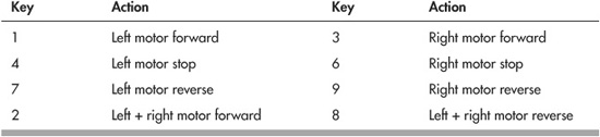
You may press 5 to stop both motors.
SPECIAL CONSIDERATIONS
Keep the following in mind when experimenting with this project:
![]() Your robot spins when it should go forward? Reverse the leads to one of the motors to change its polarity. For example, switch the wires to pins 11 and 14 on the L293D.
Your robot spins when it should go forward? Reverse the leads to one of the motors to change its polarity. For example, switch the wires to pins 11 and 14 on the L293D.
![]() The infrain2 command is sensitive to the operating speed of the PICAXE chip. As noted in the PICAXE documentation, use infrain2 at the default 4-MHz speed only.
The infrain2 command is sensitive to the operating speed of the PICAXE chip. As noted in the PICAXE documentation, use infrain2 at the default 4-MHz speed only.
![]() Press only one button on the remote at a time. If you want to create combinational events, use another button to code those events into your program. For instance, you might use Volume Up/Down or Channel Up/Down to move the robot straight forward and backward.
Press only one button on the remote at a time. If you want to create combinational events, use another button to code those events into your program. For instance, you might use Volume Up/Down or Channel Up/Down to move the robot straight forward and backward.
![]() Infrared links work best when used indoors, out of direct sunlight and away from bright light sources.
Infrared links work best when used indoors, out of direct sunlight and away from bright light sources.
![]() The better remote controls put out more light power, allowing you to operate your robot from greater distances. Depending on the model of your remote, you may be limited to about 6 to 8 feet away in controlling the bot.
The better remote controls put out more light power, allowing you to operate your robot from greater distances. Depending on the model of your remote, you may be limited to about 6 to 8 feet away in controlling the bot.
![]() If your robot doesn’t appear to react when you press buttons, or if it behaves erratically, double-check your wiring, or try another Sony product code for the remote. Or try a different remote.
If your robot doesn’t appear to react when you press buttons, or if it behaves erratically, double-check your wiring, or try another Sony product code for the remote. Or try a different remote.
On the Web: Control by Radio Signal
Remotely controlling a robot by way of wires or infrared limits the range to just a few feet. And when operated by wire, the robot’s tether might get caught up on things, snagging itself on its own lifeline.
You can extend the range of communication by switching to radio frequency (RF) remote control. Though more expensive to implement, remoting by RF is more flexible; the signals work around corners (infrared control works by line of sight) and, with the right radio units, can even broadcast video pictures back from the robot.
If you’re interested in commanding your robot via radio waves, see the RBB Online Support site (check Appendix A for details). There you’ll find information on:
![]() Types of communications: simplex, half-duplex, and full-duplex
Types of communications: simplex, half-duplex, and full-duplex
![]() 802.11 WiFi, Bluetooth, and Zigbee communications standards
802.11 WiFi, Bluetooth, and Zigbee communications standards
![]() Using a data radio with your robot
Using a data radio with your robot
![]() Maximizing radio signal range
Maximizing radio signal range
Broadcasting Video
Telerobotics is the technique of remotely controlling a robot vehicle while it’s simultaneously broadcasting video pictures to you. If you’ve gotten as far as operating your robot via any kind of remote control, adding video to the mix is fairly simple. There are two general approaches:
Feed the video signal back through the data radio. This works if you’re using 802.11g (or faster) WiFi, as you need the higher data rates to keep up with the video. This is a doable approach if the video is already in digital format; if you’re using an analog camera, you’ll need to digitize it before passing it back through the communications link.
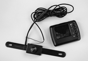
Figure 41-6 Backup camera system, designed to be mounted on the rear license plate holder of a car or van. The camera broadcasts color video to the receiver, which contains its own LCD screen.
You’d use this technique, for example, if your robot were equipped with a laptop or other computer with a USB port; you could capture video using a Web camera that, in turn, sent its signals via radio signal back to you.
Use a separate analog video transmitter. This approach works with any kind of remote control, because it doesn’t use the data link for the transmission of video. You use your regular wired, infrared, or radio link, but the video is sent back using its own transmitter.
Wireless cameras are pretty inexpensive, and many are already designed for use with low voltage supplies. Figure 41-6 shows a wireless “car backup camera” that is designed to mount to the license plate holder on the rear of an automobile. The receiver is mounted on the dash and, using a small LCD screen, displays the image broadcast by the camera. Naturally, both are designed to work with a standard 12-volt car system. I bought this particular unit at a closeout sale for about $20.
When looking for a wireless camera ensemble for the hole, find one powered with external wall transformers. These are the easiest to hack for mobile robotics use. On many low-cost wireless cameras, the receiver is intended to be plugged into a USB port, for viewing on a computer. This is handy if that’s how you want to teleoperate your robot.
If it’s not, you want a receiver that can plug into any standard video input, so you can view the picture. Some wireless cameras have audio, which is handy. Older wireless surveillance cameras broadcast only in black and white, and the picture is worse than terrible. Stay away from these. Modern wireless cameras provide a reasonably sharp color image with plenty of detail … useful when piloting your robot through a maze of living room furniture, curious family pets, and young children bent on destroying anything that moves.