
Chapter 19
Robot Power Systems
You learned about batteries in the preceding chapter. Now you can go about using them in your robot designs. That takes attaching the battery (or battery pack) to the robot and stringing wires from the battery to the motors and electronics of your robot.
Easily enough said, but the specifics are a bit more than this. This chapter cracks what you need to know to apply power systems to your robots.
FYI
This chapter makes reference to common electronic components, such as resistors, capacitors, and diodes. If you’re new to these subjects, be sure to check out Chapter 30, “Building Robot Electronics—the Basics,” and Chapter 31, “Common Electronic Components for Robotics.” You may also want to check out the newbie lessons in My First Robot, located on the RBB Online Support site. See Appendix A.
Power and Battery Circuit Symbols
Let’s start with the symbols used in electronic circuit designs to denote power and battery sources. Schematics are the road maps of electronic circuits. And in most circuits, it all starts with the power connection. For robotics, that power typically comes from batteries. Figure 19-1 shows the most commonly used symbols for power and batteries.
![]() When power comes from an arbitrary source (batteries, connection from wall transformer, whatever), it’s often shown as a small circle, or sometimes an upward-pointing arrow. To complement the power connection, the circuit will also show another connection for ground. The exact form of the ground symbol is varied, but the set of three lines tapering to a point is among the most common.
When power comes from an arbitrary source (batteries, connection from wall transformer, whatever), it’s often shown as a small circle, or sometimes an upward-pointing arrow. To complement the power connection, the circuit will also show another connection for ground. The exact form of the ground symbol is varied, but the set of three lines tapering to a point is among the most common.
![]() When power comes from a battery or battery pack, the symbol indicates the positive connection with a + (plus) sign. The − (negative) connection is inferred.
When power comes from a battery or battery pack, the symbol indicates the positive connection with a + (plus) sign. The − (negative) connection is inferred.
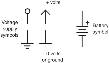
Figure 19-1 Various common battery symbols used in electronic diagrams. This book uses the ones on the left and right.

There are lots of different names for the ground connection. You may also encounter common, negative, 0 volts, 0V, return, chassis, and earth. These terms don’t always mean the same thing, depending on the application. But for general electronics and robotics work, unless otherwise noted in the description of the circuit you can assume the terms are interchangeable.
Using a Premade Battery Pack
Many of today’s consumer products use rechargeable battery packs. So can your robot. The battery pack can use cells that fit into all shapes and sizes of battery compartments. Wires and a quick-disconnect plug allow easy removal of the batteries, for things like recharging or replacement.
You can rob the battery pack out of a discarded consumer electronics device, such as a cordless phone you no longer need. You’ll then have batteries for your robot, as well as the charger that came with the phone.
Or you can purchase replacement packs, though these can carry a premium price. This approach is worthwhile only if you already have a recharger for the pack. Otherwise, you’re better off using battery packs designed for radio control (R/C) applications, as detailed next.
USING PREMADE R/C BATTERY PACKS
Radio control (R/C) applications, like model airplanes and model cars, are power hungry. High-capacity rechargeable battery packs are the norm. The packs are available in a variety of voltages and capacities from any local or online store specializing in R/C cars and planes. Common packs voltages are:
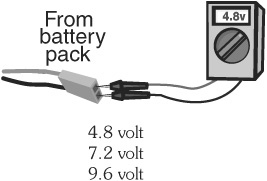
The 7.2-volt packs are perhaps the most useful for robotics. Note the fractional voltages in this list. These are the result of the 1.2-volts-per-cell batteries used inside the packs. Current capacities range from about 350 milliamp-hours (mAh) to over 1500 mAh. The higher the current capacity, the longer the battery can provide juice to your robot. Unfortunately, higher-capacity batteries also tend to be larger and heavier.
You should always pick the capacity based on the estimated needs of your robot, rather than just selecting the biggest brute of a battery that you can find. Bigger batteries weigh more and they cost more. As you work more with robotics you’ll get a sixth sense for the sizes of the batteries you need to power your creations.
PACKS WITH NICD OR NIMH BATTERIES
As you read in Chapter 18, “All About Batteries,” the two types of rechargeable batteries that are both easy to find and affordable are nickel-cadmium (NiCd) and nickel metal hydride (NiMH). Both are frequently used in R/C applications, and both can be recharged many times. Of the two, NiCd batteries are the least expensive because they’ve been around the longest. NiMH batteries provide for high capacities, with ratings of 900 to 3000 mAh, and over.
Both NiCd and NiMH battery packs require rechargers designed for them. The better battery rechargers work with a variety of pack voltages. I recommend these so you don’t have to keep multiple chargers around.
Making Your Own Rechargeable Battery Pack
The shape and layout of your robot may make it difficult for you to use a standard-size battery pack or one of the battery holders detailed in the next section. You can always make your own battery pack, using rechargeable cells designed to be soldered together. These are special battery cells with solder terminals on them. They also come in so-called fractional sizes—a 2/3 AA cell is the same diameter as a standard AA cell, but roughly (about, kinda sorta) 2/3 the length.
You can arrange the cells in whatever layout best suits the space constraints of your robot. Remember that when batteries are connected one after the other in a string (series), the volts of each cell are added together. When the batteries are connected side by side (parallel; see Figure 19-2), the current-carrying capacity of the cells are added together.
Most battery packs use cells in series. Start with one cell, and wire its positive terminal to another cell’s negative terminal, like that in Figure 19-3. Continue until all the cells are connected.
If you need to attach the cells using wire, match the gauge of the wire with the current demand from the battery. Thicker wire can handle more current. A good starting size is 14-or 16-gauge stranded (not solid) wire. See Appendix D, “Electronic Reference,” for a comparison of wire gauges. Just remember: the lower the number, the larger the wire.
After you’ve soldered the batteries together, use “battery shrink-wrap,” a PVC plastic tube to enclose everything into one nice package. Use a hair dryer on high to shrink up the plastic so it makes a snug fit around the batteries. But be sure the PVC doesn’t get so hot it burns. Battery shrink-wrap is available at many hobby stores catering to builders of R/C airplanes and cars, as well as online battery outlets.
To complement the pack, you’ll need a compatible battery charger that is designed not only for the total voltage of all the cells, but for the type of cells and their amp-hour capacity. Rechargers are available for either NiCd or NiMH (some are switchable), with common voltage ratings as follows:
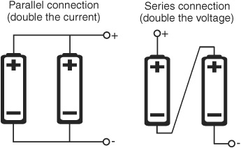
Figure 19-2 Batteries can be connected in series or in parallel. Parallel connection is seldom used, as current from the strongest battery is drained even when the pack is not connected to a circuit.
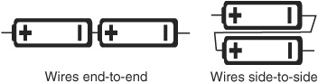
Figure 19-3 Batteries with solder tabs may be wired side to side or end to end, whatever makes the best shape for the intended use.

In-between voltages are also possible, using an odd number of cells. Seven cells of either NiCd or NiMH batteries is 8.4 volts, for example. You just need to make sure your battery charger is adjustable for that voltage. Some chargers will work with packs within a range—say, 9.6 to 18 volts. The recharger automatically adjusts to the proper voltage.
Use a polarized connector so you can easily hook up your battery to the rest of your robot. Never leave the wires bare, as this increases the chance of a short circuit. Shorting freshly charged batteries can cause fire or burns and can permanently damage the battery.
Using Battery Cells in a Battery Holder
Perhaps the most convenient method of using batteries with your robot is with a battery holder. Electrical contacts in the holder form the proper connections from the cell-to-cell; the voltage at the holder terminals is the sum of all the cells.
Holders are available for all the common battery sizes and even for some of the not-so-common ones. (However, if you plan on using the fractional AA size, or one of the subsizes, you are better off building a battery pack, as detailed previously.) Holders for two and four cells are among the most common. Battery holders come in either plastic or metal. The plastic holders are a tad more bulky, but they are lighter, cheaper, and easier to mount.
Battery holders often must conform to the shape of the object they are used in, so there are plenty of variations in how the cells are laid out—for example, a four-cell holder may orient the cells all in a single row, or it might pack them side by side. See Figure 19-4 for some examples of single-side battery holder layouts. There are even more variations for battery holders with cells on both sides.

Figure 19-4 Sampling of battery holder layouts. Only a single side of the holder is shown here; the same layouts are available in double-sided holders, which carry twice the number of cells.
MOUNTING BATTERY HOLDERS TO YOUR ROBOT
Single-and multicell battery holders can be readily secured to your robot using any of three basic methods:
![]() Fasteners provide a solid mounting. Most holders have mounting holes for use with small machine screw hardware. Use 2-56 hardware, or drill out the holes for larger screws. Opt for flat-headed screws, and insert the screws through the holder first—this way the screw hardware will not interfere with the batteries.
Fasteners provide a solid mounting. Most holders have mounting holes for use with small machine screw hardware. Use 2-56 hardware, or drill out the holes for larger screws. Opt for flat-headed screws, and insert the screws through the holder first—this way the screw hardware will not interfere with the batteries.
![]() Velcro, Dual Lock, or similar two-part hook-and-loop allows you to mount the holder to your robot but still pull it off when you need to. The two parts of the hook-and-loop can be readily separated. Simply remove the holder, exchange the batteries, then press the holder back into place.
Velcro, Dual Lock, or similar two-part hook-and-loop allows you to mount the holder to your robot but still pull it off when you need to. The two parts of the hook-and-loop can be readily separated. Simply remove the holder, exchange the batteries, then press the holder back into place.
![]() Double-sided adhesive or foam tape provides a quick and easy method of mounting a battery holder. Like hook-and-loop, the mounting is semipermanent; even the strongest foam tape can often be dislodged with some effort. However, reserve this method for when you don’t need to often remove the holder from its place in your robot.
Double-sided adhesive or foam tape provides a quick and easy method of mounting a battery holder. Like hook-and-loop, the mounting is semipermanent; even the strongest foam tape can often be dislodged with some effort. However, reserve this method for when you don’t need to often remove the holder from its place in your robot.
Try to mount the holder in a location that allows for ready access to the battery cells, so you can easily get to them. As necessary, consider the underbelly of the robot. Most holders secure the cells with a tight fit, so you can mount the holder upside down and the batteries should not (normally) fall out.
SNAPS AND CLIPS FOR 9-VOLT BATTERIES
Use a polarized battery snap for 9-volt batteries. Secure the battery to your robot with a 9-volt battery clip; these are available for either front or side mount. I like the metal holders, as you can manually squeeze the tangs together to make for a tighter fit against the battery.
Mount the clip to the robot using double-sided foam tape, hook-and-loop, or fasteners. I prefer the fastener approach when a permanent installation is required and I want to make sure the battery stays put.
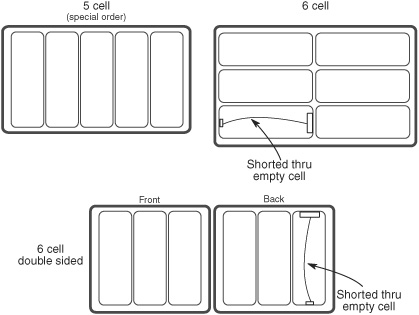
Figure 19-5 Create your own “odd-number cell” battery holders by bridging across the terminals of one of the cell pockets. This maintains electrical continuity for the holder but lets you use one fewer batteries.
BATTERY HOLDERS FOR “IN-BETWEEN” VOLTAGES
Sometimes you may want an in-between voltage. Just use an odd number of cells. For instance, five rechargeable cells provides 6 volts; five nonrechargeable cells, 7.5 volts. While they do make battery holders for odd numbers of cells, they’re not always easy to find, and they tend to be more expensive.
One alternative is to use a standard even-cell holder and “bridge” one of its cell “pockets” to produce an odd-cell voltage. A four-cell AA holder provides 6 volts—too much for electronics designed for 5 volts. By removing one cell from the holder, the voltage is reduced to 4.5 volts, which is within the normal operating range.
Figure 19-5 shows the concept of bridging a cell pocket in a six-cell holder, which is commonly available in both single-and double-sided versions. You can bridge the pocket temporarily by using a jumper clip. For a permanent job you’ll want to solder a length of wire between the battery posts in the last cell pocket.
![]()
There’s more about batteries, battery holders, and battery packs on the RBB Online Support site (see Appendix A for more details).
Best Battery Placement Practices
For obvious reasons, the battery in your car is intentionally mounted for easy access. The same obvious reasons apply to robots. When possible, the battery holder or pack for your bot should be located where it affords quick and reliable access.
One ideal location for the battery pack or holder is on the underside of the robot. This assumes there is enough ground clearance between the robot and the floor. Mounting on the bottom allows for quick access to the cells, either for replacement or recharging: just turn the robot over. And it saves space for electronics and other parts. Avoid any location that requires you to dismantle lots of parts of the robot just to access the batteries.
Wiring Batteries to Your Robot
There are lots and lots of ways to wire batteries to the rest of your robot. Picking the right method depends on the design and complexity of your bot.
In all cases, it’s important to use a wiring system that eliminates the chance of short-circuiting the terminals of the batteries. It’s also a good idea to use a connection scheme to prevent damage if the battery pack is connected to the robot circuitry in reverse, as detailed in the following section
Simple bots, replaceable cells. For the most basic robots, using battery holders with individual cells, you can merely solder the battery pack to the electronics and motors. To replace or recharge the batteries, just remove them from the holder.
Solderless breadboards. Rather than solder to the electronics, insert the wires from the pack into the + and − rails of the breadboard. You’ll need to solder a short (half-inch) length of 22-gauge solid conductor wire to the end of the battery pack leads, so you can plug into the breadboard.
Rechargeable packs with a standard 0.100″ two-prong female plug. Use corresponding male header pins on your circuit or breadboard so you can readily connect and disconnect the batteries. Danger! This poses a chance of reverse polarity, so consider one of the solutions under “Preventing Reverse Battery Polarity” (later in this chapter).
Battery packs with a polarized plug. Use the corresponding socket on your circuit board or breadboard. A popular polarized connector found on DC wall transformers (see Figure 19-6) is the coaxial barrel plug, discussed in the next section. It can also be used on battery holders; use a six-cell (7.2-or 9-volt) holder and a 2.1mm barrel plug to power an Arduino board with batteries.
Battery packs with a customized polarized plug. You can make your own polarized connector systems or adapt one from the battery packs used in R/C model airplanes and cars. These are also discussed in the next section.
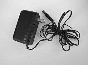
Figure 19-6 Wall transformer with a barrel plug. If purchasing a wall transformer for your robotics projects, make sure it provides the correct voltage and that the plug has the proper polarity to match your components.
Preventing Reverse Battery Polarity
At all costs, avoid reversing the connection of your batteries when you plug them into your robot. At best, your bot won’t function; at worst (more likely), you’ll instantaneously blow out some or all of the electronics. There are two general choices: mechanical interlock and electronic polarity protection.
MECHANICAL POLARIZED CONNECTIONS
You can reduce and even eliminate the possibility of hooking up your batteries the wrong way simply by using a “polarized” connector. A coaxial barrel connector used with many low-voltage DC wall transformers is by far the simplest and most common. You need a mating socket on your circuit or breadboard.
Barrel plugs and sockets come in different diameters, sized in millimeters. You need to make sure the plug on your battery pack is the right size. The Arduino microcontroller boards, for example, use a 2.1mm barrel plug. Many sellers of the Arduino offer battery packs and 9-volt battery connectors with the 2.1mm barrel plug already on them.
The center connector on the plug can be + or −. When soldering a barrel plug to your battery pack (or using a wall transformer with a barrel plug already on it), be absolutely sure to observe the correct polarity! Center positive is the most common, but never assume that’s the case. Always double-check.
Most wall transformers with barrel plugs indicate the polarity of the plug, using a pictogram like this one. ![]() Double-check the polarity with your digital multimeter. If you’re not sure how to check voltages see Chapter 30, “Building Robot Electronics—the Basics” for details.
Double-check the polarity with your digital multimeter. If you’re not sure how to check voltages see Chapter 30, “Building Robot Electronics—the Basics” for details.

You can make your own bare-bones polarized connections using ordinary 0.100″ header pins and sockets. Some soldering is required. These also work with solderless breadboard circuits. The idea is to use three or four pins—rather than just two—and wire up the pins in a way that it’s impossible to connect the battery incorrectly.
Three-wire polarized plug. Use a block of three 0.100″ header pins. Solder the + lead from the battery pack to the center pin. Solder the − lead to the other pins.
When using a solderless breadboard, it’s still possible to carelessly misalign the pins and cross up the polarity. Help reduce this by positioning the incoming power connectors to one end of the breadboard. Insert “dummy” (do-nothing) jumper wires immediately around it to prevent you from putting the battery plug in the wrong place (see Figure 19-7).
Four-wire polarized plug. Use a block of four 0.100″ header pins. Solder the + and − leads from the battery pack to the two outside pins. Cut off one of the inside pins, and insert the cut pin into the corresponding female connector on your circuit or breadboard. The cut pin will prevent you from reversing the plug.
See Chapters 30 and 32 for more ideas on working with 0.100″ header pin connectors. You can also buy polarized connectors that restrict or disallow you mating them backward. Polarized connectors and wiring harnesses with polarized connections are available at local and online R/C model stores.

Figure 19-7 Use guard wires in a solderless breadboard to help prevent accidentally connecting the power plug to the wrong column of tie points.
ELECTRONIC POLARITY PROTECTION
When you can’t use mechanical means to avoid physically connecting the batteries backward, you can turn to some simple electronics that will protect the rest of your circuitry.
The simplest method is to put a diode inline with the incoming + connection from the battery. Diodes restrict current flow to one direction only. If you reverse the power leads from the battery, the diode will stop current from entering the circuit. Nothing will work, but your circuit won’t be damaged.
Choose a diode with the current-carrying capacity for the circuit. The 1N4001 silicon diode handles up to 1 amp; the 1N5401 diode, up to 3 amps.
The downside to this method is that there is a voltage drop across the diode. For silicon diodes the drop is about 0.7 volts. For Schottky diodes the drop is only about 0.3 volts. See Chapter 31, “Common Electronic Components for Robotics,” for information about different kinds of diodes.

On the Web: How to Solder a Barrel Plug onto a Battery Holder or DC Wall Transformer
Check out the RBB Online Support site (see Appendix A) for a step-by-step soldering guide on how to solder a barrel plug onto a battery holder or DC wall transformer. Make your own polarized power connectors.
Adding Fuse Protection
Big lead-acid, NiMH, and NiCd batteries can deliver a most shocking amount of current. In fact, if the leads of the battery accidentally touch each other, or there is a short in the circuit, the wires may melt and a fire could erupt.
That’s why fuses were invented. Fuse protection helps eliminate the calamity of a short circuit or power overload in your robot. Connect the fuse in line with the positive terminal of the battery, as near to the battery as possible. You can purchase fuse holders that connect directly to the battery wire.

Choosing the right value of fuse can be a little tricky. It requires that you know approximately how much current your robot draws from the battery during normal and stalled motor operation. You can determine the value of the fuse by adding up the current draw of the various parts of your robot, then tacking on 20 to 25 percent overhead.
Assuming you’re not building a big-brute combat bot, you can use your digital multimeter to determine the power draw of your robot. It’s easiest if your meter has a 10-A (10-amp) current setting. See Chapter 21, “Choosing the Right Motor,” for more details on how to connect your multimeter to read current draw.
Let’s say that the two drive motors in the robot draw 2 amps each, the main circuit board draws 500 milliamps (0.5 amp), and other parts draw less than 1 amp. Add all these up and you get 5.5 amps. Installing a fuse with a rating of at least 6 amps will help ensure that the fuse won’t burn out prematurely during normal operation. Adding that 20 to 25 percent margin calls for a 7.5-or 8-amp fuse. You may have to get the next-highest standard value.
Recall that motors draw lots of current when they are started. To compensate for the sudden inrush of current, use a “slow-blow” glass-type fuse. Otherwise, the fuse may burn out prematurely.
Fuses don’t come in every conceivable size. For the sake of standardization, choose the 3AG fuse size—these fuses measure 1-1/4″ × 1/4″. Holders for them are easy to find at any electronic parts seller.
An alternative to glass fuses is the resettable PPTC fuse. PPTC stands for “polymer positive temperature coefficient”—try saying that fast three times! These fuses are miniature electronic components that react to the heat caused by high currents. If too much current flows through the fuse, it “trips” momentarily, causing a break in the circuit. When the circuit fault (like a short circuit) is removed, the device cools back down, and it reconnects the circuit. PPTC (also referred to as PTC) fuses are smaller than standard glass fuses and are used in the same way.
Like standard glass fuses, you need to match the current rating of the resettable fuse to the highest acceptable current draw for your circuit. Select the fuse based on its trip current, the maximum current you want to allow. Devices are available with trip currents as low as 100 milliamps (0.1 amp) to over 50 amps.
Providing Multiple Voltages
Sometimes your robot needs more than one voltage. The electronics may require 5 volts, for instance, but the motors may need 10 or 12 volts.
Providing the proper voltages to the various subsystems in your robot requires some careful planning. Here are four approaches to powering the various components in your robot. Each one has its place, depending on the overall design of your robot and the power demands of each of its subsystems.
SINGLE BATTERY; SINGLE VOLTAGE
Depending on your robot, you may be able to use just a single battery and single voltage for everything. An example is if your electronics might be okay using more than 5 volts—possible for very simple electronics, such as the LM555 timer chip, which can operate at up to 18 volts. Since applying excessive voltage to electronics can damage them, always check the specifications first.
One disadvantage of using a single battery for both electronics and motor is that DC motors—especially the bigger ones—produce a lot of electrical noise that can disrupt the operation of microcontrollers and computers.
If you plan on operating your robot from a single, nonregulated battery pack, be sure to add noise suppression to the motors. It’s easy: solder 0.1 μF nonpolarized disc capacitors across the terminals of the motor. Then, for good measure, solder a 0.1 μF nonpolarized disc capacitor from each terminal to the metal case of the motor. See Chapter 21, “Choosing the Right Motor,” for information on this topic.
SINGLE BATTERY; MULTIPLE VOLTAGES
Most of the electrical equipment in your home or office is operated from one voltage, provided by the sockets in the wall. Each piece of equipment, in turn, uses this voltage as is (as in the case of an electrically powered fan), or it converts the incoming voltage to whatever level it needs.
This same approach can be used in your robot. A single battery—delivering, say, 12 volts—powers the different subsystems. A voltage regulator is used to provide each subsystem with the precise voltage it requires. There’s more about voltage regulation in the section “Regulating Voltage,” later in this chapter.
MULTIPLE BATTERIES; MULTIPLE VOLTAGES
Another method, and my personal favorite, is to use separate batteries and battery packs, each one delivering the right voltage to its robot subsystem. One battery pack may power the main electronics of the robot; another may power the motors. This works out very well because the electronics often need regulation and the motors do not. The pack for the electronics can be 6 or 9 volts (regulated to 5 volts), and the pack for the motors can deliver 12 volts.
This arrangement is more commonly referred to as a “split supply.” The main advantage of this approach is that the two battery sources provide isolated power to each subsystem of the robot, eliminating or reducing potential issues. The trick to making this work is to connect all the ground (negative terminal) wires of the battery packs together. Each subsystem receives the proper voltage from its battery pack, but the shared grounds ensure that the various parts of your robot work together.
MULTIPLE BATTERIES; SPLIT VOLTAGES
And finally, you can “tap” voltages from a set of batteries connected in series, as shown in Figure 19-8. This figure illustrates using a 1.5-volt battery cell, but the idea works for any other battery voltage.
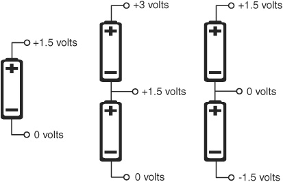
Figure 19-8 Separate cells may be tapped to derive several different voltages. Note that the ground connection is relative: when ground is the connection between batteries, you get both positive and negative voltages.
![]() With one cell you get the normal 1.5 volts.
With one cell you get the normal 1.5 volts.
![]() With two cells, you get 1.5 volts when tapping off the first cell, and 3 volts when tapping off the second cell.
With two cells, you get 1.5 volts when tapping off the first cell, and 3 volts when tapping off the second cell.
![]() The polarity of the voltage taps is relative. If you have a two-cell power supply, like that shown, the center tap can be made ground, or 0 volts. That means connecting to the negative terminal of the bottom cell actually provides a negative voltage cell, or −1.5 volts. The positive terminal of the top cell provides +1.5 volts.
The polarity of the voltage taps is relative. If you have a two-cell power supply, like that shown, the center tap can be made ground, or 0 volts. That means connecting to the negative terminal of the bottom cell actually provides a negative voltage cell, or −1.5 volts. The positive terminal of the top cell provides +1.5 volts.
Of course, you are not limited to tapping between single cells. If you have eight cells, for instance, you could tap at every other cell, and get voltages of 3, 6, 9, and 12 volts. Or you can combine two 6-volt battery packs to produce 6-and 12-volt supplies, or −6-and +6-volt supplies. These types of split supplies are useful in some kinds of motor connection schemes. See Chapter 22, “Using DC Motors,” for ideas.
Regulating Voltage
The parts of your robot may need specific voltages to operate properly. This is most often the case with electronics, which typically require 5 or 3.3 volts. The exact voltage can vary a bit, but not much. For example, on a 5-volt system, the acceptable voltage levels may be from 4.5 to 5.5 volts. No higher, no lower.
DC motors typically don’t require voltage regulation. Most run fine over a wide range of voltages. Increasing the voltage has the effect of making the motor run faster, and vice versa. R/C servo motors are an exception. Unless otherwise specified, they need to be operated at between around 4.5 and 7.2 volts.
Voltage regulation is accomplished in a number of ways. Here are the five most common; the first four are explained in more detail in this chapter.
![]() Silicon diodes can be used to drop the voltage in increments. This is not true regulation, but it can be used when all you need is a simple means to achieve a lower voltage. When put into a circuit, the typical silicon diode will reduce the voltage by about 0.7 volts.
Silicon diodes can be used to drop the voltage in increments. This is not true regulation, but it can be used when all you need is a simple means to achieve a lower voltage. When put into a circuit, the typical silicon diode will reduce the voltage by about 0.7 volts.
![]() Zener diodes clamp the voltage to a specific level and won’t let it get any higher.
Zener diodes clamp the voltage to a specific level and won’t let it get any higher.
![]() Linear voltage regulators, the most common variety, are cheap but relatively inefficient. In effect, they “step down” voltage from one level to another; the difference in voltage is dissipated as heat.
Linear voltage regulators, the most common variety, are cheap but relatively inefficient. In effect, they “step down” voltage from one level to another; the difference in voltage is dissipated as heat.
![]() Switching voltage regulators are more efficient—some boast up to 80 percent. They’re recommended over linear voltage regulators, but they may require more external components to implement in your designs. Many switching regulators can increase voltage—boost 3 volts to 5 volts, for example—as well as produce negative voltages from a positive voltage source.
Switching voltage regulators are more efficient—some boast up to 80 percent. They’re recommended over linear voltage regulators, but they may require more external components to implement in your designs. Many switching regulators can increase voltage—boost 3 volts to 5 volts, for example—as well as produce negative voltages from a positive voltage source.
![]() Modular DC-DC converters are self-contained voltage changers. Internally they use one or more switching regulators, and they also include all the additional components required. They’re more expensive.
Modular DC-DC converters are self-contained voltage changers. Internally they use one or more switching regulators, and they also include all the additional components required. They’re more expensive.
DROPPING VOLTAGE WITH SILICON DIODES
Diodes are the simplest of all semiconductors. A common use of diodes is to prevent current from flowing a certain direction in a circuit. Current will flow only in the “allowed” direction, but in doing this, there’s an inherent drop of voltage through the diode. For silicon diodes, the cheapest and most plentiful diode type, the voltage is reduced by about 0.7 volts.
Diodes don’t really “regulate” voltage; they only drop it by approximate amounts. Not all circuits need exact voltage regulation, but if yours does, one of the other methods is recommended instead.
What’s more, the actual voltage drop needs to be be measured when the diode is connected in line with the circuit. The drop increases as the current load increases. The highest drop is at the rated current for the diode.
You can use this effect to easily drop a voltage in increments of about 0.7 volts. Using one diode, a 6-volt power supply is reduced to about 5.3 volts (see Figure 19-9). That’s close enough to the +5 volts needed by most electronics. Using two diodes drops it down even further, to around 4.6 volts, and so on.
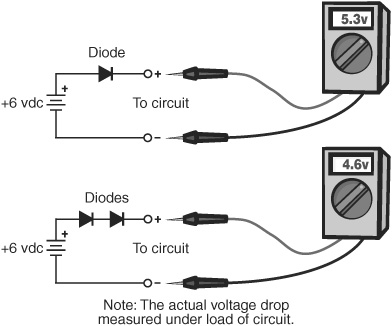
Figure 19-9 Diodes can be used to reduce the voltage to a circuit. Assuming silicon diodes, the voltage drop is about 0.7 volts. Combine diodes for higher voltage drops.
When selecting a diode for dropping voltage you need to also consider the current consumed by the circuit. Diodes are rated in amperes; pick a diode that can handle the current drawn by your circuit. The very common 1N4001 silicon diode can handle up to 1 amp, at 50 volts. The 1N5401 silicon diode handles up to 3 amps at 100 volts.
These types of diodes are often called rectifiers. Not all rectifier diodes are silicon. When in doubt, check the specs for the diode. Look at the cut-in or forward voltage drop specification. The voltage drop in most silicon diodes is about 0.7 volts; for Schottky and germanium diodes it’s around 0.3 volts. LEDs, a type of diode, exhibit even higher forward voltage drops. But these generally cannot handle much current, so they’re impractical as circuit voltage droppers.
ZENER DIODE VOLTAGE REGULATION
A quick and inexpensive method for providing a semiregulated voltage is to use zener diodes. A typical hookup diagram is shown in Figure 19-10. You can use zener regulation for circuits that don’t consume a lot of power—say, under an amp or two.
With a zener diode, current does not begin to flow through the device until the voltage exceeds a certain level. This level is called the breakdown voltage. Any voltage over this level is then “shunted” through the zener diode, effectively limiting the voltage to the rest of the circuit. Zener diodes are available in a variety of voltages, such as 3.3 volts, 5.1 volts, 6.2 volts, and others. A 5.1 zener is well suited for use on circuits needing a +5 volt supply.
Zener diodes are rated by their tolerance—1 percent and 5 percent are common. If you need tighter regulation, get the 1 percent kind.
They’re also specified by their power rating, expressed in watts. For low-current applications, a 0.25- or 0.5-watt zener should be sufficient; higher currents require larger 1-, 5-, and even 10-watt zeners. Note the resistor shown in Figure 19-10. It limits the current through the zener.
To calculate the value of this resistor, you need to know the maximum current draw of your circuit. You then do a bit of math:
1. Calculate the difference between the input voltage and the voltage rating of the zener diode. For example, suppose the input voltage is 7.2 volts, and you want to use a 5.1 volt zener:
7.2 − 5.1 = 2.1 volts
2. Determine the current draw of your circuit. You want to add an overhead margin of about 200 percent. If, for example, the circuit draws 100 mA (milliamps), then
0.1 × 2 = 0.2
In the preceding equation, 0.1 is 100 milliamps.
3. Determine the value of the resistor by dividing the current draw by the dropped-down voltage:
2.1 / 0.2 = 10.5 ohms
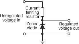
Figure 19-10 Zener diodes provide a simple form of voltage regulation. The value of the resistor depends on the incoming and regulated voltage levels and the amount of current the circuit is expected to draw. See the text on how to select the proper resistor value.
The nearest standard resistor value is 10 ohms, which is close enough.
4. Next, determine the wattage of the resistor. You do this by multiplying the difference in voltage from step 1, by the current draw of the circuit.
2.1 × 0.2 = 0.42 watts
Resistors are rated in watts and fractional watts: 1/8, 1/4, 1/2, 1, 2, and so on. Pick a resistor wattage at or above the calculated value. For this example, a 1/2-watt resistor will work.
5 Finally, determine the power dissipation for the zener diode. This is done by multiplying the current draw of the circuit by the voltage rating of the zener:
0.2 × 5.1 = 1.02 watts
You should use a zener rated at no less than 1 watt.
There is some simplification used in these calculation formulas—the reverse current of the zener is ignored, for example. But there are many approximations anyway, such as the overhead margin and use of standard component values. If you find your components get too hot, use a higher-wattage zener and resistor. If the voltage is too low, slightly decrease the value of the resistor.
LINEAR VOLTAGE REGULATION
Solid-state linear voltage regulators provide much more flexibility than zener regulators, and they’re relatively inexpensive—a few dollars at the most. They are easy to get at any electronics parts outlet, and you can choose from among several styles and output capacities.
Two of the most popular voltage regulators, the 7805 and 7812, provide +5 volts and +12 volts, respectively (other voltages are available—just change the last two digits). You connect them to the + (positive) and − (negative or ground) rails of your robot, as shown in Figure 19-11. In normal practice, you also place some capacitors across the input and output of the regulator. These act to smooth out any instantaneous fluctuations in the voltage.
The smallest linear regulators are provided in the small TO-92 transistor package (see Chapter 31 for more on this). In fact, they look just like small transistors. For the 7805 and 7812 regulators, and depending on the manufacturer, these are often identified with an “L” within the part number, for example, 78L05. The TO-92 regulators are limited to use in circuits drawing 100 mA or less of current.

Figure 19-11 A linear voltage regular requires no external parts, though it is customary (as good design) to include capacitors to help stabilize the voltage provided by the regulator.
More current is provided by regulators in the TO-220 style “power transistor” package. Use these when powering circuits that consume less than 500 milliamps. Other variations of the TO-220 style regulator can handle 1 amp or more. Check the datasheet that comes with the part you order.
![]()
Pinouts of voltage regulators can vary. Negative voltage regulators often have different pin assignments than positive voltage regulators. Reversing the connections to a voltage regulator will burn it out, so always double-check the datasheet for the device you are using. Always.
If you need more current, linear regulators are provided in larger TO-3 style transistor packages. They provide current outputs to several amps, depending on the exact device.
You can also get adjustable voltage regulators. These are some of the more common ones:
![]() The LM317T is an adjustable regulator in a TO-220 package. With some external parts (see its datasheet), you can adjust it to deliver from 1.2 volts to 37 volts, at a maximum of 1.5 amps.
The LM317T is an adjustable regulator in a TO-220 package. With some external parts (see its datasheet), you can adjust it to deliver from 1.2 volts to 37 volts, at a maximum of 1.5 amps.
![]() The LM317L offers the same voltage span, but is designed for use on circuits demanding 100 milliamps or less.
The LM317L offers the same voltage span, but is designed for use on circuits demanding 100 milliamps or less.
To enjoy the full current capacity of a voltage regulator you need to mount it on, or attach it to, a heat sink. Expect somewhat less current-carrying ability when a heat sink is not used.
Linear regulators require that the input be at least 1 volt, and usually 2 volts, over the expected output voltage. For example, for a 5-volt regulator, the unregulated supply should be about 2 volts higher, or 7 volts. By the same token, avoid applying too much voltage in relation to the output. The regulator throws off the extra voltage as heat, which is not only wasteful of energy but potentially harmful to the regulator. For that 5-volt regulator, the input voltage should be between 7 and 12 volts.
SWITCHING VOLTAGE REGULATION
Linear regulators take an incoming voltage and clamp it to some specific value. Linear regulation isn’t very efficient; as the voltage is stepped down to its desired level, excess energy (the difference between the input and output voltages) is wasted in the form of heat.
In AC-operated circuits this inefficiency is marginal, but it’s particularly notable in battery-powered systems, where battery life is limited.
Too, most linear regulators require a voltage source several volts higher than the expected output voltage. The difference is called voltage drop, and it’s why you need at least 7 volts to power a 5-volt circuit.
An alternative to linear regulators is the switching (or switching-mode) voltage regulator, which is more expensive but more efficient. Most high-tech electronics equipment uses switching power supplies. They’re common and not frightfully expensive.
A good example of a step-down switching voltage regulator is the MAX738, from Maxim. It comes in an 8-pin dual inline pin (DIP) IC package, among others; the DIP package is ideal for homebrew circuits. With just a few added parts you can build a simple, compact, and efficient voltage regulator. The output voltage is dependent on the external components that you use. Refer to the datasheet for the MAX738 for sample circuits.
Some kinds of switching voltage regulators can increase a lower voltage to a higher one. These are called step-up or boost regulators. One typical application is turning 3 volts from a pair of 1.5-volt alkaline cells into 5 volts, to run some microcontroller or other circuit. The Maxim MAX756 is a good example of a step-up switching regulator, able to turn any voltage from 1 to 5 volts into a regulated 5-volt output. Pretty nifty.
USING MULTIPLE VOLTAGE REGULATION
Not every subsystem in your robot will require the same voltage. Some parts might use 3.3 volts, while others use 5 volts. This requires that you use separate regulators for each voltage. Too, even if different subsystems require the same voltage, it’s not generally a good idea to power them all from the same regulator. In many cases, it’s better to use multiple regulators.
The concept of multiple regulation is simple, as shown in Figure 19-12. For each regulated subsystem you provide the regulator circuit. To prevent electrical noise from one subsystem from affecting another, be sure to add decoupling capacitors at each regulator. The capacitors effectively smooth out the voltage provided by the regulator, diminishing any instantaneous fluctuations in the power supply.
FYI
Read more about decoupling capacitors and how to use them, in Chapter 30, “Building Robot Electronics—the Basics.” But, in a nutshell, a decoupling capacitor is the name given to a capacitor that is used to help filter out electrical noise in a power supply. The capacitor is placed between the positive and ground connections of the power supply.

Figure 19-12 Use separate decoupling capacitors at the inputs and outputs of each separate voltage regulator used in your robot’s power system. For extra measure you can add decoupling capacitors at the outputs. Typical capacitor values to use are shown in Figure 19-11.
Dealing with Power Brownouts
You see, robots aren’t known to use power in an even, predictable manner. One moment the robot’s sitting still, using very little power, waiting for the right time to pounce on your poor unsuspecting cat. The next moment it’s screaming down the hall after the furry feline, burning amps like they’re going out of style.
Every time the motors kick in, a high amount of current is drawn from the batteries. This increase in current consumption can make the voltage delivered by the batteries momentarily dip. If these same batteries also supply the electronics in your robot, a condition called brownout, or sag, could occur.
As the battery voltage drops below that needed for the regulator, the electronics go into a brownout mode. They get enough power to stay on, but not enough for reliable operation. To avoid possible brownouts:
![]() Use separate batteries for the electronics and the motors. This is the single best way to avoid brownout problems. Use a small-capacity battery or pack for the electronics, and a pack with larger AA, C, or D cells for the motors. Note: To make this work, the ground leads of both battery supplies must be connected!
Use separate batteries for the electronics and the motors. This is the single best way to avoid brownout problems. Use a small-capacity battery or pack for the electronics, and a pack with larger AA, C, or D cells for the motors. Note: To make this work, the ground leads of both battery supplies must be connected!
![]() Use batteries with a higher per-cell voltage, to ensure enough overhead for proper voltage regulation. If you’re using NiCd or NiMH cells, for instance, which put out 1.2 volts per cell, switch to rechargeable alkaline. These produce 1.5 volts per cell.
Use batteries with a higher per-cell voltage, to ensure enough overhead for proper voltage regulation. If you’re using NiCd or NiMH cells, for instance, which put out 1.2 volts per cell, switch to rechargeable alkaline. These produce 1.5 volts per cell.
![]() Use one or more additional batteries to increase the voltage provided by the pack. Though nonstandard—and sometimes a bit hard to find—use a five-cell battery pack with your 1.2-volt NiCd or NiMH batteries. That increases the pack voltage from 4.8 volts to 6 volts.
Use one or more additional batteries to increase the voltage provided by the pack. Though nonstandard—and sometimes a bit hard to find—use a five-cell battery pack with your 1.2-volt NiCd or NiMH batteries. That increases the pack voltage from 4.8 volts to 6 volts.
![]() Power the electronics from a single 9-volt battery. Use appropriate voltage regulation, of course. The Arduino microcontroller boards have onboard regulation that will take the 9 volts input and provide the necessary 5 volts.
Power the electronics from a single 9-volt battery. Use appropriate voltage regulation, of course. The Arduino microcontroller boards have onboard regulation that will take the 9 volts input and provide the necessary 5 volts.
![]() Don’t let your batteries get so discharged that they can’t provide even the minimal operating current for your bot.
Don’t let your batteries get so discharged that they can’t provide even the minimal operating current for your bot.
![]() Design for lower-voltage electronics. Some microcontrollers operate at 3.3 volts.
Design for lower-voltage electronics. Some microcontrollers operate at 3.3 volts.
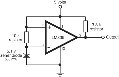
Figure 19-13 A voltage comparator and zener diode make for a convenient and easy-to-build battery-level monitor. You can adjust the trip point of the comparator—the input voltage at which its output changes—by experimenting with the value of the 10 kΩ resistor on the left.
Battery Voltage Monitors
Quick! What’s the condition of the battery in your robot? With a battery monitor, you’d know in a flash. A battery monitor continually samples the output voltage of the battery during operation of the robot (the best time to test the battery) and provides a visual or logic output. A microcontroller-compatible battery monitor is shown in Figure 19-13. This monitor uses a 5.1-volt half-watt zener as a voltage reference alone with an LM 339 quad comparator IC. Only one of the comparator circuits in the IC is used; you are free to use any of the remaining three for other applications.
The circuit is set to trip when the voltage sags below the (approximate) 5-volt threshold of the zener (in my test circuit the comparator tripped when the supply voltage dipped to under 4.5 volts). When this happens, the output of the comparator immediately drops to 0 volts.