
Chapter 23
Using Servo Motors
DC motors are inherently an open feedback system—you give them juice, and they spin. How much they spin is not always known, at least not without additional mechanical and electronic parts.
Servo motors, on the other hand, are a closed feedback system. This means the output of the motor is coupled to a control circuit. As the motor turns, the control circuit monitors the position. The circuit won’t stop the motor until the motor reaches its proper point. All without your having to do anything extra.
Servo motors have earned an important place in robotics. And fortunately for robot builders, another hobby—model radio control—has made these motors plentiful, easy to use, and quite inexpensive.
In this chapter you will learn what you need to know to use radio control (R/C) servos in your robot projects. While there are other types of servo motors, it is the R/C type that is commonly available and affordable, so I’ll be sticking with those only.
FYI
Be sure to also check out Chapter 24, “Mounting Motors and Wheels,” to learn how to attach servos to your bot, and the chapters in Part 7, “Microcontroller Brains,” on how to program servos to do various wonderful things.
How R/C Servos Work
Servo motors designed to be operated via a radio-controlled link are commonly referred to as radio-controlled (or R/C) servos, though, in fact, the servo motor itself is not what’s radio controlled. The motor is merely connected to a radio receiver on the model plane or car. The servo takes its signals from the receiver.
This means you don’t need to control your robot via radio signals just to use an R/C servo (unless you want to, of course). You can control a servo with your PC, a microcontroller such as the Arduino.
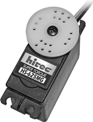
Figure 23-1 A standard-size servo motor for radio-controlled model airplanes and cars. The flanges allow easy mounting, and the output of the servo can be readily attached to wheels, linkages, and other mechanisms. (Photo courtesy Hitec RCD.)
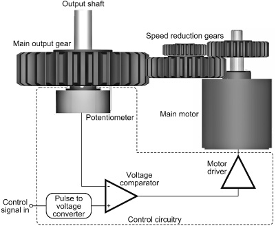
Figure 23-2 How an RC servo works. A control signal causes the motor to turn in one direction or the other, depending on the current position of the output shaft.
Figure 23-1 shows a typical standard-size R/C servo motor, which is used with model flyable airplanes and model racing cars. It measures about 1-1/2″ × 3/4″ × 1-3/8″. For this style of servo, its size and the way it’s mounted are the same, regardless of the manufacturer. That means that you have your pick of a variety of makers and can compare prices. There are other common sizes of servo motors besides that shown in the figure, however. I’ll get to those in a bit.
A PEEK INSIDE
Inside the servo is a motor and various other components, neatly packaged (see Figure 23-2). While not all servos are exactly alike, all have these three major parts: motor, reduction gear, and control circuitry.
![]() Motor. A DC motor capable of reversing direction is at the heart of the servo.
Motor. A DC motor capable of reversing direction is at the heart of the servo.
![]() Reduction gears. The high-speed output of the motor is reduced by a gearing system. Many revolutions of the motor equal one revolution of the output gear and shaft of the servo.
Reduction gears. The high-speed output of the motor is reduced by a gearing system. Many revolutions of the motor equal one revolution of the output gear and shaft of the servo.
![]() Control circuitry. The output gear is connected to a potentiometer, a common electronic device similar to the volume control on a radio. The position of the potentiometer indicates the position of the output gear.
Control circuitry. The output gear is connected to a potentiometer, a common electronic device similar to the volume control on a radio. The position of the potentiometer indicates the position of the output gear.
The motor and potentiometer are connected to a control board, all three of which form a closed feedback loop. The servo is powered by 4.8 to 7.2 volts.

You can’t run an R/C servo simply by connecting it to a battery. It needs special control signals to operate. As it turns out, it’s not terribly hard to control a servo using simple programming. Numerous programming examples are provided in Part 7.
LIMITING ROTATION
As you can surmise, servo motors are designed for limited rotation rather than for continuous rotation like a DC motor. While there are servos that rotate continuously, and you can modify one to freely rotate (see later in this chapter), the primary use of the R/C servo is to achieve accurate rotational positioning over a range of up to 180°.
While 180°—half a circle—may not sound like much, in actuality such control can be used to steer a robot, move legs up and down, rotate a sensor to scan the room, and more. The precise angular rotation of a servo in response to a specific digital signal has enormous uses in all fields of robotics.
Control Signals for R/C Servos
The control signal that commands a servo to move to a specific point is in the form of a steady stream of electrical pulses. The exact duration of the pulses, in fractions of a millisecond (one-thousandths of a second), determines the position of the servo, as shown in Figure 23-3.
Note that it is not the number of pulses per second that controls the servo, but the duration of the pulses that matters. This is very important to fully understand how servos work and how to control them with a microcontroller or other circuit.
Specifically, the servo is set at its center point if the duration of the control pulse is 1.5 milliseconds. Durations longer or shorter command the servo to turn in one direction or the other.
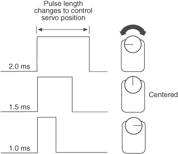
Figure 23-3 The length of the control pulses determines the angular position of the servo shaft. The pulse range is from 1.0 millisecond (or 1000 microseconds) to 2.0 ms (2000 μs). A pulse of 1.5 ms (1500 μs) positions the servo shaft in the middle.
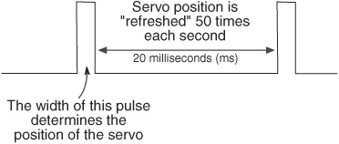
Figure 23-4 Control pulses are repeated (“refreshed”) at roughly 50 Hz (50 times each second).
![]() A duration of 1.0 milliseconds (ms) causes the servo to turn all the way in one direction.
A duration of 1.0 milliseconds (ms) causes the servo to turn all the way in one direction.
![]() A duration of 2.0 ms causes the servo to turn all the way in the other direction.
A duration of 2.0 ms causes the servo to turn all the way in the other direction.
![]() And to recap, a duration of 1.5 ms causes the servo to return to its midpoint.
And to recap, a duration of 1.5 ms causes the servo to return to its midpoint.
The servo needs about 30 to 50 of these pulses per second, as shown in Figure 23-4. This is referred to as the refresh (or frame) rate; if the refresh rate is too low, the accuracy and holding power of the servo are reduced. If there are way too many pulses per second, the servo may jitter and fail to work properly.
PULSES ALSO CONTROL SPEED
As mentioned, the angular position of the servo is determined by the duration of the pulse. This technique has gone by many names over the years. One you may have heard is digital proportional—the movement of the servo is proportional to the digital signal being fed into it.
The power delivered to the motor inside the servo is also proportional to the difference between where the output shaft is and where it’s supposed to be. If the servo has only a little way to move to its new location, then the motor is driven at a fairly low speed. This ensures that the motor doesn’t “overshoot” its intended position.
But if the servo has a long way to move to its new location, then it’s driven at full speed in order to get it there as fast as possible. As the output of the servo approaches its desired new position, the motor slows down.
People often refer to the pulses used to control an R/C servo as pulse width modulation, or PWM. That’s okay, but it can lead to some confusion.
Technically speaking, R/C servos employ what might be better termed pulse duration modulation. With PWM (detailed in Chapter 22, “Using DC Motors”), it’s the duty cycle of the pulses—the ratio that each pulse is on versus off—that matters. R/C servos don’t care about duty cycles or ratios. All they care about is how long the pulse is. As long as the servo receives at least 20 of these pulses per second (50 is better), it’s happy.
You can call whatever goes on inside a servo anything you like, just as long as you remember that a PWM signal for a DC motor bears no relation to the “PWM” signal used to control an R/C servo. In fact, trying to use a PWM signal intended for a DC motor will likely overheat and damage an R/C servo.
VARIATION IN PULSE WIDTH RANGES
Most standard servos are designed to rotate back and forth by 90° to 180°, given the full range of timing pulses. You’ll find the majority of servos will be able to turn a full 180°, or very nearly so.
The actual length of the pulses used to position a servo to its full left or right positions varies among servo brands, and sometimes even among different models by the same manufacturer. You need to do some experimenting to find the optimum pulse width ranges for the servos you use. This is just part of what makes robot experimenting so much fun!
The 1-to-2-ms range has built-in safety margins to prevent possible damage to the servo. Using this range provides only about 100° of turning, which is fine for many tasks.
But if you want a full stop-to-stop rotation, you need to apply pulses shorter and longer than 1 to 2 ms. Exactly how long depends entirely on your specific servo. Full rotation (to the stop) for one given make and model of servo might be 0.730 ms in one direction and 2.45 ms in the other direction.
You must be very careful when using shorter or longer pulses than the recommended 1-to-2-ms range. Should you attempt to command a servo beyond its mechanical limits, the output shaft of the motor will hit an internal stop, which could cause gears to grind or chatter. If left this way for more than a few seconds, the gears may be permanently damaged.
The 1.5 ms “in-between” pulse may also not precisely center all makes and models of servos. Slight electrical differences even in servos of the same model may produce minute differences in the centering location.
Timing signals for R/C servos are often stated in milliseconds, but a more accurate unit of measure is the microsecond—or millionth of a second. In the programming chapters that follow you’ll more often see timing pulses for servos stated in microseconds.
To convert milliseconds to microseconds, just move the decimal point to the right three digits. For example, if a pulse is 0.840 milliseconds, move the decimal point over three digits and you have 0840, or 840 microseconds (lop off the leading zero; it’s not needed).
The Role of the Potentiometer
The potentiometer of the servo plays a key role in allowing the motor to set the position of its output shaft, so it deserves a short explanation of its own.
The potentiometer is mechanically attached to the output shaft of the servo (in some servo models, the potentiometer is the output shaft). In this way, the position of the potentiometer very accurately reflects the position of the output shaft of the servo.
The control circuit in the servo compares the position of the potentiometer with the pulses you feed into the servo. The result of this comparison is an error signal. The control circuitry compensates by moving the motor inside the servo one way or the other. When the potentiometer reaches its final proper position, the error signal disappears and the motor stops.
Special-Purpose Servo Types and Sizes
While the standard-size servo is the one most commonly used in both robotics and radio-controlled models, other R/C servo types, styles, and sizes also exist.
![]() Quarter-scale (or large-scale) servos are about twice the size of standard servos and are significantly more powerful. Quarter-scale servos make perfect power motors for a robot arm.
Quarter-scale (or large-scale) servos are about twice the size of standard servos and are significantly more powerful. Quarter-scale servos make perfect power motors for a robot arm.
![]() Mini- and micro servos are diminutive versions of standard servos and are designed to be used in tight spaces in a model airplane or car—or robot. They aren’t as strong as standard servos.
Mini- and micro servos are diminutive versions of standard servos and are designed to be used in tight spaces in a model airplane or car—or robot. They aren’t as strong as standard servos.
![]() Sail winch servos are designed with maximum strength in mind and are primarily intended to move the jib and mainsail sheets on a model sailboat.
Sail winch servos are designed with maximum strength in mind and are primarily intended to move the jib and mainsail sheets on a model sailboat.
See the “Typical Servo Specifications” table, later in this chapter, for a size comparison of these various types.
Gear Trains and Power Drives
The motor inside an R/C servo turns at several thousand RPMs. This is way too fast to be used directly; all servos employ a gear train that reduces the output of the motor to the equivalent of about 50 to 100 RPM. Servo gears can be made of nylon, metal, or a proprietary material.
![]() Nylon gears are the lightest and least expensive to make. They’re fine for general-purpose servos.
Nylon gears are the lightest and least expensive to make. They’re fine for general-purpose servos.
![]() Metal gears are much stronger than nylon and are used where brute-force power is needed, but they significantly raise the cost of the servo. They’re recommended for heavier walking robots or large robotic arms. On many servos only some of the gears are metal; the rest are a heavy-duty nylon or other plastic material.
Metal gears are much stronger than nylon and are used where brute-force power is needed, but they significantly raise the cost of the servo. They’re recommended for heavier walking robots or large robotic arms. On many servos only some of the gears are metal; the rest are a heavy-duty nylon or other plastic material.
![]() Gears made of proprietary materials include Karbonite, found on Hitec servos. These materials are offered as stronger alternatives to plastic.
Gears made of proprietary materials include Karbonite, found on Hitec servos. These materials are offered as stronger alternatives to plastic.
Replacement gear sets are available for many servos, particularly the medium- to high-priced ones ($20+). Should one or more gears fail, the servo can be disassembled and the gears replaced.
Output Shaft Bushings and Bearings
Besides the drive gears, the output shaft of the servo receives the most wear and tear. On the least expensive servos this shaft is supported by a plastic or resin bushing, which obviously can wear out very quickly if the servo is used heavily. A bushing is a one-piece sleeve or collar that supports the shaft against the casing of the servo.
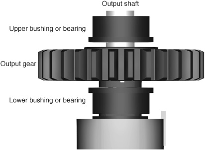
Figure 23-5 Ball bearings or bushings may be placed at the bottom and/or top of the servo output gear, in order to prolong the life of the servo motor.
Metal bushings, typically made from lubricant-impregnated brass (often referred to as Oilite, a trade name), last longer but add to the cost of the servo. The better servos come equipped with ball bearings, which provide longest life.
When looking at servos, you’ll often see a notion regarding the bearing type, either bushing or bearing, and whether it’s metal or plastic. You also may see a notation for “Top” or “Bottom”; this refers to having a bushing or bearing on the top and/or bottom of the output gear (top and bottom is best), like that shown in Figure 23-5.
Typical Servo Specs
R/C servo motors enjoy some standardization. This sameness applies primarily to standardized servos, which measure approximately 1.6″; × 0.8″ × 1.4″. For other servo types the size varies somewhat among makers, as these are designed for specialized tasks.
Table 23-1 outlines typical specifications for several types of servos, including dimensions, weight, torque, and transit time. Of course, except for the size of standard servos, these specifications can vary according to brand and model. Keep in mind that there are variations on the standard themes for all R/C servo classes.
A couple of the terms used in the specs require extra discussion.
![]() As explained in Chapter 21, “Choosing the Right Motor,” the torque of the motor is the amount of force it exerts. Servos exhibit very high torque thanks to their internal gearing.
As explained in Chapter 21, “Choosing the Right Motor,” the torque of the motor is the amount of force it exerts. Servos exhibit very high torque thanks to their internal gearing.
![]() The transit time (also called slew rate) is the approximate time it takes for the servo to rotate the shaft a certain number of degrees, usually 60°. The faster the transit time, the faster-acting the servo will be.
The transit time (also called slew rate) is the approximate time it takes for the servo to rotate the shaft a certain number of degrees, usually 60°. The faster the transit time, the faster-acting the servo will be.
You can calculate equivalent RPM by multiplying the 60° transit time by 6 (to get full 360° rotation), then dividing the result into 60. For example, if a servo motor has a 60° transit time of 0.20 seconds, that’s one revolution in 1.2 seconds (0.2 × 6 = 1.2), or 50 RPM (60/1.2 = 50).
Table 23-1 Typical Servo Specifications

Connector Styles and Wiring
While some servo specifications may vary from one model to another, one thing that’s much more standardized is the connectors used to plug servos into their receivers.
CONNECTOR TYPE
There are three primary connector types found on R/C servos:
![]() “J” or Futaba style
“J” or Futaba style
![]() “S” or Hitec/JR style
“S” or Hitec/JR style
![]() “A” or Airtronics style
“A” or Airtronics style
Servos made by the principal servo manufacturers—Futaba, Airtronics, Hitec, and JR—employ the connector style popularized by that manufacturer. In addition, servos made by competing manufacturers are usually available in a variety of connector styles, and connector adapters are available.
PINOUT
The physical shape of the connector is just one consideration. The wiring of the connectors (called the pinout) is also critical. Fortunately, all but the “old-style” Airtronics servos (and the occasional oddball four-wire servo) use the same pinout, as shown in Figure 23-6.
With very few exceptions, R/C servo connectors use three wires, providing ground, DC power (+V), and signal. The +V DC power pin is virtually always in the center; that way, if you manage to plug the servo in backward, there’s less chance of damage. (An exception to this is what’s referred to as “old-style Airtronics,” a wiring scheme no longer in use. You may encounter it if you have some older-model Airtronics servos.)
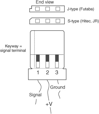
Figure 23-6 Standard three-pin connector used on the vast majority of RC servo motors. The connector may or may not be “keyed” using a groove or notch.
COLOR CODING
Most servos use color coding to indicate the function of each connection wire, but the actual colors used for the wires vary among servo makers. Some of the more common wire color coding is::
![]() White, orange, or yellow: Signal
White, orange, or yellow: Signal
![]() Red: +V (DC power)
Red: +V (DC power)
![]() Black or brown: Ground
Black or brown: Ground
USING SNAP-OFF HEADERS FOR MATED CONNECTORS
R/C servos and their mating receivers use polarized connectors to help prevent plugging things in back-ward. These polarized connectors are fairly expensive, and most folks instead use 0.100″ “snap-off” pin headers, common in electronics. You can buy these things at any local or online electronic parts outlet, and they’re pennies a piece.
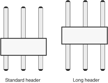
Figure 23-7 A standard male header, versus one that uses long pins on both ends. You want the long-pin version to connect your RC servos to a solderless breadboard.
For a servo, snap off three pins, then solder them to your circuit board. Since these header pins lack any kind of polarization, it’s possible to plug servos in backward. You’ll want to mark how the servo connector should attach to the header, to help prevent this.
Fortunately, reversing the connector probably won’t cause any damage to either the servo or the electronics, since reversing the connector merely exchanges the signal and ground wires. This is not true of the “old-style” Airtronics connector: if you reverse this connector, the signal and DC power (+V) lines are swapped. In this case, both servo and control electronics can be irreparably damaged.
![]()
Damage can and will occur if you wire up the pin headers wrong. Mix up the Ground and +V pins, and within seconds your servo will be permanently ruined—perhaps even die a violent death. I’ve seen the bottoms of servos blown out when they have been connected backward in a circuit.
You can also use headers with solderless breadboards to easily and quickly connect servo motors to the rest of your robot electronics, but it works best if you use the kind of header where the pins are long on both ends (Figure 23-7).
Analog versus Digital Servos
The most common, and most affordable, R/C servos are analog, meaning their control electronics uses traditional circuitry for controlling the motor. Digital servos use onboard micro-controllers to enhance their operation.
Among the added features of digital servos include higher-power and programmable behavior. With the proper external programmer (available separately, and at extra cost) it’s possible to control the maximum speed of the servo, for example, or make the servo always start from power-up in a specific position.
Except for higher torques, from an applications standpoint there is little difference between analog and digital servos. You control both the same way. However the higher torque of a digital servo means the motor is drawing more current from its power source, which means batteries tend not to last as long between charges.
For most robotics applications, digital servos are not required. You can get by with the less expensive standard analog servos. An exception is when building a walking robot, where the extra torque of digital servos comes in handy. Six-legged walking bots may use 12 and even 18 servos just for the legs. The higher torque helps to offset the added weight of all those servos.
Electronics for Controlling a Servo
Unlike a DC motor, which runs if you simply attach a battery to it, a servo motor requires proper interface electronics in order to rotate its output shaft. While the need for interface electronics may complicate to some degree your use of servos, the electronics are actually rather simple. And if you plan on operating your servos with a PC or microcontroller (such as the Arduino, PICAXE, or BASIC Stamp), all you need for the job is a few lines of software.
A DC motor typically needs power transistors, MOSFETs, or relays if it is interfaced to a computer. A servo, on the other hand, can be directly coupled to a circuit or microcontroller with no additional electronics. All of the power-handling needs are taken care of by the control circuitry in the servo, saving you the hassle. This is one of the key benefits of using servos with computer-controlled robots.
CONTROLLING A SERVO VIA A MICROCONTROLLER
All microcontrollers can be used to control an R/C servo. The basic connection scheme is shown in Figure 23-8.
![]() The microcontroller and servo can share the same power source, assuming the controller has an onboard regulator, but it’s much better to use a separate source for the servo. Why? Servos draw a lot of current when they’re first turned on or are in motion. By using separate sources—a 9-volt battery for the voltage-regulated controller, for example, and a set of 4 AA cells for the servo—you avoid messy power line problems.
The microcontroller and servo can share the same power source, assuming the controller has an onboard regulator, but it’s much better to use a separate source for the servo. Why? Servos draw a lot of current when they’re first turned on or are in motion. By using separate sources—a 9-volt battery for the voltage-regulated controller, for example, and a set of 4 AA cells for the servo—you avoid messy power line problems.
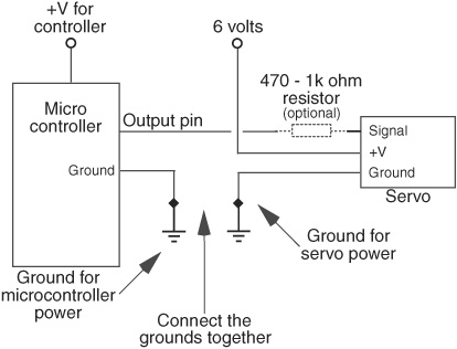
Figure 23-8 General connection diagram for attaching a microcontroller to a servo motor. The 470 to 1 kΩ resistor is optional, and is included to prevent excessive current draw by the servo.
![]() When using separate power sources, be sure to connect the grounds from these sources together. Otherwise, your server will not work properly.
When using separate power sources, be sure to connect the grounds from these sources together. Otherwise, your server will not work properly.
![]() Only one input/output (I/O) line from the microcontroller is needed to operate the servo. You may insert an optional 470 Ω (ohm) 1/8-watt resistor inline between the controller and the Signal input of the servo. This helps protect the microcontroller in case the servo has an (unlikely) internal electrical problem.
Only one input/output (I/O) line from the microcontroller is needed to operate the servo. You may insert an optional 470 Ω (ohm) 1/8-watt resistor inline between the controller and the Signal input of the servo. This helps protect the microcontroller in case the servo has an (unlikely) internal electrical problem.
Be sure to power the servos using a separate battery pack. Connect as shown. You might also wish to add a 1 μF to 22 μF tantalum capacitor between the +V and ground of the servo power source to help kill any noise that may be induced into the electronics when the servo turns on and off.
Tantalum capacitors are polarized. Be sure to connect the + lead of the capacitor to the +V pin of the servo. For more information about tantalum and other types of capacitors, see Chapter 31, “Common Electronic Components for Robotics.”
FYI
See the chapters in Part 7, “Microcontroller Brains,” for specific hookup diagrams and programming code for using servos with the Arduino and other microcontrollers. Be sure to also visit the RBB Online Support site (see Appendix A) for additional programming examples.
USING A SERIAL SERVO CONTROLLER
Even the fastest microcontrollers have trouble generating signals for more than 8 or 10 servos at a time—and you may have that many, or more!, if you’ve designed a six-legged walking robot.
Even if your microcontroller is a speed demon and has no trouble creating pulses for 12, 18, or even 24 servos, you may not want to use it for that task. Instead, you may wish to use a dedicated serial servo controller. It acts as a pulse-making coprocessor.
Servo controllers connect to your microcontroller via a serial communications line. Using programming code (examples are provided with the unit you buy), you then send commands to each servo, telling it to move to a certain position. The work of producing the properly timed pulses is the job of the servo controller, thus freeing up your microcontroller to do other, more important jobs.
BONUS PROJECT: CONTROLLING A SERVO VIA AN LM555 TIMER IC, AND MORE
See the RBB Online Support site for additional methods of controlling an R/C servo, including using an LM555 timer IC, practical examples of using several popular serial servo controllers (like the Lynxmotion SSC-32), and more. See Appendix A for details on how to access the RBB Online Support site.
USING GREATER THAN 7.2 VOLTS
Servos are designed to be used with rechargeable model R/C battery packs, which put out from 4.8 to 7.2 volts, depending on the number of cells they have. Servos allow a fairly wide latitude in input voltage, and 6 volts from a four-pack of AAs provides more than enough juice. As the batteries drain, however, the voltage will drop, and you will notice your servos won’t be as fast or strong as they used to be.
But what about going beyond the voltage of typical rechargeable batteries used for R/C models? Indeed, some servos can be operated at 7.2 volts, but always check the datasheet that comes with the servos you are using. Unless you need the extra torque or speed, it’s best to keep the supply voltage to your servos at no more than 7.2 volts, and preferably between the rated 4.8- to 6-volt range specified in the manufacturer’s literature.
WORKING WITH AND AVOIDING THE “DEAD BAND”
References to the Grateful Dead notwithstanding, all servos exhibit what’s known as a dead band. The dead band of a servo is the maximum time difference between the incoming control signal and the internal reference signal produced by the position of the potentiometer. If the difference equates to less than the dead band—say, 5 or 6 microseconds—the servo will not bother trying to nudge the motor to correct for the error.
Without the dead band, the servo would constantly “hunt” back and forth to find the exact match between the incoming signal and its own internal reference signal. The dead band allows the servo to minimize this hunting so it will settle down to a position close to, though maybe not exactly, where it’s supposed to be.
The dead band amounts vary and are often listed as part of the servo’s specifications. A typical dead band is 5 μs. If the servo has a full travel of 180° over a 1000-μs range, then the 5-μs dead band equates to 1 part in 200. If your control circuitry has a resolution higher than the dead band, then small changes in the pulse width values may not produce any effect. For instance, if the controller has a resolution of 2 μs, and if the servo has a dead band of 5 μs, you must make changes in the pulse width in no less than 5-μs increments.
Using Continuously Rotating Servos
So far I’ve only talked about servos that are meant to turn a portion of a circle. These are used when precise angular positioning is required, such as scanning a sensor from side to side.
But R/C servos can also rotate continuously, either by design or via a modification that you perform yourself. R/C servos make terrific drive motors for your robot. They tend to be less expensive than comparable DC gear motors of the same specification, and they come with their own driver electronics. They’re definitely worth considering for your next robot.
Servos that rotate continuously act like an ordinary geared DC motor, except they’re still controlled by sending the motor pulses.
![]() To make the motor go in one direction, send it 1 ms pulses.
To make the motor go in one direction, send it 1 ms pulses.
![]() To make the motor go in the other direction, send it 2 ms pulses.
To make the motor go in the other direction, send it 2 ms pulses.
![]() To make the motor slow to a stop, send it 1.5 ms pulses.
To make the motor slow to a stop, send it 1.5 ms pulses.
![]() To make the motor stop altogether, stop sending it pulses.
To make the motor stop altogether, stop sending it pulses.
Stopping the motor by ceasing the pulses works for all except digital servos. With most digital servos, when pulses are stopped the servo will merely continue with the last good position information it received.
You’re not likely to use digital servos for continuous rotation, so this problem seldom comes up in real life. But keep it in mind just in case.
As of this writing, there’s just a small handful of servos made for continuous rotation. These include the GWS S-35, the Parallax Continuous Rotation Servo, and the SpringRC SM-S4303R. These are available from a variety of online resellers; see Appendix B, “Internet Parts Sources,” for more information.
Modifying a Standard Servo for Continuous Rotation
You can convert most any servo to continuous rotation. Once modified, they no longer are capable of precise angular rotation, but they’re perfectly suited as drive motors for wheeled and tracked bots.
There are a number of methods you can use to modify an R/C servo for continuous rotation. The process involves removing the mechanical stops, and—for some types of servo surgery—making a change in the electrical connections inside.
WAYS TO MODIFY A SERVO
There are many ways to modify R/C servos. In reverse order of difficulty:
![]() Power-train mod. For this modification, the control electronics are removed completely, and the motor is driven by an external H-bridge. Any stops are removed from the power train, and the potentiometer is either removed or its shaft is otherwise disengaged from the servo drive. This is a lot of work, and most people don’t bother.
Power-train mod. For this modification, the control electronics are removed completely, and the motor is driven by an external H-bridge. Any stops are removed from the power train, and the potentiometer is either removed or its shaft is otherwise disengaged from the servo drive. This is a lot of work, and most people don’t bother.
![]() Signal tap-in mod. In this conversion the electronics of the servo remain, but, as usual, the mechanical stops are removed and the potentiometer is disengaged. In this variation, the robot’s computer or microcontroller is connected to the H-bridge chip within the servo’s circuitry. Not all servos are so adaptable, however. Several Internet sites detail this tapping-in process for the BAL6686 H-bridge IC, used in certain Futaba models and other servos. Do a Web search for “BAL6686” for a number of useful sites that describe this.
Signal tap-in mod. In this conversion the electronics of the servo remain, but, as usual, the mechanical stops are removed and the potentiometer is disengaged. In this variation, the robot’s computer or microcontroller is connected to the H-bridge chip within the servo’s circuitry. Not all servos are so adaptable, however. Several Internet sites detail this tapping-in process for the BAL6686 H-bridge IC, used in certain Futaba models and other servos. Do a Web search for “BAL6686” for a number of useful sites that describe this.
![]() Potentiometer mod. Here all the control circuitry is left in place, but the potentiometer is either removed completely (and replaced with a couple of resistors) or disengaged from the power train. This is the easiest modification to make, and the most popular.
Potentiometer mod. Here all the control circuitry is left in place, but the potentiometer is either removed completely (and replaced with a couple of resistors) or disengaged from the power train. This is the easiest modification to make, and the most popular.
Of these methods I’ll talk only about the last one, as the others have far more restricted uses and are much more difficult. The potentiometer mod that follows is relatively quick and easy, requires no soldering, and needs basic basic tools.
BASIC MODIFICATION INSTRUCTIONS
Servo modification varies somewhat among makes and models, but the basic steps are the same:
1. Remove the case of the servo to expose the gear train, motor, and potentiometer. This is accomplished by removing the four screws on the servo case and separating the top and bottom.
2. File or cut off the nub on the underside of the output gear that prevents full rotation. This typically means removing one or more gears, so you should be careful not to misplace any parts. If necessary, make a drawing of the gear layout so you can replace things in their proper location.
3. Remove the retainer clip at the bottom of the output gear. Doing this disengages the potentiometer from the gear, so that the pot no longer turns when the gear does. On some servos there is no retainer clip; the servo engages into a spline molded into the bottom of the gear. On these you need to carefully drill out the bottom of the gear.
4. Reassemble the case.
In the following section you’ll find detailed modification instructions for the Hitec HS-422—the same instructions apply to many other servos, such as the venerable Futaba S-148 and the GWS S03. With the same or minor variations, the steps that follow can be applied to similarly designed servos.
TOOLS YOU NEED
You’ll need the following tools to complete the conversion process:
![]() #0 Phillips screwdriver
#0 Phillips screwdriver
![]() 1/8″ or smaller flat-bladed screwdriver
1/8″ or smaller flat-bladed screwdriver
![]() “Nippy”: cutters, X-Acto blade, or razor saw
“Nippy”: cutters, X-Acto blade, or razor saw
![]() Small, flat jeweler’s file
Small, flat jeweler’s file
CHOOSING A SERVO TO MODIFY
The best servos, from a standpoint of easy modification:
Use a lower ball bearing or bushing that supports the output gear. At the very least, the output gear should be supported by a molded-in ledge, rather than directly on the potentiometer shaft.
Use a removable potentiometer shaft clip. The clip can be readily removed in order to disengage the output gear from the potentiometer shaft. Servos that lack a removable clip will use instead a molded-in channel that the potentiometer fits into. This is the case of the Hitec HS-311 and the Futaba S-3003. If your servo is so constructed, you’ll need to carefully drill out the bottom of the output gear in order to remove the spline, as detailed later in this chapter.
Use a plastic output gear, rather than a metal gear. The better, heavy-duty servos use a metal output gear. While the metal is able to handle increased stress, it’s significantly harder to modify. If your servo of choice uses a metal output gear, a motorized hobby tool such as the Dremel will make the job of grinding down the nub much easier.
Are normal sized or larger. Mini and micro servos are more difficult to modify. You may ruin one or two before you get the hang of it.
STEPS FOR MODIFYING A HITEC HS-422
The Hitec HS-422 is a good middle-of-the-road servo: low price, available anywhere, and well made. It employs both a top and bottom oil-impregnated brass bushing and a removable clip on the underside of the output gear. Perfect!
Throughout the following, use care to avoid wiping off or absorbing through your skin too much of the lubricant used for the internal gears of the servo. If you think lubrication has been lost, you can always add more just prior to reassembly. Clear (or white) gear grease is available at any hobby store that sells R/C parts. Apply the grease sparingly. Do not use a spray-on lubricant such as WD-40.
Before performing the modification, test the servo for proper operation, just to be sure it’s not bad to begin with. Though rare, some servos fail to work right out of the box. Once it is modified, you cannot return the servo for in-warranty replacement.
1. Using a Phillips screwdriver, remove the horn wheel, if one is attached to the servo.
2. Untighten the four casing screws from the bottom of the servo. If they don’t get in the way in the following steps, you can keep the screws in place in the bottom of the case. Unscrew just enough to remove the top of the servo case. Note that on a few servos, notably the S03 series from GWS, the case screws are removed from the top, and these should be removed all the way and set aside while you work.

3. Observe the orientation of all the gears. Remove the center gear, being careful not to unseat its metal shaft. On most servos the center gear cannot be easily removed without also lifting up the output gear at the same time. Place the center gear aside.
![]()
4. Remove the output gear.
5. Using nippy cutters, X-Acto blade, or razor saw, remove the nub on the top side of the output gear. I prefer the cutters, but exercise caution! The harder the plastic, the more likely the nub will break off at high speed. Wear eye protection. Always nip first on the long side, to prevent possible breakage of the gear, and cut off only a small portion at a time. When using an X-Acto blade or razor saw, the obvious precautions against cutting your fingers off should be observed. Work slowly.

6. Odds are, no matter what cutting technique you use, a small portion of the nub will remain. This can be filed down with a small flat file.

7. Use the small-bladed screwdriver to remove the metal retaining ring from the underside of the output gear. This ring retains the potentiometer shaft clip and also serves as a bearing surface.
8. Use the small-bladed screwdriver to remove the retaining clip.
9. Replace the metal retaining ring back into the output gear.

10. Align the potentiometer shaft so that it’s centered. If needed, rotate it back and forth to find the center.
11. As an optional step, you may want to connect the servo to your control circuit. Apply 1.5 ms (1500 μs) pulses. If the motor turns (even slowly), rotate the potentiometer shaft until all rotation is “nulled out.”
![]()
12. Once set to its center, you can leave the shaft as is or apply a very small dab of cyanoacrylate glue (Super Glue) to keep the shaft in place. Do not apply too much glue, or the potentiometer may be damaged.
13. Reassemble by placing the output gear on its seat over the potentiometer. Replace the middle gear, and observe that all gears properly mesh. Add more grease at this point, if needed. Finally, replace the top case and the four case screws. Don’t overtighten the screws.
Test the servo for proper operation by connecting it to your control circuit. A series of 1.5 ms pulses should stop the servo. A signal of 1.0 ms pulses should rotate the servo in one direction; 2.0 ms pulses should rotate the servo in the other direction.
These steps are virtually the same for several other popular low-cost servos, including the Futaba S-148, and the S03 series of servos from GWS.
STEPS FOR MODIFYING A FUTABA S3003 SERVO
The Futaba S3003 is a low-cost alternative to servos with metal bushing or ball bearings. As with many servos of its type, it doesn’t use a retained clip for the potentiometer. You need to drill out the bottom of the gear so that the gear will no longer engage with the potentiometer.
1. Follow steps 1 through 6, above.
2. Using a spare servo horn (the larger, the better), attach the horn to the output gear using the mounting screw provided with the servo.
3. For steps 7 though 9, instead, carefully drill out the bottom of the output gear with a 3/16″ (or thereabouts) drill bit. Remove as much of the plastic as necessary so that the potentiometer shaft will not engage the bottom of the gear. Use a drill press if you have one. See Figure 23-9. If you don’t have a drill press, get someone to hold the output gear (see the note below) while you drill out the spline.
4. Complete the remainder of the steps above.
When you drill out the spline in the bottom of the gear, hold the gear steady by clasping the servo horn—not the gear—using a pair of heavy-duty pliers. Do not clamp by the shaft or gear face, as this could wreck the plastic and you’ll end up with a badly functioning servo. Be sure not to ream or drill out too much, or you’ll ruin the gear.
TESTING THE MODIFIED SERVO
After reassembly but before connecting the servo to a control circuit, you’ll want to test your handiwork to make sure the output shaft of the servo rotates smoothly. Do this by attaching a control disc or control horn to the output shaft of the servo. Slowly and carefully rotate the disc or horn and note any snags. Don’t spin too quickly, as this will put undue stress on the gears.
If you notice any binding while you’re turning the disc or horn, it could mean you didn’t remove enough of the mechanical stop on the output gear. Disassemble the servo just enough to gain access to the output gear and clip or file off some more.
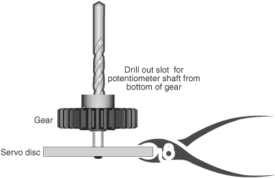
Figure 23-9 If modifying a servo where the slot for the potentiometer shaft is molded into the plastic of the output gear, attach the gear to a servo horn and drill out the bottom with a 3/16″ drill bit. Hold the servo horn with pliers.
LIMITATIONS OF MODIFIED SERVOS
Modifying a servo for continual rotation carries with it a few limitations, exceptions, and “gotchas” that you’ll want to keep in mind:
![]() The average servo is not engineered for lots and lots of continual use. The mechanics of the servo are likely to wear out after perhaps as little as 25 hours (that’s total elapsed time, which for a robot is quite a long time), depending on the amount of load on the servos. Models with metal gears and/or brass bushing or ball bearings will last longer.
The average servo is not engineered for lots and lots of continual use. The mechanics of the servo are likely to wear out after perhaps as little as 25 hours (that’s total elapsed time, which for a robot is quite a long time), depending on the amount of load on the servos. Models with metal gears and/or brass bushing or ball bearings will last longer.
![]() Standard-size servos are not particularly strong in comparison to many other DC motors with gearboxes. Don’t expect a standard servo to move a 5- or 10-pound robot. If your robot is heavy, consider using either larger, higher-output servos (such as 1/4-scale or sail winch) or, better yet, DC motors with bolted-on gearboxes.
Standard-size servos are not particularly strong in comparison to many other DC motors with gearboxes. Don’t expect a standard servo to move a 5- or 10-pound robot. If your robot is heavy, consider using either larger, higher-output servos (such as 1/4-scale or sail winch) or, better yet, DC motors with bolted-on gearboxes.
![]() Last and certainly not least, remember that modifying a servo voids its warranty.
Last and certainly not least, remember that modifying a servo voids its warranty.
Using Servo Motors for Sensor Turrets
After all this talk of using R/C servos as robot drive motors it’s easy to forget what they were created for in the first place: for precise position and control. A common application in robotics is the sensor turret, so called because it acts as a rotating turret (like a cannon gun turret) for one or more robot sensors. Typical sensors for turrets include ultrasonic and infrared proximity detection—these are detailed in Chapter 43, “Proximity and Distance Sensing.”
The concept of the rotating sensor turret is simple: put a sensor on top of the servo, and then “scan” it back and forth by alternating the position of the servo left and right. A simple way to mount a sensor is atop a servo horn. You can use double-sided foam tape, hot-melt glue, even a rubber band (wound around a couple of times) to secure the sensor to the horn.
Or use a specialty sensor bracket, like the one in Figure 23-10. Sensor brackets come in all shapes and sizes; the one in the picture is designed for the typical two-transducer ultrasonic sensor, such as the Devantech SRF05 or the Parallax Ping. Holes in the back of the bracket allow the connection wires to come through.
You can mount the servo to the robot using a variety of methods. Foam tape and glue are always options, but I prefer mechanical fasteners that can be easily removed and reattached; the fasteners make it easier to build and change the robot.
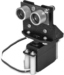
Figure 23-10 A servo used to rotate a sensor, mounted on a bracket.