
Chapter 45
Navigating Your Robot
Robots suddenly become useful once they can master their surroundings. Being able to wend their way through their surroundings is the first step toward that mastery.
The projects and discussion in this chapter focus on navigating your robot through space—not the outer-space kind, but the space between two chairs in your living room, between your bedroom and the hall bathroom, or outside your home by the pool.
The techniques used to provide such navigation are varied: line followers, wall followers, compass bearings, odometry, and more.
![]()
Source code for all software examples may be found at the RBB Online Support site. See Appendix A, “RBB Online Support,” for more details. To save page space, the lengthier programs are not printed here. The support site also offers source code with added comments, parts lists (with sources) for projects, updates, extended construction plans, and more examples you can try!
Tracing a Predefined Path: Line Following
Perhaps the simplest navigation system for mobile robots involves following some predefined path that’s marked on the ground. The path can be a black or white line painted on a hard-surfaced floor, a wire buried beneath a carpet, a physical track, or any of several other methods. This type of robot navigation is used in some factories. The reflective tape method is preferred because the track can easily be changed without ripping up the floor.
You can readily incorporate a tape-track navigation system into your robot. The line-following feature can be the robot’s only means of semi-intelligent action, or it can be just one part of a more sophisticated machine. You could, for example, use the tape to help guide a robot back to its battery charger nest.
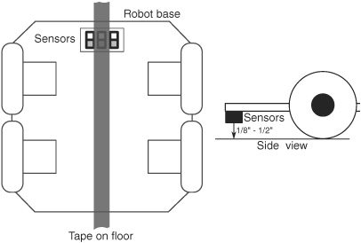
Figure 45-1 Placement of line-following sensors on the bottom of the robot. For best results, the sensors should be no more than 1/8″ to 1/2″ from the surface of the floor.
SETTING UP FOR FOLLOWING A LINE
With a line-following robot, you place a piece of white, black, or reflective tape on the floor—the color of the tape selected to contrast with the floor.
For the best results, the floor should be hard, like wood or linoleum, and not carpeted. One or more optical sensors are placed under the robot. These sensors incorporate an infrared LED and an infrared phototransistor. When the transistor turns on, it sees the light from the LED reflected off the tape. Obviously, the darker the floor, the better, because the tape shows up against the background.
You can build your own line following sensors, or use a commercially available LED-phototransistor pair. Mount the detectors on the bottom of the robot, as shown in Figure 45-1, in which detectors have been strategically placed so they straddle the width of the tape.
Figure 45-2 shows several variations, using 1/4″-, 1/2″-, and 3/4″-wide art tape. You might try the spacings as shown, but feel free to experiment with other variations. Figure 45-3 shows the basic sensor circuit and how the LED and phototransistor are wired. Most line-following robots use three pairs of these LED/phototransistors to straddle the track:
![]() The pairs on either side tell the robot it’s veered off too far left or right. To counter the mistracking, the robot steers in the opposite direction of the sensor pair that was activated. For example, if the right sensor pair sees the line, the robot corrects by steering to the left.
The pairs on either side tell the robot it’s veered off too far left or right. To counter the mistracking, the robot steers in the opposite direction of the sensor pair that was activated. For example, if the right sensor pair sees the line, the robot corrects by steering to the left.
![]() The sensor pair in the center is used to indicate correct tracking. As long as this sensor sees the line, then the robot is headed in the correct direction.
The sensor pair in the center is used to indicate correct tracking. As long as this sensor sees the line, then the robot is headed in the correct direction.

Figure 45-2 There is some flexibility in the spacing of the sensors in relation to the width of the tape, but on most line-following bots the sensors are spaced at about the same width as the line being tracked.
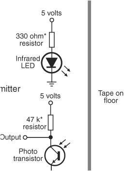
Figure 45-3 Circuit diagram for an LED emitter and phototransistor pair, used for line following (and other robotic tasks). The resistor above the infrared emitter should be selected to provide a high current to the LED, but without destroying it, of course. If the light from the emitter is too weak, the phototransistor may not pick it up. See Chapter 31 on how to calculate the value of the resistor used for limiting current through an LED.
Some robot builders prefer using a photoresistor (CdS cell) rather than a phototransistor. Photoresistors are often desired because their sensor sees a larger area, and they are naturally slower to react to changes in light intensity.

However, since photoresistors are most sensitive to the middle of the visible light spectrum (see Chapter 44 for more details), it’s best to use green or yellow LEDs for illumination, rather than infrared emitters. The output of photoresistors is also not as consistent as that of phototransistors. Even among components of the same brand and model, one cell may have a higher output value than another. This may require you to selectively adjust the sensitivity of the photoresistor by altering the value of its series resistor.
SELECTING PROPER RESISTOR VALUES
Specifications for infrared LEDs and phototransistors vary widely. You may need to play with the values for the two resistors shown in Figure 45-3 to determine what works best for the parts you have.
![]() The resistor above the infrared emitter LED controls the brightness of the LED.
The resistor above the infrared emitter LED controls the brightness of the LED.
![]() The resistor above the phototransistor controls the sensitivity of the phototransistor.
The resistor above the phototransistor controls the sensitivity of the phototransistor.
Both work hand-in-hand to provide the proper amount of light and detection.
Some LEDs don’t emit as much light as others, so you may need to increase their current so that they glow more brightly. I’ve specified a 330 Ω resistor to start; decrease the value of the resistor (to no less than 200 Ω) to increase the output of the LED. Conversely, if the LED is too bright—it spills light everywhere and causes the phototransistor to falsely trigger—you’ll need to increase the value of the resistor to perhaps 470 Ω to 1 kΩ.
Similarly, I’ve specified a 47 kΩ resistor for the phototransistor. You can experiment with values as low as 3.3 kΩ and as high as 470 kΩ and higher. The lower the resistance, the less sensitive the phototransistor is to light. If you don’t seem to be getting much voltage swing when alternately hiding and exposing the phototransistor to a bright light source, try a higher value for this resistor. For my prototype tests, I used a RadioShack infrared transistor, #276-0148. The 47 kΩ resistor value provided good response, but the phototransistor continued to work even with much lower and much higher values.
EMITTER/SENSOR LAYOUT
Though many line-following robots use three sets of emitters/detectors as previously described, there are plenty of variations you might want to experiment with, as shown in Figure 45-4. The three-pair arrangement is simply a convenience because you can purchase emitter/detectors as a prepackaged set.
One emitting source and two detectors: A single LED (infrared or visible) is placed in the center, flanked by two photo-sensitive sensors (phototransistors in the case of an infrared source; photoresistors for a visible source). This has the benefit that both sensors receive the same intensity of light when over the same color. This saves you from having to calibrate the sensors or light sources to make them even.
Four (or more) emitting sources/detectors: There’s no rule that says you just have to use three pairs of emitters and detectors. With more sensor pairs you can write more elaborate software for controlling the robot. Sensor pairs in the middle can be used for modest course correction, while those toward the outside indicate serious mis-steering.
Not sure if your infrared LEDs are putting out any light? Try taking a picture of them using a camcorder or a cell-phone camera. These devices tend to be sensitive to infrared, so if the LEDs are working, you’ll see it in the picture as a white light.
USING READY-MADE EMITTER/DETECTOR PAIRS
You may opt for a ready-made solution whereby the IR LED and phototransistor are in a single module, perhaps mounted on a small circuit board that you can attach to your robot. Figure 45-5 shows an array of eight light emitter/detector pairs on a single board (two of the pairs can be snapped off, making for two or six pairs, if that’s more convenient).

Figure 45-4 Alternative arrangements for emitter/detector pairs used for line following. You can orient the pairs horizontally and vertically, share one emitter with several detectors, or use more than three emitter/detector pairs.
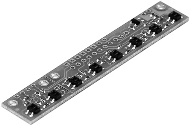
Figure 45-5 Infrared emitter/detector sensor array. Each pair is separated by 0.375″ (3/8″). Two of the pairs can be snapped off on their own. (Photo courtesy Pololu.)
AVOID OVERLY TIGHT TURNS
Your robot won’t be able to make the turn if it’s too tight. When drawing a line for your bot to follow, try more gradual turns rather than abrupt intersections. Otherwise, the robot might skip the line and go off course. The actual turn radius will depend entirely on the robot—its size, wheel base dimensions, and speed.
At the same time, you don’t want to shy away from the challenge of making your robot handle increasingly tight turns. Line following is a learned art; start out simple, and progress from there. With the right design and programming, your bot may be able to literally turn on a dime. It takes experience to get to that point in your robot-building prowess.
LINE-FOLLOWING SOFTWARE
Any microcontroller is up to the task of navigating a robot over a line. On a three-sensor line follower, three input lines are required. Your program monitors the status of the three sensors and adjusts the motors accordingly.
Figure 45-6 shows a wiring diagram for connecting a trio of infrared light emitters and detectors to an Arduino. Refer to the section “Selecting Proper Resistor Values,” previously in this chapter, for more information on experimenting with the values of the resistors used in the circuit. The program line_follow.pde controls the typical two-wheeled robot using these three sensors.
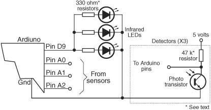
Figure 45-6 Arduino connection diagram for a three-pair emitter/detector line follower. The LEDs are driven through a digital output (so they can be turned on and off, or even pulsed). The output of each phototransistor is connected to a separate analog I/O pin of the Arduino.
In operation, when the sensor pair to the left sees the line, the left motor is very briefly stopped. This has the effect of veering the robot to the left. The reverse happens when the sensor pair to the right sees the line.
The “color” of the line is important, and ideally your line-following software should be selectable between black-on-white and white-on-black. This entails reversing the logic on the input pins: LOW is treated as HIGH, and vice versa.

line_follow.pde
To save space, the program code for this project is found on the RBB Online Support site. See Appendix A, “RBB Online Support.”
OTHER USES FOR LINE-FOLLOWING SENSORS
You can adapt line-following sensors for other robotic applications. For example, use the sensors to detect when the robot is about to go off the edge of a table or stairs. As long as the sensor(s) see light, the robot is over even ground. But when the reflected light is absent, it could indicate a steep falloff to the ground below.
Obviously, this technique works best for robots on which the line sensors are ahead of the drive wheels. It’s less helpful if the wheels are in the front with the sensors; the robot won’t know it’s falling over a cliff until it’s already heading down!
Wall Following
Robots that can follow walls are similar to those that can trace a line. Like the line, the wall is used to provide the robot with navigation orientation. One benefit of wall-following robots is that you can use them without having to paint any lines or lay down tape. Depending on the robot’s design, the machine can even maneuver around small obstacles.
VARIATIONS OF WALL FOLLOWING
Wall following can be accomplished with any of four methods. All are shown in Figure 45-7.
![]() Contact. The robot uses a mechanical switch, or a stiff wire that is connected to a switch, to sense contact with the wall. This is by far the simplest method, but the switch is prone to mechanical damage over time.
Contact. The robot uses a mechanical switch, or a stiff wire that is connected to a switch, to sense contact with the wall. This is by far the simplest method, but the switch is prone to mechanical damage over time.
![]() Noncontact, active sensor. The robot uses active proximity sensors, such as infrared or ultrasonic, to determine its distance from the wall. No physical contact with the wall is needed.
Noncontact, active sensor. The robot uses active proximity sensors, such as infrared or ultrasonic, to determine its distance from the wall. No physical contact with the wall is needed.
![]() Noncontact, passive sensor. The robot uses passive sensors, such as linear Hall effect switches, to judge distance from a specially prepared wall that is equipped with a wire carrying an alternating current. When the robot is in the proximity of the wire, the sensor will pick up the induced magnetic field provided by the alternating current.
Noncontact, passive sensor. The robot uses passive sensors, such as linear Hall effect switches, to judge distance from a specially prepared wall that is equipped with a wire carrying an alternating current. When the robot is in the proximity of the wire, the sensor will pick up the induced magnetic field provided by the alternating current.
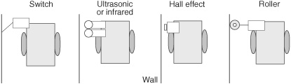
Figure 45-7 Several methods for wall following, including noncontact (ultrasonic, infrared, Hall effect) or contact (roller, whisker switch).
![]() “Soft-contact.” The robot uses mechanical means to detect contact with the wall, but the contact is “softened” by using pliable materials. For example, you can use a lightweight foam wheel as a “wall roller.
“Soft-contact.” The robot uses mechanical means to detect contact with the wall, but the contact is “softened” by using pliable materials. For example, you can use a lightweight foam wheel as a “wall roller.
In all cases, upon encountering a wall, the robot goes into a controlled program phase to follow the wall in order to get to its destination. In a simple contact system, the robot may back up a short moment after touching the wall, then swing in a long arc toward the wall again. This process is repeated, and the net effect is that the robot “follows the wall.”
With the other methods, the preferred approach is for the robot to maintain proper distance from the wall. Only when proximity to the wall is lost does the robot go into a “find wall” mode. This entails arcing the robot toward the anticipated direction of the wall. When contact is made, the robot alters course slightly and starts a new arc.
Odometry: Calculating Your Robot’s
Distance of Travel
Odometry is the technique of counting the revolution of a robot’s wheels to determine how far it’s gone. Odometry is perhaps the most common method to determine where a robot is at any given time (it also can provide other information, such as speed). It’s cheap and easy to implement, and it is fairly accurate over short distances.
Odometers are often referred to as encoders or shaft encoders because they are mounted on the shafts of motors and wheels to count revolutions. The terms “odometer,” “encoder,” and “shaft encoder” are often used interchangeably.
Encoders allow you to measure not only the distance of travel of a robot, but its velocity. By counting the number of transitions provided by the encoder, the robot’s control circuits can keep track of the revolutions of the drive wheels.
OPTICAL ENCODERS
Perhaps the most common method of adding odometry to robots is to attach a small disc (also called a codewheel) to the hub of a drive wheel. The disc works as part of an optical system, either reflective or transmissive. With either method, a pulse is generated each time the photodetector senses the light.
![]() With a reflective disc, infrared light strikes the disc and is reflected back to a photodetector. Both the infrared LED and the photodetector are mounted on the same side of the disc.
With a reflective disc, infrared light strikes the disc and is reflected back to a photodetector. Both the infrared LED and the photodetector are mounted on the same side of the disc.
![]() With a transmissive disc, infrared light is alternatively blocked and passed by slots or small cutouts. The light is detected by a sensor mounted on the opposite side of the LED.
With a transmissive disc, infrared light is alternatively blocked and passed by slots or small cutouts. The light is detected by a sensor mounted on the opposite side of the LED.
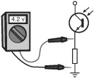
MAGNETIC ENCODERS
You can construct a magnetic encoder using a Hall effect switch (a semiconductor sensitive to magnetic fields) and one or more magnets. A pulse is generated each time a magnet passes by the Hall effect switch. A variation on the theme uses a metal gear and a special Hall effect sensor that is sensitive to the variations in the magnetic influence produced by the gear.

A bias magnet is placed behind the Hall effect sensor. A pulse is generated each time a tooth of the gear passes in front of the sensor. The technique provides more pulses on each revolution of the wheel or motor shaft, and without having to use separate magnets on the rim of the wheel or wheel shaft.
MECHANICAL ENCODERS
A low-cost form of encoder uses mechanical contacts rather than light or magnets. While technically encoders, these are used more as digital potentiometers; in fact, many mechanical encoders are made with a push-on/push-off switch feature for use as such things as power and volume controls on car radios. Many have a “detent,” tactile feedback when turning the dial.
While you can use a ready-made mechanical encoder with your robot, you’ll probably find it doesn’t last nearly as long as the other types. After a period of time spinning back and forth in your robot, the mechanical contacts of the encoder will simply give out.
A CLOSER LOOK AT ODOMETRY
Your robot uses odometry to judge distance of travel (and speed, if needed) by counting electrical pulses.
Let’s say the codewheel disc has 50 slots around its circumference. That represents a minimum sensing angle of 7.2°. As the wheel rotates, it provides a signal pulse to the counting circuit every 7.2°. By counting those pulses and calculating how many pulses there are each second, and knowing the diameter of the wheels on your robot, you can determine distance and speed.
Suppose the robot is outfitted with a 7″ wheel (circumference = 21.98″; you calculate circumference by multiplying the diameter of the wheel by pi, or approximately 3.14). Given a pulse every 7.2° of the wheel’s rotation, that produces a resolution that is approximately 0.44 linear inch per pulse. This figure was calculated by taking the circumference of the wheel and dividing it by the number of slots in the codewheel disc. If your robot counts 100 pulses, it knows it’s moved 0.44″ × 100, or 44″. If the robot uses the traditional two-wheel-drive approach, optical encoders are attached to both wheels. This is necessary because the drive wheels of a robot are bound to turn at slightly different speeds over time. By integrating the results of both optical encoders, it’s possible to determine where the robot really is, as opposed to where it should be. As well, if one wheel rolls over a cord or other small lump, its rotation will be hindered; this can cause the robot to veer off course.
ANATOMY OF A REFLECTIVE ENCODER
Perhaps the easiest type of odometer to build is the reflective encoder, like that in Figure 45-8. You can use the inside surface of a wheel to paste on a circular pattern of white/black stripes. This forms the encoder disc (codewheel) itself. You then mount an infrared emitter and detector close to the codewheel. As the wheel turns, the detector senses the light/dark pattern on the codewheel, providing a signal for use with your control electronics.
![]()
See the RBB Online Support site (see Appendix A) for a variety of free codewheel designs that you can download and print.
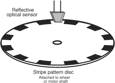
Figure 45-8 Single-stripe reflectance disc for wheel odometry. An emitter/detector pair is positioned over the stripe and senses the white/black pattern as the disc rotates.
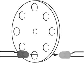
Figure 45-9 A transmissive disc uses a break-beam approach to sensing the stripe pattern. The disc may be optically opaque, with holes, or it may be a clear film, glass, or plastic, with solid black stripes coated over it.
When printing a pattern for a reflective codewheel, the paper should be thick (24# or more) gloss or semigloss. Photo-quality paper is a good choice to start. Be sure your printer has a relatively new ink or toner cartridge. Set the print quality to Extra Super Super High Fine (or whatever the highest setting is).
As an alternative, you can take your pattern to a professional copy center and have them make a print using a wax-based or other dense-medium toner/ink.
ANATOMY OF A TRANSMISSIVE ENCODER
A transmissive encoder is a disc that has numerous holes or slots near its outside edge. Rather than reflect light off a printed pattern, transmissive encoders pass light through the disc. An infrared emitter is placed on one side of the disc, so that its light shines through the holes or slots. An infrared-sensitive detector is positioned directly opposite (see Figure 45-9) so that when the disc turns, the holes pass the light intermittently. The result, as seen by the detector, is a series of flashing lights.
Transmissive encoders are harder to build because you need to cut or drill the holes/slots into a solid material. That material must be opaque to infrared light; many types of dark or black plastics actually let through infrared, making them unsuitable. A thin sheet of metal is the best overall choice, followed by an ABS or PVC plastic. Black-tinted polycarbonate or acrylic likely won’t do.
You may be able to find already machined parts that closely fit the bill, such as the encoder wheels in a discarded mouse (the computer kind, not the live rodent kind). The mouse contains two encoders, one for each wheel of the robot.
ENCODER RESOLUTION
With both reflective and transmissive odometers, the number of stripes/holes/slots in the disc determines the resolution of the encoders. This in turn affects the accuracy of the distance measurement. The more stripes, holes, or slots, the better the accuracy.
For reflective encoders, increasing the number of stripes is straightforward. Depending on the type and quality of your printer, and the size of the pattern, you can easily make discs with 100+ stripes.
MEASURING DISTANCE
Odometry measurements can be made using a microcontroller that is outfitted with a pulse accumulator or counter input. These kinds of inputs independently count the number of pulses received since the last time they were reset. To take an odometry reading, you clear the accumulator or counter, then start the motors. Your software need not monitor the accumulator or counter. Stop the motors, then read the value in the accumulator or counter. Multiply the number of pulses by the known distance of travel for each pulse (this will vary depending on the construction of your robot: consider the diameter of the wheels and the number of pulses of the encoder per revolution).
If the number of pulses from both encoders is the same, you can assume the robot traveled in a straight line, and you have only to multiply the number of pulses by the distance per pulse.
Another method of odometry uses the timing between the pulses. In some ways this technique is easier and doesn’t require your robot’s controller to tally up the pulses it has received. Programming commands for timing pulses include pulseIn for the Arduino, and pulsin for the PICAXE. Downsides to this method:
![]() The pattern used in the codewheel should be exact. No hand-drawn art here. Use a commercially made codewheel, or print one out from a pattern, such as those on the RBB Online Support site.
The pattern used in the codewheel should be exact. No hand-drawn art here. Use a commercially made codewheel, or print one out from a pattern, such as those on the RBB Online Support site.
![]() Pulse timing commands have a minimum resolution and depend greatly on the operating speed of the microcontroller. A PICAXE running at 4 MHz has a minimum pulse measuring resolution of 10 μs, for example; at 16 MHz it’s 2.5 μs. For best results, use a code-wheel with no more than 6 to 16 stripes (or holes). This helps to maximize the duration of the pulses, because there aren’t as many transitions during one revolution of the wheel.
Pulse timing commands have a minimum resolution and depend greatly on the operating speed of the microcontroller. A PICAXE running at 4 MHz has a minimum pulse measuring resolution of 10 μs, for example; at 16 MHz it’s 2.5 μs. For best results, use a code-wheel with no more than 6 to 16 stripes (or holes). This helps to maximize the duration of the pulses, because there aren’t as many transitions during one revolution of the wheel.
MOUNTING THE CODEWHEEL AND OPTICS
With the codewheels made, you need to mount them to the wheel (or motor shaft) and secure the infrared emitter/detector optics.
Mounting the Codewheel Discs
![]() For reflective encoders, cut out the disc and paste it to the inside of the wheel. If the wheel isn’t smooth enough, find or make a thin plastic disc that can act as a backstop. Unless the paper for the disc is absolutely opaque, best use a white-colored backstop.
For reflective encoders, cut out the disc and paste it to the inside of the wheel. If the wheel isn’t smooth enough, find or make a thin plastic disc that can act as a backstop. Unless the paper for the disc is absolutely opaque, best use a white-colored backstop.
![]() For transmissive encoders, mount the disc 1/4″ or more away from the inside of the wheel. Use a spacer at the hub of the wheel to maintain separation.
For transmissive encoders, mount the disc 1/4″ or more away from the inside of the wheel. Use a spacer at the hub of the wheel to maintain separation.
Mounting the Sensor Optics
Using brackets, attach the infrared emitter and detector so they fit snugly near the codewheel. For reflective encoders, you’ll want to place the sensor within about 1/8″ to no more than 1/4″ away from the disc. For transmissive encoders, be sure to orient the emitter and detector so that they face each other directly. You can bend the lead of the emitter and/or detector a bit to line it up with the holes.
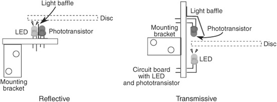
Figure 45-10 Mounting for both reflective and transmissive codewheels. For both, you may wish to use light baffles or tubes to prevent stray light from striking the detector.
For either encoder type, you’ll want to mask the phototransistor detector with a light baffle (thick piece of black felt or something similar) so it doesn’t pick up stray light or reflected light from the emitter. See Figure 45-10 for details. If the phototransistor you’re using doesn’t have a built-in infrared filter (and it should), you can increase the effectiveness of the sensor by adding an infrared filter over it.
ELECTRICAL INTERFACE AND CONDITIONING
Figure 45-11 shows the hookup diagram for the emitter and detector of an optical encoder. The same circuit works for both reflective and transmissive, and from now on, for simplicity, I’ll assume you’re using the reflective type.
The outputs of the phototransistors might need to be conditioned before they can be connected to a microcontroller. Otherwise, you could get all kinds of false signals and inaccurate readings. The circuit uses a Schmitt trigger, a kind of buffer circuit that smoothes out the wave shape of the light pulses. The output of the buffer is limited to only on and off. This helps prevent spurious triggers and provides a cleaner output.
The output of the Schmitt trigger is applied to the control circuitry of the robot. You can use either an inverting or a noninverting Schmitt trigger, as the circuit is interested only in on and off transitions.
The exact values of the resistors to use depend on the specifications of the infrared LED and phototransistor you use in your encoder. Try the values shown, and adjust as needed.
![]() The resistor above the LED controls the brightness of the LED: use a lower value to make the LED brighter; a higher value if the LED is too bright, and the phototransistor always sees light. Be sure not to choose too low of a value for the resistor (anything below about 200 Ω) or the LED could be damaged from too much current.
The resistor above the LED controls the brightness of the LED: use a lower value to make the LED brighter; a higher value if the LED is too bright, and the phototransistor always sees light. Be sure not to choose too low of a value for the resistor (anything below about 200 Ω) or the LED could be damaged from too much current.

Figure 45-11 Electrical connection of infrared LED emitter and phototransistor used for wheel odometry, including a Schmitt trigger interface.
![]() The resistor above the phototransistor determines the sensitivity of the phototransistor. A lower value makes the transistor less sensitive; a higher value, the inverse.
The resistor above the phototransistor determines the sensitivity of the phototransistor. A lower value makes the transistor less sensitive; a higher value, the inverse.
Note that the Schmitt trigger inverts the signal: as the output of the phototransistor increases, the Schmitt trigger changes from HIGH to LOW. If you’d rather it work the other way, flip the order of the transistor and its resistor (the resistor goes on the bottom). Or route the output of the trigger to another trigger—that inverts the inversion.
TESTING YOUR ENCODERS
To test your encoder, connect the phototransistor to a multimeter. Slowly rotate the wheel or motor shaft. If the system is working properly, you should see a definite voltage swing as the detector goes past the light and dark stripes. If you don’t see much difference, double-check your work, and be sure the detector isn’t being spoiled by room light (turn the work lamp on your desk away from the wheel).
![]() If the voltage stays the same and is too high, the emitter may be overdriven. Try a higher value for the resistor above the emitter LED. This reduces the output of the emitter.
If the voltage stays the same and is too high, the emitter may be overdriven. Try a higher value for the resistor above the emitter LED. This reduces the output of the emitter.
![]() If the voltage stays the same and is too low, the emitter may be underdriven. Try a lower value for the resistor above the emitter LED—but never go below about 200 Ω, or the emitter may be damaged.
If the voltage stays the same and is too low, the emitter may be underdriven. Try a lower value for the resistor above the emitter LED—but never go below about 200 Ω, or the emitter may be damaged.
![]() If the voltage changes only slightly, then the stripe pattern may not be dark enough. The black stripes might be reflecting too much infrared light. Reprint the discs, being sure to use fresh toner or ink cartridges. If available, set the printing options to a darker level.
If the voltage changes only slightly, then the stripe pattern may not be dark enough. The black stripes might be reflecting too much infrared light. Reprint the discs, being sure to use fresh toner or ink cartridges. If available, set the printing options to a darker level.
Not sure if the infrared emitters are emitting infrared? A quick check is to point a digital camera or camcorder at them. You should see a white glow from the emitter. Though invisible to the human eye, digital imaging sensors are sensitive to the light from infrared emitters.
PROGRAM FOR COUNTING PULSES
Your wheel encoders are now ready to rumble and need only be connected to a microcontroller or other circuit. The program listing in single_encoder.pde shows how to implement a basic pulse-counting odometer using an Arduino microcontroller.
single_encoder.pde
To save space, the program code for this project is found on the RBB Online Support site. See Appendix A, “RBB Online Support,” for more details.
USING QUADRATURE ENCODING
So far, we’ve investigated encoders that have just one output. This output pulses as the code-wheel spins. By using two emitters and two detectors, positioned 90° out of phase from one another (see Figure 45-12), you can construct a system that tells you not only the amount of travel, but the direction as well.
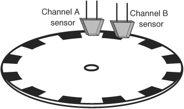
Figure 45-12 Single-stripe reflectance codewheel discussed for quadrature encoding. The emitter/detector pairs are placed so that one is 90° out of phase with the other.
Being able to determine the direction of travel is useful if the wheels of your robot slip. You can determine if the wheels are moving when they aren’t supposed to be, and you can determine the direction of travel. This so-called two-channel system uses quadrature encoding—the channels are out of phase by 90° (one-quarter of a circle).
Rather than just counting on/off transitions, quadrature encoding counts all the variations between the two sensors:
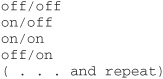
It might not be immediately obvious, but because quadrature encoders trigger on four events instead of just one, the effective resolution of the odometers is increased by four. That is, if the disc has 10 stripes, rather than a resolution of 10 transitions per revolution, you get 40.
Figure 45-13 shows the on/off waveform of a quad encoder. The two sets of stripes on the disc define the channels of the encoder, referred to as Channel A and Channel B. Note that in one direction, Channel A “leads” Channel B; when the disc spins in the other direction, Channel B leads Channel A. This is how direction can be determined in a quad encoder setup.
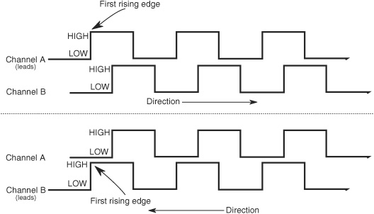
Figure 45-13 How the timing relationship between the Channel A and Channel B pulses indicates the direction of rotation in a quadrature encoder.
The “secret” behind quadrature encoding is that the two channels are set apart by 90°. Starting at the top of the disc, there is a white stripe, followed by a black stripe; think of these two segments as a whole circle. The stripes on the inside are 90° out of phase with the stripes or the outside.
Another depiction of quadrature timing and the “phases” that are created is Figure 45-14—here, the stripes are laid out horizontally to aid in understanding the sequence. The signals from the two channels rise and fall between the white and black stripes.
![]()
If you’re using quadrature encoding, you’re best off using a specialty integrated circuit for signal conditioning. These circuits are specially made to condition, equalize, and process the pulses from encoders that use two sensors instead of just one. See the RBB Online Support site (see Appendix A) for a free bonus project that uses an affordable and easily attainable IC specially designed for quadrature encoding.
USING READY-MADE ENCODERS
You’re not limited to using just homebrew encoders. Commercially made optical, magnetic, and mechanical encoders are available, some of them are affordable, and a few of them are readily adaptable to robotics.
Perhaps the premier solution to quadrature encoding for robotics is the Wheel Watcher (see Figure 45-15), developed by Pete Skeggs at Nubotics. The product is sold through Acro-name and many other online specialty robotics retailers. The Wheel Watcher consists of a circuit board with all optics and signal-conditioning circuitry already added, plus a professionally printed striped codewheel.
Versions are available for use with standard R/C servo motors, as well as popular DC gear motors such as the GM2 and GM3 imported by Solarbotics. The codewheel is designed to fit several popular 2.5″-diameter injected molded wheels, and a spacer kit is available to secure the disc to most any other wheel that is attached to an R/C servo with a standard servo mounting horn.
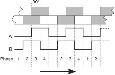
Figure 45-14 In quadrature encoding, the signals go through four phases, noted by the four possible values of the two channels: 0/0, 0/1, 1/1, and 1/0.
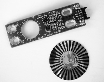
Figure 45-15 The Wheel Watcher module and accompanying reflective codewheel, made of black ink printed onto metalized plastic foil. The module provides an all-in-one quadrature encoding solution.
Other low-cost commercial odometers include kits from US Digital (www.usdigital.com) that work with motor shafts from 1.5mm to 4mm (059″ to 0.157″). These cost a bit more than other solutions, but they are still relatively inexpensive, considering their high quality and high accuracy. Several online robotics stores, including Lynxmotion and Pololu, offer similar products.
US Digital also sells transmissive optical discs of various diameters, reflective encoder modules with all the optics built in and properly spaced, and many other solutions. Perfect for any intermediate or advanced robotics project.
UNDERSTANDING ERRORS IN ODOMETRY
Odometers aren’t perfect. Over a 30- to 50-foot range it’s not uncommon for the average odometer to misrepresent the position of the robot by as much as half a foot or more!
Why the discrepancy? First and foremost: Wheels slip. As a wheel turns, it is bound to slip, especially if the surface is hard and smooth, or when there’s an obstacle on the floor. Second, certain robot drive designs are more prone to error than others. Robots with tracks are steered using slip, odometry is basically useless on most any tracked vehicle design.
And there are less subtle reasons for odometry error. If you’re even a hundredth of an inch off when measuring the diameter of the wheel, the error will be compounded over long distances.
You’re best off relying on odometry for short distances only. Assume that if your robot has made a turn, the actual distance traveled may be a bit different from what’s being reported.
WHEN YOU DON’T NEED ODOMETRY
Keep in mind that some robotics applications simply don’t need odometry, saving you the trouble of incorporating it into your designs. A good example is line-following robots. These are navigated using a predefined line, so their route is known.
Other examples include wall-following bots, though in some cases these can be augmented by simple distance measuring. And for obvious reasons, robots that walk on legs, swim over water, or fly in the air aren’t suitable for the type of odometry covered here.
Compass Bearings
Besides the stars, the magnetic compass has served as humankind’s principal navigation aid over long distances. You know how it works: a needle points to the magnetic north pole of the earth. Once you know which way is north, you can more easily reorient yourself in your travels.
Robots can use compasses as well, and a number of electronic and electromechanical compasses are available for use in hobby robots. One of the least expensive is the Dinsmore 1490, from Dinsmore Sensors. The 1490 looks like an overfed transistor, with 12 leads protruding from its underside. The leads are in four groups of three; each group represents a major compass heading: north, south, east, and west. The three leads in each group are for power, ground, and signal. A Dinsmore 1490 compass is shown in Figure 45-16.
The 1490 provides eight directions of heading information (N, S, E, W, SE, SW, NE, NW) by measuring the earth’s magnetic field. It does this by using miniature Hall effect sensors and a rotating compass needle (similar to ordinary compasses). The sensor is said to be internally designed to respond to directional changes much like a liquid-filled compass. It turns to the indicated direction from a 90° displacement in approximately 2.5 seconds. The manufacturer’s specification sheet claims that the unit can operate with up to 12° of tilt with acceptable error, but it is important to note that any tilting from center will cause a corresponding loss in accuracy.
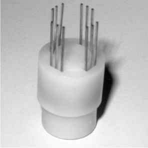
Figure 45-16 Dinsmore 1490 electromechanical compass. It has four outputs and can provide eight different compass bearings: N, E, S, W, and the in-between headings.
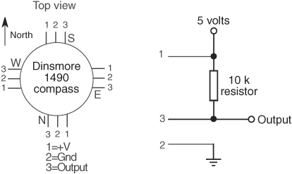
Figure 45-17 Connection diagram for the Dinsmore 1490 compass. Each set of three pins is connected in the same manner.
Figure 45-17 shows the circuit diagram for the 1490, which uses four inputs to a computer or microcontroller. Note the use of pull-up resistors. With this setup, your robot can determine its orientation with an accuracy of about 45° (less if the 1490 compass is tilted). Dinsmore also makes an analog-output compass that exhibits better accuracy.
![]()
Reversing the polarity of the leads of this device will damage it. Be sure to double-check your work before applying power. Figure 45-17 shows the pinout of the 1490 from the top, same as the datasheet provided by the manufacturer.
Electronic compasses with digital or analog outputs are now fairly common. A popular model is the Devantech CMPS09 compass, which is equipped with a three-axis magnetometer, a three-axis accelerometer, and its own microcontroller. The output of the sensor provides a compass bearing, as well as pitch and roll information (useful if robot is not level).
The sensor connects to your microcontroller using I2C or serial communications, or via PWM, where the width of pulses indicates bearing, from 0° to 360°, in 0.1° increments. The sketch in compass.pde shows the CMPS09 interfaced to an Arduino using IC2. The connection diagram is shown in Figure 45-18. Be very careful not to flip the 5V and Gnd connections. Note the 1.8 kΩ pull-up resistors: these are shown in the manufacturer’s example demos, but not everyone agrees on the “perfect” value for pull-up resistors used with I2C devices. If 1.8 kΩ resistors give you problems (and they shouldn’t unless your wiring is really careless), try slightly higher values, up to 4.7 kΩ.
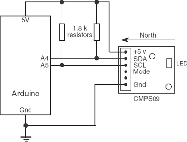
Figure 45-18 Connecting a Devantech CMPS09 compass to an Arduino. The CMPS09 uses I2C serial communications to provide reliable heading information.
compass.pde
To save space, the program code for this project is found on the RBB Online Support site. See Appendix A, “RBB Online Support,” for more details.
Compasses require careful placement on the robot to be useful. Because they sense magnetic fields, the compass must not be located near any large metal mass or near the strong magnetic fields of DC motors.
The compass.pde sketch also demonstrates retrieving pitch and roll information from the three-axis accelerometer that’s built into the CMPS09 compass. The built-in accelerometer is used to compensate for the tilt of the sensor, as a crooked compass will distort the reading of the compass. But you can also query the CMPS09 to display pitch (forward and back) and roll (side-to-side) position.
Experimenting with Tilt and Gravity Sensors
As every schoolchild learns, the human body has five senses: sight, hearing, touch, smell, and taste. These are primary developed senses; yet the body is endowed with far more senses that are often taken for granted. These more “primitive” human senses are typically termed “sixth senses”—a generic phrase for senses that don’t otherwise fit within the common five.
One of the most important “sixth senses” is the sense of balance. This sense is made possible by a complex network of nerves throughout the body, including those in the inner ear. The sense of balance helps us to stand upright and to sense when we’re falling.
Our sense of balance combines information about both the body’s angle and its motion. At least part of the sense of balance is derived from a sensation of gravity—the pull on our bodies from the earth’s mass.
Similarly, robots can be made to “feel” gravity. The same forces of gravity that help us to stay upright might provide a two-legged robot with the same ability. Or a rolling robot—on wheels or tracks—might avoid tipping over and damaging something by determining if its angle is too steep.
SENSORS TO MEASURE TILT
One of the most common means for providing a robot with a sense of balance is to use a tilt sensor or tilt switch. The sensor or switch measures the relative angle of the robot with respect to the center of the earth. Here are some of the more common methods:
![]() A mercury-filled glass ampoule that forms a simple on/off switch. The liquid mercury makes or breaks a connection to electrical contacts depending on the angle of the ampoule. The major disadvantage of mercury tilt switches is the mercury itself, which is a highly toxic metal.
A mercury-filled glass ampoule that forms a simple on/off switch. The liquid mercury makes or breaks a connection to electrical contacts depending on the angle of the ampoule. The major disadvantage of mercury tilt switches is the mercury itself, which is a highly toxic metal.
![]() The ball-in-cage is an all-mechanical switch popular in old pinball machines. The switch is a square or round capsule with a metal ball inside. The weight of the ball makes it touch the electrical contacts that are inside the capsule. The capsule may have multiple contacts so it can measure tilt in all directions.
The ball-in-cage is an all-mechanical switch popular in old pinball machines. The switch is a square or round capsule with a metal ball inside. The weight of the ball makes it touch the electrical contacts that are inside the capsule. The capsule may have multiple contacts so it can measure tilt in all directions.
![]() The ball-in-optical sensor is a variation on the ball-in-cage. These use an infrared emitter and an infrared detector in a housing. Put a small ball inside between the emitter and detector, and as the device tilts, the ball either blocks or allows light to pass.
The ball-in-optical sensor is a variation on the ball-in-cage. These use an infrared emitter and an infrared detector in a housing. Put a small ball inside between the emitter and detector, and as the device tilts, the ball either blocks or allows light to pass.
![]() An electronic spirit-level sensor uses the common fluid bubble you see on ordinary levels at the hardware store plus some interfacing electronics. It’s basically a glass tube filled with fluid. A bubble forms at the top of the tube, since it isn’t completely filled. When you tilt the tube, gravity makes the bubble slosh back and forth, and the position of the bumble indicates the angle.
An electronic spirit-level sensor uses the common fluid bubble you see on ordinary levels at the hardware store plus some interfacing electronics. It’s basically a glass tube filled with fluid. A bubble forms at the top of the tube, since it isn’t completely filled. When you tilt the tube, gravity makes the bubble slosh back and forth, and the position of the bumble indicates the angle.
![]() An electrolytic tilt sensor is like a mercury switch but is more complex and a lot more costly. A glass ampoule is filled with a special electrolyte liquid—that is, a liquid that conducts electricity but in very measured amounts. As the switch tilts, the electrolyte in the ampoule sloshes around, changing the conductivity between metal contacts.
An electrolytic tilt sensor is like a mercury switch but is more complex and a lot more costly. A glass ampoule is filled with a special electrolyte liquid—that is, a liquid that conducts electricity but in very measured amounts. As the switch tilts, the electrolyte in the ampoule sloshes around, changing the conductivity between metal contacts.
ENTER THE ACCELEROMETER
One of the most accurate, yet surprisingly low-cost, methods for tilt measurement involves an accelerometer. Once the province only of high-tech aviation and automotive testing labs, accelerometers are quickly becoming common staples in consumer electronics.
New techniques for manufacturing accelerometers have made them more sensitive and accurate yet less expensive. A device that might have cost upward of $500 a few years ago sells in quantity to manufacturers for under $5 today. Fortunately, the same devices used in cars and other products are available to hobby robot builders, though the cost is a little higher because we’re not buying 10,000 at a time!
The basic accelerometer is a device that measures change in speed. Many types of accelerometers are also sensitive to the constant pull of the earth’s gravity. It is this latter capability that is of interest to us, since it means you can use the accelerometer to measure the tilt, or “attitude,” of your robot at any given time. This tilt is represented by a change in the gravitational forces acting on the sensor.
SINGLE-, DUAL-, AND THREE-AXIS SENSING
The basic accelerometer is single axis, meaning it can detect a change in acceleration (or gravity) in one axis only. While this is moderately restrictive, you can still use such a device to create a capable and accurate tilt-and-motion sensor for your robot.
A dual-axis accelerometer detects changes in acceleration and gravity in both the X and Y planes. If the sensor is mounted vertically—so that the Y axis points straight up and down—the Y axis detects up-and-down changes, and the X axis will detect side-to-side motion. Conversely, if the sensor is mounted horizontally, the Y axis detects motion forward and backward, and the X axis detects motion from side to side.

A three-axis accelerometer detects changes in acceleration and gravity in all three planes, basically in 3D. These types of accelerometers are frequently used, along with gyro sensors, in certain kinds of self-balancing robots.
EXPERIMENTING WITH AN ACCELEROMETER
Of accelerometers for hobby use, the dual- or two-axis variety is probably the most common, with the ADXL family of components from Analog Devices among the most popular. The ADXL parts come as surface-mount components and require a few external components. Most folks get an ADXL-based accelerometer already mounted on a convenient breakout or experimenter’s board, like the one in Figure 45-19. The price is not that much more than just the bare chip, and it’s a whole lot more convenient. Just about all of the online robotics specialty outlets carry at least one dual-axis accelerometer, and most offer various models of the ADXL.
The ADXL accelerators include two- and three-axis versions, as well as components sensitive to different levels of gravity (or g) forces. For example, the ADXL320 is a dual-axis model, sensitive to +/−5g. Generally, a 2g to 10g accelerometer will provide a good balance between precision and performance limits. Most robotics applications don’t need to read gravity forces in excess of 5g.
The higher the g’s, the higher the force, impact, and acceleration you can measure, but the less sensitive the component to small changes. A model rocket could use an 18g or 50g accelerometer, but most robots not destined for space can make do with a lot less.
One other variation in accelerometers is the output signal. The three most common are analog, serial, and PWM.

Figure 45-19 A three-axis accelerometer breakout board, ready to be used in a robotics project. This particular model is adjustable between ±1.5g and ±6g, and provides an analog voltage proportional to the g-forces on the device. (Photo courtesy Pololu.)
![]() Analog output is a varying voltage, usually something a bit less than the full operating voltage of the accelerometer. Since accelerometers register both positive g-forces and negative g-forces, the output voltage at 0g is halfway between 0 and the operating voltage of the device.
Analog output is a varying voltage, usually something a bit less than the full operating voltage of the accelerometer. Since accelerometers register both positive g-forces and negative g-forces, the output voltage at 0g is halfway between 0 and the operating voltage of the device.
![]() Serial output uses I2C, SPI, or other serial communications to relay the g-force readings to the microcontroller or computer. While a bit more difficult to use than analog output, the serial data is less prone to noise and glitches, and on some accelerometers you can send it commands on the serial link to alter its behavior.
Serial output uses I2C, SPI, or other serial communications to relay the g-force readings to the microcontroller or computer. While a bit more difficult to use than analog output, the serial data is less prone to noise and glitches, and on some accelerometers you can send it commands on the serial link to alter its behavior.
![]() PWM output is a series of pulses whose duration changes depending on the g-forces on the accelerometer. To read the duration of the pulses, you need a microcontroller with an input capture (or similar) pin.
PWM output is a series of pulses whose duration changes depending on the g-forces on the accelerometer. To read the duration of the pulses, you need a microcontroller with an input capture (or similar) pin.
Figure 45-20 shows a typical connection of an ADXL-based analog output breakout board (in this case, that from SparkFun Electronics) to an Arduino microcontroller. (Note that the accelerometer in the figure is a self-contained module or breakout board. It’s not just the chip itself.)
The breakout boards have X, Y, and Z outputs, though not all devices provide the third axis. The program accel2.pde demonstrates how incredibly easy it is to set up and read the X- and Y-axis values of a dual-axis analog output accelerometer. The values appear in the Serial Monitor window.
The circuit shows attaching power to the 5V pin of the Arduino. This assumes you are using an accelerometer meant for 5 volts. If you’re using a 3.3-volt part, be sure to connect its power to the 3.3V pin of the Arduino.
![]()
Note also that 3.3-volt accelerometers that use PWM or serial output may not be able to directly connect to a microcontroller powered by 5 volts. You may need to use level-shifting logic to go from 3.3V to 5V. Consult the data sheet that comes with your accelerometer. The RBB Online Support site (see Appendix A) also provides hints and tricks regarding voltage level shifting.

Figure 45-20 Arduino hookup diagram for an ADXL3xx accelerometer breakout module (one that already has the necessary external components on it). The illustration shows a dual-axis model; for the Z axis, simply add another line to an unused analog input.
accel2.pde
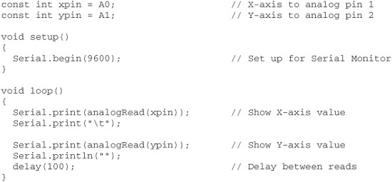
The values shown in the Serial Monitor window represent voltage from 0 (0 volts) to 1023 (5 volts). At 0g (the axis arrow sideways; that is, pointing neither up nor down), the output of the axis is 512. This is midway between 0 and 5 volts. At +1g (the axis arrow pointing up), the output rises to approximately 650. And at− 1g (axis arrow pointing down), the output lowers to 345.
These values were taken using an ADXL322, which has a +/−2g response. The exact values you get will be different, depending on the specific model of accelerometer you use. You’ll also encounter moderate variations in output levels—even between the X and Y outputs—due to the tolerance of the components. On my prototype, the +1g value was a full 10 points off between the X and Y outputs. This is to be expected, and you can adjust for it in your software.
Given these sample values, one real-world example is knowing when your robot has tipped over on its side, or is about to. Let’s assume the X axis of the accelerometer represents side-to-side tilt (you can mount your accelerometer in a number of ways, so you can choose what axis does what). With the accelerometer flat, the X axis will read 0g, or about 512. Any value above or below that reading indicates at least some tilt in the X axis. You might determine excessive tilt if the value is more than 75 points above or below 512.
ADDITIONAL USES FOR ACCELEROMETERS
Before we go into the details of using an accelerometer for angle or motion measurement, let’s review the different robotics-based applications for these devices. Apart from sensing the angle of tilt, a gravity-sensitive accelerometer can also be used for the following tasks:
![]() Shock and vibration. If the robot bumps into something, the output of the accelerometer will “spike” instantaneously. Because the output of the accelerometer is proportional to the power of the impact, the harder the robot bumps into something, the larger the voltage spike. You can use this feature for collision detection, obviously, but in ways that far exceed what is possible with simple bumper switches, since an accelerometer is sensitive to shock from most any direction.
Shock and vibration. If the robot bumps into something, the output of the accelerometer will “spike” instantaneously. Because the output of the accelerometer is proportional to the power of the impact, the harder the robot bumps into something, the larger the voltage spike. You can use this feature for collision detection, obviously, but in ways that far exceed what is possible with simple bumper switches, since an accelerometer is sensitive to shock from most any direction.
![]() Motion detection. An accelerometer can detect motion even if the robot’s wheels aren’t moving. This might be useful for robots that must travel over uneven or unpredictable terrain, or if the motors should stall because of an obstruction or obstacle. Should the robot move (or stop moving) when it’s not supposed to, this will show up as a change in speed and will therefore be sensed by the accelerometer.
Motion detection. An accelerometer can detect motion even if the robot’s wheels aren’t moving. This might be useful for robots that must travel over uneven or unpredictable terrain, or if the motors should stall because of an obstruction or obstacle. Should the robot move (or stop moving) when it’s not supposed to, this will show up as a change in speed and will therefore be sensed by the accelerometer.
![]() Telerobotic control. You can use accelerometers mounted on your clothes to transmit your movements to a robot. For instance, accelerometers attached to your feet can detect the motion of your legs. This information could be transmitted (via radio or infrared link) to a legged robot, which could replicate those moves. Or you might construct an “air stick” wireless joystick, which would simply be a pipe with an accelerometer at the top or bottom and some kind of transmitter circuit. As you move the joystick, your movements are sent to your robot, which acts in kind.
Telerobotic control. You can use accelerometers mounted on your clothes to transmit your movements to a robot. For instance, accelerometers attached to your feet can detect the motion of your legs. This information could be transmitted (via radio or infrared link) to a legged robot, which could replicate those moves. Or you might construct an “air stick” wireless joystick, which would simply be a pipe with an accelerometer at the top or bottom and some kind of transmitter circuit. As you move the joystick, your movements are sent to your robot, which acts in kind.
More Navigational Systems for Robots
For under $100 your robot can know exactly where on earth it’s located. Or precisely what room it’s in within your house (or even what wall or furniture it’s near). These techniques are described in a series of bonus articles you can find on the RBB Online Support site; see Appendix A. Included:
![]() Radio frequency identification, or RFID, uses small transponders that send signals to non-battery-powered tags you have mounted on nearby walls or objects. Each tag provides a unique code that identifies itself and, therefore, can be used as a kind of beacon system.
Radio frequency identification, or RFID, uses small transponders that send signals to non-battery-powered tags you have mounted on nearby walls or objects. Each tag provides a unique code that identifies itself and, therefore, can be used as a kind of beacon system.
![]() Global positioning satellite (GPS) is by now a well-known technique using satellites in space to provide location, altitude, even speed information. You can apply the same technology on your robot.
Global positioning satellite (GPS) is by now a well-known technique using satellites in space to provide location, altitude, even speed information. You can apply the same technology on your robot.
![]() Gyroscopes sense changes in speed and direction, and provide what’s known as inertial navigation. When coupled with other navigation techniques such as odometry and accelerometers, your robot can keep accurate track of where it is. Gyros (the instrument, not the food) are also used to construct self-balancing bots.
Gyroscopes sense changes in speed and direction, and provide what’s known as inertial navigation. When coupled with other navigation techniques such as odometry and accelerometers, your robot can keep accurate track of where it is. Gyros (the instrument, not the food) are also used to construct self-balancing bots.