
Chapter 12
Build a Motorized Metal Platform
Metal offers strength and ruggedness that wood and plastic cannot. While constructing robots out of metal requires more effort (and sharper tools for cutting and drilling), a properly made metallic bot will last years and years and is suitable for both indoor and outdoor use.
This chapter details the construction of a small but flexible TinBot, using metal for its principal body parts. Its design uses commonly found hardware, which keeps down its cost and limits the amount of hacking pieces of metal down to the size and shape you want. In fact, construction of the TinBot requires only two cuts through thin-gauge steel. The cuts are relatively easy to make using an ordinary hacksaw.

Before you build the TinBot, review Chapter 23 on how to use radio control (R/C) servo motors with your robots. This type of motor cannot be simply attached to a battery to make the bot operate.
R/C motors require a special control signal. In robotics the most common way of providing this control signal is with a microcontroller. These specialty electronic circuits are designed in-depth in Part 7 of this book.
Making the Base
Refer to Table 12-1 for a list of parts.
Figure 12-1 shows the completed TinBot, which measures 7″ × 6-1/4″, and stands about 2-1/4″ high. It’s powered by two radio-controlled servo motors. Ordinarily, these kinds of motors operate in a confined arc of about 90° to 180°. But the motors on the TinBot have been modified for continuous rotation, so they function like ordinary gear motors.
You can either modify the motors yourself, following instructions provided in Chapter 23, “Using Servo Motors,” or buy them already modified. You can find the already modified ones at many online specialty robotics Web sites, such as Parallax and Pololu. Cost is only slightly more than the typical standard servo motor, but they save you the hassles of modifying the servo yourself.
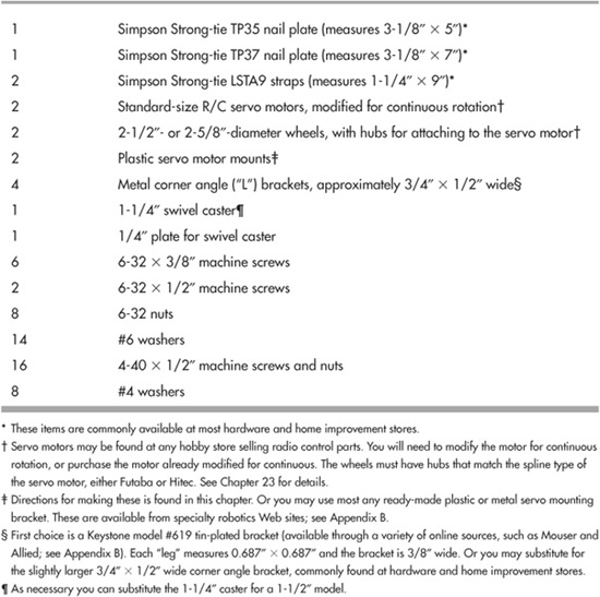
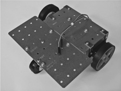
Figure 12-1 The completed TinBot, made with common metal plates found at the hardware or home improvement store.
TinBot’s metal body consists of 20-gauge galvanized steel nail plates (see Figure 12-2), intended for home construction and repair. The Simpson Strong-tie hardware I’ve listed is a common find at many home improvement stores, as well as online hardware retailers. If this exact brand is not available, you can substitute most anything else that matches the approximate dimensions.
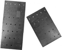
Figure 12-2 Simpson Strong-tie TP35 and TP37 steel nail plates used for the body of the robot. Note the holes already drilled into the plates.
PREPARING THE METAL PIECES
As noted, the only cutting you need to do is to strip off a portion from the two LSTA9 straps. Using a hacksaw outfitted with a metal-cutting blade, cut the straps to a length of 5-1/2″. Use a miter box (see Figure12-3) to ensure a straight cut. Plastic miter boxes are inexpensive and are very handy for all kinds of robot construction chores. The cuts don’t need to be perfect, but file down any rough edges that may remain. Figure 12-4 shows the straps before and after cutting.
With the file still in your hands, use it to round off the edges of the TP37 plate, to remove the sharp corners.
If you have a pair of metal shears, either hand or power operated, these will make the chore of cutting the straps even easier. For best results, first use a hacksaw to score a shallow cut in the metal, then cut with the shears. Apply a dab of oil on the cutting surfaces to prolong the life of the tool.
DRILLING HOLES
Though the nailing plates and straps have holes in them, they don’t always match up where we want them to. Using some holes already in the plates, matching holes are drilled into the straps, as shown in Figure 12-5. The TinBot design uses one of the strap holes to get things started; you need to drill two additional holes in each strap.

Figure 12-3 You need to cut off a few inches from the nail straps. Use a hacksaw (with a sharp blade for metalwork) and, for best results, a miter box.

Figure 12-4 Original and shortened nail strap pieces. After cutting, file off the metal for a smooth edge.
Use a new or recently sharpened 9/64″ bit to drill the holes. As covered in Chapter 11, start each hole using a center punch or a sharp nail to make a slight indentation in the metal. Apply a small drop of cutting oil, then set your drill motor to low. Allow the tool to do the work for you. Don’t press down too hard, or you’ll dull the bit.

Figure 12-5 New holes need to be drilled into the nail straps to conform to the holes already in the TP35 and TP37 plates. For each strap you need to drill two new holes.
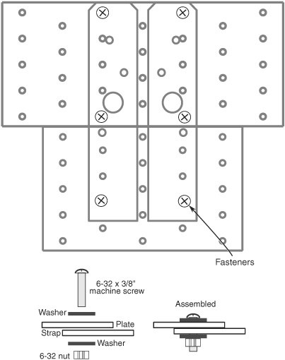
Figure 12-6 Use 6-32 fasteners to assemble the plates to the straps.
ASSEMBLING THE PLATES AND STRAPS
Assemble the metal plates and straps as shown in Figure 12-6. Use 6-32 hardware, with washers top and bottom. Finger-tighten only until all six fasteners have been assembled. Then go back and retighten everything.
MOUNTING THE SERVO MOTORS
Refer to Figure 12-7 for a layout diagram for the servo mounts. You need two of these. They may be constructed out of 1/4″ aircraft-grade plywood or expanded PVC, or 1/8″ polycarbonate or acrylic plastic (plywood and PVC are much easier to work with). The dotted lines along the bottom of the mount indicate optional “cut-throughs.” Cut through at the dotted lines if you have trouble cutting out the inside pocket for the servo. This creates a slightly weaker mount, but they’re easier to make.
You may also purchase ready-made servo plastic or metal mounts, though you may need to drill new holes to match the hole pattern in the nail plates. The hole spacings in the layout are designed to match the TP35 nail plate used on the TinBot.
The servo mounts are attached to the robot base using metal corner angle brackets, as shown in Figure 12-8. Assemble using 4-40 hardware. Be sure to tighten the screws securely, or they’ll work loose over time. The brackets should be about 3/4″ on each side of the angle.

Figure 12-7 Cutting and drilling guide for the servo motor mounts. The dotted lines along the bottom indicate optional cuts, for making it easier to create the inside “pocket” for the body of the servo motor.
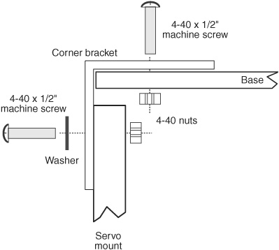
Figure 12-8 Assembly detail for attaching the servo motors to the TinBot. Use 3/4″ metal corner angle brackets and 4-40 fasteners.
Alternatively, you can do away with the servo mounts completely by attaching the servos directly to the corner angle brackets. This will require that you drill new holes in the TP35 plate to match the spacing of the mounting holes in the servo.
It also reduces the height of the robot by about 1/2″; this is not a problem per se, but it means the size of the caster must likewise be reduced to match. While there are 3/4″ and 1″ swivel casters available, they tend to be cheaply made and don’t turn well. You may want to swap the swivel caster for a ball caster, like the one used in the PlyBot in Chapter 8. These are more expensive, though.
MOUNTING THE CASTER
You also need to drill two holes for mounting the caster, which is used to balance the robot. The exact placement of the holes will depend on the exact caster you use. To mark the holes, place the baseplate of the caster against the metal, positioning it as shown in Figure 12-9. The caster is mounted right at the back edge of the TinBot.
Mount the caster using 6-32 hardware (see Figure 12-10). Note the spacer between the caster baseplate and the body of the robot. You can construct the spacer using a scrap piece of 1/4″ plywood or PVC plastic, or you can simply use a stack of three or four #6 washers. The spacer/washers increase the height of the 1-1/4″ caster to better match the drive motors and wheels. The added spacer is not needed if using a 1-1/2″ caster.
ATTACHING THE SERVO MOTORS AND WHEELS
As a final step, attach the servo motors into the servo mounts using 4-40 machine screws and nuts, then secure the wheels to the motors (a screw for mounting the wheels comes with the servos). See Figure 12-11 for an underside view of the TinBot.
Though standard-size R/C servos have four mounting holes, you need only use fasteners in two, as shown in Figure 12-12. This makes construction a little easier. Insert the fasteners in opposite corners of the servo. Note that this does not apply if you’ve cut through the bottom of the mount at the dotted lines, as described under “Mounting the Servo Motors.” In this case, you’ll need all four screws and nuts to help reinforce the integrity of the mount.
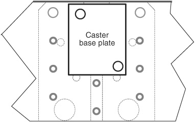
Figure 12-9 Mounting location for the balancing caster. Drill holes in the TinBot base according to the specific spacing of the caster you use.

Figure 12-10 Assembly detail for attaching the caster to the base. The spacer (you may also use a stack of three or four washers) is recommended if you use a caster with a wheel diameter under 1-1/2″.
Using the TinBot
As noted at the start of this chapter, R/C servo motors require a unique control signal in order to power them. They will not work simply by connecting them to a battery. See Chapter 23, “Using Servo Motors,” for more details on their operation.
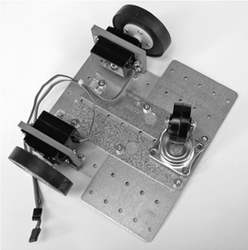
Figure 12-11 The underbelly of the TinBot, showing mounted motors and caster.
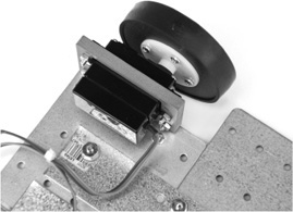
Figure 12-12 Close-up of the servo in its mount.
Also see the chapters in Part 7 for working examples of using servo motors with several popular microcontrollers. These are miniature programmable computers that, among other things, can be adapted to run servos.
The TinBot has adequate room on both the top and the bottom of its metal plates for mounting batteries, electronics, and other components. The plates already have holes in them, which you can use to mount things. At worst, you can use one hole already there and drill a second hole if the existing spacing doesn’t match the component you’re adding.
![]()
Because the TinBot is made of metal, and metal conducts electricity, be especially careful how you mount your electronics. Never ever allow bare wires, component leads, or the underside of circuit boards to touch the metal, or your robot parts may be irreparably damaged.
As necessary, use plastic washers (and plastic fasteners) to keep things physically separate from the metal base. Or lay down a thin sheet of plastic to act as an insulator. Every time you use your TinBot, visually inspect that there are no short circuits.
Do this prior to connecting your TinBot electronics to the battery and turning things on. Or else … poof! “Poof” is bad, so avoid it at all costs.