
Chapter 15
Drafting Bots with Computer-Aided Design
Your robot may operate under its own power, but you probably designed and made it by hand. You can streamline the construction process by using computer-aided design, or CAD. Using nothing more than your own computer, a free or low-cost CAD program, and a printer, you can try out different designs before you ever plug in that saw.
In this chapter you’ll learn about creating designs and construction layouts, first by hand (so you can see the process), and then by computer. And with a computer layout, you can even ship off your design files to a service, where they’ll make the parts for you. Sounds expensive? You’d be surprised. Anyway, let’s get started.
FYI
This chapter concentrates on mechanical design. A form of CAD is also used for making printed circuit boards, used in constructing robot electronics. That topic is covered separately, in Chapter 33, “Making Circuit Boards.”
Making Drilling and Cutting Layouts
Everything goes better when you have a plan.
Producing drilling and cutting layouts by hand takes less time, but using a computer graphics program makes changes a snap. For example, with a computer it’s easy to make the layout slightly smaller or larger, in case you want to adjust the size.
CREATING LAYOUTS BY HAND
The straightforward method of producing robot layouts is to hand draw them. The drawing can be directly on the part itself or onto paper. You can then attach the paper to the material.
Direct Layout
Mark the material with the layout you want using a soft pencil. A construction pencil, which you can find in the tool section of your local hardware store, has a very soft lead and writes on most any surface, including plastic, metal, and even tile (TileBot anyone?). You can also use a fine-tipped black marker such as a Sharpie.
Paper Layout
Drawing the layout on paper then using the paper as a template is a lot more forgiving. If you make a mistake it’s easy just to start again with a new piece of paper. Use a sheet of ordinary unlined white paper. If the sheet is too small, you can use white craft paper, available in rolls at a craft or discount store.
With a pencil, draw the layout on the paper. A ruler or other drafting aid will help in making straight, accurate lines. If you wish, you can use graph paper (1/4″ grid) to help with the layout.
When done, fix the paper template directly to the material, like that in Figure 15-1. Use tape, a glue stick, or other temporary adhesive to hold the paper in place. Use the layout to punch pilot marks prior to drilling.
After cutting and drilling is completed, peel the paper away from the material. For plastic and metal, any adhesive residue that is left can be cleaned off using denatured alcohol. For wood, the adhesive can be removed by a light sanding.
Making Multiple Parts
Paper templates make it easy to make more than one copy of the same part. Here are two methods you can try, depending on the type and thickness of the material you’re using:
![]() Draw the layout once, then have it copied on a plain paper copier. Attach each copy to the piece of wood, plastic, or metal you’re using for your robot. Be sure the copier reproduces the images at 100 percent by holding up the original and copy to a light and noting any misalignment. Some copiers automatically apply a 2 percent (or so) reduction, and this can be compensated for on better copiers by slightly enlarging the image.
Draw the layout once, then have it copied on a plain paper copier. Attach each copy to the piece of wood, plastic, or metal you’re using for your robot. Be sure the copier reproduces the images at 100 percent by holding up the original and copy to a light and noting any misalignment. Some copiers automatically apply a 2 percent (or so) reduction, and this can be compensated for on better copiers by slightly enlarging the image.
![]() Make just a single copy, and use it to cut out multiple pieces at a time. Stack the material like layers on a cake. Drill and cut through all of them at once. This method works best when you’re using thin materials, such as 1/8″ expanded PVC or hardwood plywood.
Make just a single copy, and use it to cut out multiple pieces at a time. Stack the material like layers on a cake. Drill and cut through all of them at once. This method works best when you’re using thin materials, such as 1/8″ expanded PVC or hardwood plywood.
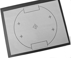
Figure 15-1 A paper template serves as a cutting and drilling guide for making any kind of robot base. Just be sure to print the template to exact size. Attach the paper using Glue Dots or other nonpermanent adhesive.
Using Transfer Paper and Scribes
Sometimes you can’t (or don’t want to) physically stick the paper to the material. You can use transfer paper instead. It works just like old-fashioned carbon paper, but it isn’t as messy. Trace the design on the paper using a ballpoint pen. The tracing will appear through the transfer paper. Unwanted transfer lines can be removed with a soft pencil eraser. Find transfer paper at art supply stores.
For materials with a rough or irregular surface, the pattern can be transferred using a scribe. A machinist’s scribe is the appropriate tool for the job, but these can be expensive. Most any sharp metal implement, such as a scratch awl or nail (with its tip sharpened) will work with plastics, aluminum, and other soft metals.
CREATING LAYOUTS WITH COMPUTER GRAPHICS PROGRAMS
Whatever you can do with a paper layout by hand, you can do better with a computer graphics program. You can create and store your layouts for future use, share them with others, and, given the right kind of program, make tweaks and changes for quick updates.
There are two general types of graphics programs: bitmap and vector. The difference is how the program stores the shapes you draw.
![]() Bitmap graphics is composed of a series of dots, like the dots in a newspaper picture. Windows Paint is a good example of a bitmap graphics program. Pick a drawing tool, and it creates a swath of dots in some distinct shape, size, and color.
Bitmap graphics is composed of a series of dots, like the dots in a newspaper picture. Windows Paint is a good example of a bitmap graphics program. Pick a drawing tool, and it creates a swath of dots in some distinct shape, size, and color.
![]() Vector graphics is composed of lines and other shapes. You make drawings by combining different shapes—squares, rectangles, lines, and so on—together. See Figure 15-2 for an example.
Vector graphics is composed of lines and other shapes. You make drawings by combining different shapes—squares, rectangles, lines, and so on—together. See Figure 15-2 for an example.
Changes are harder with bitmap graphics, because once the bits for a shape are laid down on the digital canvas, the shape itself can no longer be edited. On the other hand, with a vector graphics program you can directly change any of the shapes, even delete them. Changes are much easier.
Vector Graphics Best Choice
Of the two, vector graphics programs are by far the most useful in drafting your robots. You can use the program to create the overall design—basically a drawn picture of how your robot will look when finished. Or you can use the program to create drill and cutout templates—the same idea but better execution to layouts drawn by hand.
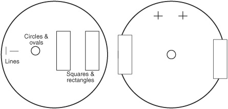
Figure 15-2 Prepare a construction template using simple shapes by combining circles, squares, rectangles, and lines.
You might already have a vector graphics program handy—even Microsoft Word comes with vector drawing tools. But there are plenty of free and open-source vector graphics applications you can try, and some are better suited for robot building. These include Inkscape, which has become something of an industry standard, and Google Sketch (available free or paid; the free version is good enough for most tasks.)
Using Inkscape for Robot Design
Inkscape serves as a good reference for using a vector graphics program to design robots. Figure 15-3 shows the Inkscape program window. Here’s a rundown of the important parts of the program interface.
Menu bar and tool bars: These control the program using commands in menus and on various toolbars.
Canvas: Your drawing goes in the middle portion, the canvas. Zoom controls let you see your drawing from a distance or up close.
Drawing tools: You create or edit the drawing using this small selection of tools on the left side of the screen. Vector graphics programs like Inkscape are based on what’s known as Bezier curves, whereby any shape is composed of one or more lines. Each line can be bent into sharp or smooth curves—a circle is really a line that bends back to itself.
Color palette: Solid shapes and their lines can be filled with color using a handy palette of preset shades, located at the bottom of the screen. Millions of other colors can be set using specialized tools.

Inkscape also supports writing text on your drawings. Use the text tool to label parts or provide dimensions. Inkscape lacks features for automatically inserting dimensions (this is more the domain of a CAD program; see the next section), but you can readily add the text yourself.
Figure 15-4 shows a drill and cutting layout created in Inkscape using just simple shapes. A circle is used to define the shape of the robot’s base, and rectangles indicate cutouts for motors. Small circles with thin crosshair marks show where holes go, and the size of the circles indicates the approximate diameter of the holes.
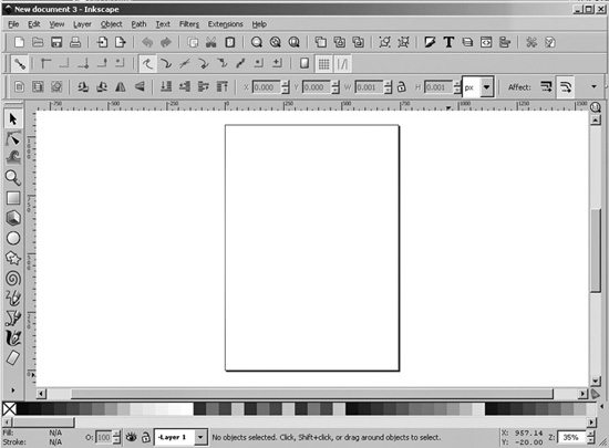
Figure 15-3 Inkscape (available for Windows, Macintosh, and Linux) is free software for creating and printing vector graphics. Its interface is simple and easy to learn.
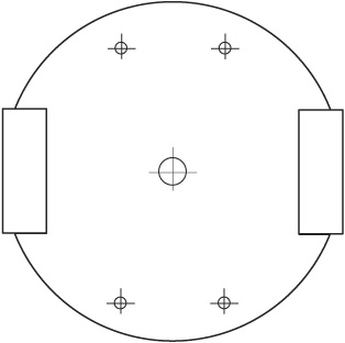
Figure 15-4 The cutting and drill template shown in Figure 15-1 created by Inkscape and then printed to scale.
To use the template, just print it out, then tape or transfer it to the material used for your base. Use the same techniques detailed previously under “Creating Layouts by Hand.”
MAKING LAYOUTS WITH LOW-COST CAD PROGRAMS
Another way to produce layouts for your robot projects is with a computer-aided design (CAD) program. CAD is like a vector graphics program, but it also combines mechanical drafting features. The idea behind CAD is that not only can you draw a square, you can draw a square that is precisely 1″ by 2″. Absolute measurements are stored with the CAD file and, when used with the appropriate printer, produce highly accurate renditions of your drawings.
CAD programs are often referred to as 2D or 3D. A 2D CAD program can create a two-dimensional drawing. The layout on the drawing has height and width, but no depth. This is the kind you use to produce layouts for cutting and drilling.
A 3D program can create a three-dimensional drawing that has height, width, and depth. Most 3D CAD programs can “render” 3D shapes using complex lighting and shading options. 3D CAD is not required for producing basic robot layouts, but can be used to visualize or document its construction.
AutoCad, from AutoDesk, is perhaps the best-known CAD program. As with most commercial CAD software, AutoCad is frightfully expensive. If you’re a student, you may qualify for a discount.
An alternative is a free or low-cost CAD program. Several are available for download from the Internet. While they may not compare with high-end commercial products like AutoCad, they are more than sufficient for our application.
A leader in low-cost but capable CAD programs is TurboCAD. It’s available in different editions, with both low-end and high-end versions—pick the consumer-oriented Deluxe version, as it’s a lot less expensive than the Pro version. Figure 15-5 shows a simple drill and cut template designed in TurboCAD. The template is meant to be printed as is and pasted to a sheet of wood, plastic, or metal.
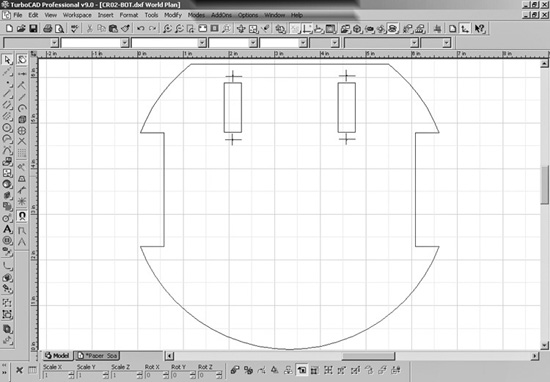
Figure 15-5 Sample cutting and drilling template created in TurboCAD, one of many CAD (computer-aided design) programs for precision drawing. It’s available in low-cost consumer versions.
Benefits of CAD
There are several benefits of using a CAD program to create cutting and drilling layouts.
Accuracy: With CAD, it’s relatively easy to draw shapes with the exact size you want. No more guessing. You can precisely control both the size of lines, circles, and other objects and their spacing relative to one another. This can be done using the sizing and dimensioning tools, and with snaps, where drawn objects conform to known sizes and boundaries.
Drawing automation: If you need to produce a series of 20 holes around the circumference of a 6″ circle, for example, tools provided by the CAD program make this easy.
Editability: Designs can be readily and quickly altered, in case you need to make adjustments. While some refinements can be made “on the fly” as you work with the finished robot, you may also wish to go back to the original design, make changes, and start over again.
Automated construction: A fourth benefit applies when using a computer-controlled mill or other machine to construct the pieces you design. The drawing you produce with the CAD program can be used directly to build the finished part. Most software for computer-controlled manufacturing can read DXF files, which is a commonly supported file format of 2D CAD programs. See “File Formats for Vector Graphics” for more details on graphic formats.
Not many people own their own computer-controlled mill, but you can always send your drawings to a service bureau and have them use their machines to make your parts. See “Using Laser Cutting Services,” later in this chapter. Unless you plan to market your robot product, it’s more affordable to send out parts to be manufactured.
Basic CAD Functionality
Most CAD programs require something of a steep learning curve to discover how to use its features. But basically, and for our purposes, the functionality of the program can be narrowed down to the following:
![]() Drawing setup. Here you define the drawing size and drawing scales (e.g., 1:1, 1:12, etc.), unit of measurement, as well as grid size and drawing resolution. For most robotics projects, you’ll want a 1:1 scale, a grid of 1/4″ or 1/8″, and a resolution of 2-or 3-decimal places—that is, down to the hundredths or the thousandths of an inch.
Drawing setup. Here you define the drawing size and drawing scales (e.g., 1:1, 1:12, etc.), unit of measurement, as well as grid size and drawing resolution. For most robotics projects, you’ll want a 1:1 scale, a grid of 1/4″ or 1/8″, and a resolution of 2-or 3-decimal places—that is, down to the hundredths or the thousandths of an inch.
![]() Drawing tools. Only a few shapes are used for typical robot layout drawings: line (and/or polyline), circle, and rectangle. Lines are used to mark cutting layouts. A polyline is a set of lines that share at least two vertices (corners), and it is used whenever you want to cut out more complex shapes. Circles are typically used to denote holes for drilling. A rectangle or square is a closed polyline shape and can be produced using the line, polyline, or rectangle tool.
Drawing tools. Only a few shapes are used for typical robot layout drawings: line (and/or polyline), circle, and rectangle. Lines are used to mark cutting layouts. A polyline is a set of lines that share at least two vertices (corners), and it is used whenever you want to cut out more complex shapes. Circles are typically used to denote holes for drilling. A rectangle or square is a closed polyline shape and can be produced using the line, polyline, or rectangle tool.
![]() Editing/sizing tools. You can adjust the size and look of the shapes by using the mouse or by entering values at a command-line prompt. The mouse is good for “eyeballing” the design, but the command-line entry is handy when you need accurate placement.
Editing/sizing tools. You can adjust the size and look of the shapes by using the mouse or by entering values at a command-line prompt. The mouse is good for “eyeballing” the design, but the command-line entry is handy when you need accurate placement.
![]() File saving/printing. Once done with the drawing, you can save it for future use or print it out. Any supported printer will do, such as a laser or ink-jet printer. CAD programs don’t have to be used only with pen plotters anymore.
File saving/printing. Once done with the drawing, you can save it for future use or print it out. Any supported printer will do, such as a laser or ink-jet printer. CAD programs don’t have to be used only with pen plotters anymore.
![]() Drawings are placed on a workplane. With 2D CAD, a simple X and Y coordinate system is used to denote the origin (the start point in virtual space) of the drawing. With most CAD programs the origin is the lower-left corner of the drawing and is denoted as 0,0. The first digit is the X axis; the second digit is the Y axis.
Drawings are placed on a workplane. With 2D CAD, a simple X and Y coordinate system is used to denote the origin (the start point in virtual space) of the drawing. With most CAD programs the origin is the lower-left corner of the drawing and is denoted as 0,0. The first digit is the X axis; the second digit is the Y axis.
File Formats for Vector Graphics
You’re probably familiar with GIF, JPG, and PNG graphics files. These are all bitmap file formats and typical of images you see on Web sites. Each is a different data format and, by convention, the specific format is used as the filename extension—a file named myrobot.jpg is a JPG bitmap of someone’s robot.
Likewise, vector graphics have their own file formats. As many were created for a special purpose or graphics program, they tend to be unique to themselves and often are not compatible with one another (you can sometimes use a converter program to exchange one format for another, but the results can leave much to be desired).
Of the varied vector graphics formats, these that follow are the most common, and the ones you’ll likely work with and share with others.
![]() SVG—Scalable Vector Graphics, now the uber-standard for vector-based images, and supported by Wikipedia. This is Inkscape’s default file format.
SVG—Scalable Vector Graphics, now the uber-standard for vector-based images, and supported by Wikipedia. This is Inkscape’s default file format.
![]() EPS—Encapsulated PostScript is an interchange format promoted by Adobe. It contains definitions of the graphic elements as PostScript command codes, plus (usually) a medium-resolution bitmap for use by those programs that can only import a bitmap. Programs have varying support for EPS, and some—like Inkscape—need additional plugins to understand the format.
EPS—Encapsulated PostScript is an interchange format promoted by Adobe. It contains definitions of the graphic elements as PostScript command codes, plus (usually) a medium-resolution bitmap for use by those programs that can only import a bitmap. Programs have varying support for EPS, and some—like Inkscape—need additional plugins to understand the format.
![]() AI—The native file format for Adobe Illustrator, AI is one of the premier commercial vector graphics applications. Saving and sharing this format is acceptable as long as everyone has Illustrator and, better yet, similar versions. Otherwise, use SVG.
AI—The native file format for Adobe Illustrator, AI is one of the premier commercial vector graphics applications. Saving and sharing this format is acceptable as long as everyone has Illustrator and, better yet, similar versions. Otherwise, use SVG.
![]() DXF—The Drawing Exchange Format is most commonly found on CAD programs and was originally developed by AutoDesk to allow AutoCad to share its 2D files with other applications. It’s now become a de facto standard for all CAD apps.
DXF—The Drawing Exchange Format is most commonly found on CAD programs and was originally developed by AutoDesk to allow AutoCad to share its 2D files with other applications. It’s now become a de facto standard for all CAD apps.
![]() DWG—Like DXG, the Drawing format is used for interchange with CAD programs and is primarily intended for 3D graphics. It’s not as widely supported as DXF.
DWG—Like DXG, the Drawing format is used for interchange with CAD programs and is primarily intended for 3D graphics. It’s not as widely supported as DXF.
File formats common in some 3D CAD programs include SAT, STEP, IGES, and INV. Not all CAD programs can open them. If you share your designs with others, be sure everyone has the same CAD program or can open the files without significant loss of information.
Using Laser-Cutting Services
See that cutting and drilling template in Figure 15-4? Because it’s made to exact scale, you could use the drawing to have your robot base professionally produced with a laser cutter. Laser cutters use a high-intensity pencil-thin light beam to make precision holes and cuts in wood, plastics, and even some metals.
Cost varies depending on the amount being cut and the type and thickness of the material, but it’s less expensive than most people think. It’s a good alternative if you have a complex design and need the precision that hand-cut parts can’t provide.
Not all services cut every material. Most will accept cardboard, plywood, acrylic plastic, polystyrene, and polycarbonate plastic. Laser cutters generally won’t accept jobs involving aluminum or expanded PVC, as working with these materials can damage their machines.
Custom laser-cutting services can be found locally as well as online. Do a Web search for laser cutting. If you’re only interested in local services, online business directories (Yellow Pages, Yellow Book, and so on) will help you narrow your search to those near you.
Some tips:
![]() Be sure to read and understand the instructions for submitting files. Most laser cutters prefer files using the DXF format (these have a .dxf extension). Any self-respecting CAD or vector graphics program can save files in this format.
Be sure to read and understand the instructions for submitting files. Most laser cutters prefer files using the DXF format (these have a .dxf extension). Any self-respecting CAD or vector graphics program can save files in this format.
![]() Use just one line thickness. Don’t use a “fill” on any of the shapes. Holes should be circles; the hole will be the diameter of the circle.
Use just one line thickness. Don’t use a “fill” on any of the shapes. Holes should be circles; the hole will be the diameter of the circle.
![]() The lower left of your drawing should start at 0,0. No part of your drawing should go below the 0 marks, or it may not be cut.
The lower left of your drawing should start at 0,0. No part of your drawing should go below the 0 marks, or it may not be cut.
![]() In all CAD and vector graphics programs, the shapes (objects) of the drawing are stacked one on top of the other on the canvas workplane. The stacking order of these objects matters: the cutter will start with the objects at the bottom and finish with those on the top. When cutting out a base, you want the outline of the base to be cut last. See the manual for your CAD/vector program to learn how to manipulate the order of objects on the workplane.
In all CAD and vector graphics programs, the shapes (objects) of the drawing are stacked one on top of the other on the canvas workplane. The stacking order of these objects matters: the cutter will start with the objects at the bottom and finish with those on the top. When cutting out a base, you want the outline of the base to be cut last. See the manual for your CAD/vector program to learn how to manipulate the order of objects on the workplane.
Producing “Quick-Turn” Metal and Plastic Prototypes
Thanks to computer automation, you can now quickly and affordably design and produce parts for your robot out of metal or plastic. The concept is called quick-turn prototyping, and it takes the idea of laser cutting to the next level. Using approved CAD software, or a graphics program that the prototyping service provides, you design your part, then submit it to them for manufacture. They then produce the part—usually within a few days—on their automated equipment.
Common parts for quick-turn prototyping include your own motor or servo brackets, custom gripper components, and even complete robot bodies. Aluminum is widely used in quick-turn manufacturing, because it can be machined, cut, and bent on automated (and partly automated) machinery.
A variation on the theme is using 3D printers, where liquid ABS, acrylic, or polycarbonate plastic is squirted in precise, measured amounts as a “print head” zigzags back and forth. On each zig and zag, a 3D shape is formed bottom to top. 3D printing is also known as additive manufacturing, RepRap (after a popular open-source project by that name), and FDM, which stands for Fused Deposition Modeling.
To turn your ideas into 3D shapes, you need to start with 3D CAD software (SolidWorks is popular with many quick-turn manufacturers) or some other mainstream program. Or you may be expected to use the proprietary modeling software provided by the quick-turn service shop.