
Chapter 26
Build Robots with Wheels and Tracks
As you discovered in Part 2 of this book, you can construct practical and functional mobile robots using only common tools and readily available materials. You can use wood, plastic, or metal—or, for quick prototypes, heavy-duty cardboard or foamboard intended for art projects. (What’s a robot but a fancy art project?!)
This chapter extends what you’ve discovered in previous pages, offering numerous plans and design concepts for building robots that run about on wheels and tracks. The choice of construction material is up to you, and you’re free to experiment with different sizes and assembly techniques.
See Chapter 27 if you’re wanting to build a robot that uses legs to move around.
FYI
See also Chapters 20 through 23 for information on general robot design, as well as information on powering your robot with motors. And be sure to check out the free bonus projects on the RBB Online Support site, detailed in Appendix A.
Basic Design Principles of Rolling Robots
With few exceptions, bots that roll use wheels or tank treads to get from one place to another. As you read in Chapter 20, “Moving Your Robot,” wheeled robots use a number of steering techniques. The most common—for wheels or treads—is two motors on each side of the vehicle.
DRIVE MOTOR ARRANGEMENTS
The most popular mobile robot design uses two identical motors to spin two wheels on opposite sides of the base. These wheels provide forward and backward locomotion, as well as left and right steering. If you stop the left motor, the robot turns to the left. By reversing the motors relative to one another, the robot turns by spinning on its wheel axis (“turns in place”). You use this forward-reverse movement to make “hard” or sharp right and left turns.
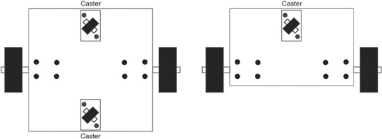
Figure 26-1 Center- versus front-drive motor mounting. With the center-drive arrangement, you typically need a caster on each end, though you can use just one if the robot is properly balanced.
Centerline Drive Motor Mount
You can place the wheels—and, hence, the motors—just about anywhere along the length of the platform. If they are placed in the middle, as shown in Figure 26-1, you should add casters to either end of the platform to provide stability. Since the motors are in the center of the platform, the weight is more evenly distributed across it.
A benefit of centerline mounting is that the robot has no “front” or “back,” at least as far as the drive system is concerned. Therefore, you can create a kind of multidirectional robot that can move forward and backward with the same ease. Of course, this approach also complicates the sensor arrangement of your robot. Instead of having bump switches only in the front of your robot, you’ll need to add some in the back in case the robot is reversing direction when it strikes an object.

Depending on the size of the robot and its weight distribution, you may be able to get by with just one caster. By placing slightly more weight over the caster, the bot will favor tipping to that side.
Front-Drive Motor Mount
You can also position the wheels on one end of the platform. In this case, you add one caster on the other end to provide stability and a pivot for turning, also shown in Figure 26-1. Obviously, the weight is now concentrated more on the motor side of the platform. Even out the weight distribution by putting the batteries in the center of the platform.
One advantage of front-drive mounting is that it simplifies the construction of the robot. Its “steering circle,” the diameter of the circle in which the robot can be steered, is still the same diameter as the centerline drive robot. However, it extends beyond the front/back dimension of the robot. This may or may not be a problem, depending on the overall size of your robot and how you plan to use it.
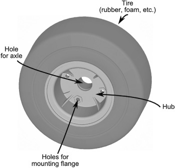
Figure 26-2 The construction of the typical wheel is a rubber (or other material) tire mounted on a hub.
PICKING THE RIGHT WHEELS
Wheels are made up of tires (or tyres, in the United Kingdom), mounted on hubs (Figure 26-2). A tire is rubber, plastic, metal, or some other material, and the hub is the portion that attaches to the shaft of the axle or motor. The hub usually has a hole for an axle, which is most often the driveshaft of a motor.
Some wheels for robots are molded into one piece. Others, such as the Dave Brown Lite-Flight wheels, are composed of separate pieces assembled at the plant. The Lite-Flight wheels use a plastic hub that attaches to the motor shaft or axle, and onto the hub is mounted a foam tire.
Wheel Materials
The first order of consideration is the materials used for the wheel. The least expensive wheels, like those used on low-cost toys, are molded in one piece, usually a hard plastic. The wheel doesn’t have a separate tire and hub. While these wheels are acceptable for some robots, you probably want a softer tire surface. This requires a softer rubber or foam, over a rigid hub.
Rubber over plastic: The hardness of the rubber greatly influences traction. One common measure of hardness is the Durometer, tested by a device called (get this!) the durometer. There are several durometer scales, each labeled with a letter, such as A or D. A Durometer of 55A is relatively soft and pliable; 75A is medium, and 95A is quite hard.
Rubber over metal: Typical of wheels made for R/C racing, these are heavier and sturdier, and are well suited to bigger robots. You can also get small rubber tires mounted on aluminum hubs. These are typically sold at hobby stores as tail wheels for model airplanes.
Foam over plastic: Foam wheels are also a mainstay in the R/C racing field. Like their rubber counterpart, hardness varies.
Rubber/foam over spoked wheels: As the size of the wheel increases, so does its weight. Spokes are used to reduce the weight of very large wheels. Smaller bicycle or wheel-chair wheels are suitable for larger robots.
Pneumatic wheels: Traditional foam and rubber tires are merely fitted over their hubs. In a pneumatic wheel, the tire is filled with air, which gives the wheel more bounce, but with added rigidity. Wheels for wheelbarrows and some wheelchairs are pneumatic.
Airless tires: Similar in concept to the pneumatic wheel, airless tires are hollow and filled not with air but with a rubber or foam compound. They are common on wheelchairs and heavy-duty materials-handling carts. They’re great for larger bots that have to carry a lot of weight.
Wheel Diameter and Width
There are no standards among wheel sizes. They vary by their diameter, as well as their tread width (the tread is the plastic, foam, or rubber material that contacts the ground).
![]() The larger the diameter of the wheel, the faster the robot will travel for each revolution of the motor shaft. You can quickly calculate linear speed if you know the speed, in revolutions per minute or second, of the motor. Simply multiply the diameter of the wheel by pi, or 3.14, then multiply that result by the speed of the motor. See the section “Using Wheel Diameter to Calculate the Speed of Robot Travel” for more details.
The larger the diameter of the wheel, the faster the robot will travel for each revolution of the motor shaft. You can quickly calculate linear speed if you know the speed, in revolutions per minute or second, of the motor. Simply multiply the diameter of the wheel by pi, or 3.14, then multiply that result by the speed of the motor. See the section “Using Wheel Diameter to Calculate the Speed of Robot Travel” for more details.
![]() The larger the diameter of the wheel, the lower the torque from the motor. Wheels follow the laws of levers, fulcrums, and gears. As the diameter of the wheel increases, the amount of torque delivered by the wheel decreases.
The larger the diameter of the wheel, the lower the torque from the motor. Wheels follow the laws of levers, fulcrums, and gears. As the diameter of the wheel increases, the amount of torque delivered by the wheel decreases.
![]() Wider wheels provide a greater contact area for the wheel, and therefore traction (from friction) is increased.
Wider wheels provide a greater contact area for the wheel, and therefore traction (from friction) is increased.
![]() The wider the wheels, the more the robot will tend to stay on course (called tracking). With narrow wheels, the robot may have a tendency to favor one side or the other when there is even the slightest misalignment of the wheels. Conversely, if the wheels are too wide, the friction created by the excess wheel area contacting the ground may hinder the robot’s ability to make smooth turns.
The wider the wheels, the more the robot will tend to stay on course (called tracking). With narrow wheels, the robot may have a tendency to favor one side or the other when there is even the slightest misalignment of the wheels. Conversely, if the wheels are too wide, the friction created by the excess wheel area contacting the ground may hinder the robot’s ability to make smooth turns.
When selecting the wheel diameter and width, match the wheel to the job. A robot with modest-size wheels of fairly narrow proportions (say, 1/4″ wide for a wheel of 2.5″ to 3″ in diameter) will be more agile than if it were equipped with much wider wheels.
Wheel Placement and Turning Circle
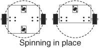
Where the wheels are located on the robot base affects the turning circle of the robot. Whenever possible, locate the wheels within the body of the base, rather than outside it. This decreases the effective size of the robot and allows it to turn in a tighter circle. Figure 26-3 shows wheels mounted both within the area of the base and outside it.
UNDERSTANDING WHEEL TRACTION
As in a car, wheels on your robot are meant to grip the driving surface. This provides traction and allows it to move forward. Yet, oddly enough, with robots both too little and too much grip can be a bad thing.
Picking up from Chapter 20, “Moving Your Robot,” let’s look at how a differentially steered robot is designed. It has two motors and wheels mounted on opposite sides. Traction going straight ahead is simple: when both motors are activated in the same direction, the robot moves forward or backward in a straight line.
Wheel traction becomes an issue in turns. There are two ways to turn a differentially steered robot: by reversing the motors relative to one another (hard turn) or by stopping one motor and activating the other (soft turn). In both kinds of turns,

Figure 26-3 The turning circle describes the area occupied by a robot when it makes a spinning turn. Given the same-diameter base, wheels on the inside of the base circumference have a smaller turning circle.
![]() Inadequate traction causes the wheels to slip, so it’s anyone’s guess where the robot will be heading afterward.
Inadequate traction causes the wheels to slip, so it’s anyone’s guess where the robot will be heading afterward.
![]() Excessive traction can cause “chatter”—the wheels grip the road surface so well, they have to bounce in order to negotiate the turn. The effect is most pronounced in soft turns and is compounded in 4- and 6-wheel designs.
Excessive traction can cause “chatter”—the wheels grip the road surface so well, they have to bounce in order to negotiate the turn. The effect is most pronounced in soft turns and is compounded in 4- and 6-wheel designs.
![]() Four or more driven wheels, mounted in sets on each side, will function much like tank tracks. In tight turns, the wheels will experience significant friction and skidding. If you choose this design, position the wheel sets closer together.
Four or more driven wheels, mounted in sets on each side, will function much like tank tracks. In tight turns, the wheels will experience significant friction and skidding. If you choose this design, position the wheel sets closer together.
Most wheels for robotics use a rubber tire material. The softness of the rubber and its surface help determine its compliance. A very soft and mushy tire material—like that found on some model racing cars—may cause too much traction, hindering proper steering. A very hard tire material, such as a hard plastic, may not provide enough grip.
The effectiveness of any tire material is determined by the surface it rolls over. A hard tire on a hardwood floor can be a bad combination; a moderately soft tire on Berber carpet is a much better combination.
USING WHEEL DIAMETER TO CALCULATE THE SPEED OF ROBOT TRAVEL
The speed of the drive motors is one of two elements that determine the travel speed of your robot. The other is the diameter of the wheels. For most applications, the speed of the drive motors should be under 130 RPM (under load). With wheels of average size, the resultant travel speed will be approximately 4 feet per second. That’s actually pretty fast. A better travel speed is 1 to 2 feet per second (approximately 65 RPM), which requires smaller-diameter wheels, a slower motor, or both.
How do you calculate the travel speed of your robot? Follow these steps:
1. Divide the RPM speed of the motor by 60. The result is the revolutions of the motor per second (RPS). A 100 RPM motor runs at 1.66 RPS.
2. Multiply the diameter of the drive wheel by pi, or approximately 3.14. This yields the circumference of the wheel. A 7″ wheel has a circumference of about 21.98 inches.
3. Multiply the speed of the motor (in RPS) by the circumference of the wheel. The result is the number of linear inches covered by the wheel in 1 second.
With a 100 RPM motor and 7″ wheel, the robot will travel at a top speed of 36.49″ per second, or about 3 feet. That’s about 2 miles per hour! You can slow down a robot by decreasing the diameter of the wheel. By reducing the wheel to 5″ instead of 7″, the same 100 RPM motor will propel the robot at about 25 inches per second.
Bear in mind that the actual travel speed of your robot when it’s fully accessorized may be less than this. The heavier the robot, the larger the load on the motors, so the slower they will turn.
For your reference, here is handy table comparing travel speed, in inches per second, against a variety of motor RPM and several common small wheel sizes.
![]()
See the Robot Speed Calculator on the RBB Online Support site (refer to Appendix A). Enter the motor RPM and the diameter of the wheels you’re using, and the calculator tells you the travel speed in inches per second.
SUPPORT CASTERS AND SKIDS FOR WHEELED ROBOTS
Differentially steered robots need something on the front and/or the back to prevent them from tipping over. There are several common approaches, listed below.
Nonrotating Skid
The purpose of a skid is to glide over the ground without using any moving parts. The skid is rounded (a cap or acorn nut works well) to facilitate a smooth ride. Polished metal, hard plastic, or Teflon are common choices. For obvious reasons, skids are not suitable for robots that may travel over uneven surfaces or when there are many obstructions, like cables and old socks.
Swivel Caster
Swivel casters are available with wheel diameters from 1″ to over 4″. Match the size of the caster with the size of the robot. You’ll find the common 1-1/4″-to 2″-diameter caster wheel is suitable for most medium robots. For larger bases you can opt for the 3″ and even 4″ casters.
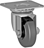
Swivel casters are commonly available with plate or stem mounting and in the following wheel styles:
• Single wheel
• Dual wheel (“twin wheel”)
• Ball style
The ball style is used with furniture and tends to be heavy. If you use it at all, reserve it for heavier robots. Single-wheel casters are the most common and easiest to find. Look for a caster that swivels easily.
Ball Caster
Ball casters act as omnidirectional rollers. Unlike swivel casters, which must rotate to point in the direction of travel, ball casters are ready to move in any direction at any time. This makes them ideal for use as support casters in robots.

The size of the ball varies from pea-sized to over 3″ in diameter, and they are available in steel, stainless steel, or plastic. Pololu sells a variety of small ball casters for desktop robots; industrial supply outlets such as Grainger, McMaster-Carr, and Reid Tool and Supply offer the bigger ones.
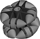
Omnidirectional Wheel
Omnidirectional wheels are basically rollers mounted on the tread of a tire. The tire turns on an axis like any other, but the rollers allow for movement in any direction. For what they do as casters, omnidirectional wheels mean extra cost, size, and weight. I’ve not found that they work any better than a ball transfer or even a well-made swivel caster.
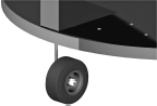
Tail Wheel
One alternative to the swivel caster is the tail wheel, used on R/C model airplanes (and, therefore, available at most hobby stores). The wheels come in sizes ranging from about 3/4″ to over 2″ and are used with specific mounting hardware.
In summary: For a small robot, under a couple of pounds and measuring 7″ in diameter or less, a nonrotating skid is usually acceptable. For centerline motor mounting, use two skids: one each in the front and rear of the bot. For larger or heavier robots, a skid may dig into soft surfaces, or it may snag on bumps, cables, and other obstructions. For these, use a swivel caster or a ball caster.
Successful Use of Casters
The casters on your robot must not impede the direction or speed of the machine’s travel. Cheap swivel casters can catch and not swivel properly when the robot changes direction.
Keep these points in mind when selecting and using casters with your robots:
![]() Test them for smooth swivel action. Casters with ball bearings tend to give better results.
Test them for smooth swivel action. Casters with ball bearings tend to give better results.
![]() In most cases, since the caster is provided only for support and not traction, the caster wheel should be a hard material to reduce friction.
In most cases, since the caster is provided only for support and not traction, the caster wheel should be a hard material to reduce friction.
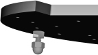
![]() When using two casters on either end of the base, there’s a possibility of the robot becoming trapped if the casters touch ground but the drive wheels do not. You can fix this by using only one caster instead of two, or place slightly more weight over the end with the caster. You may also reduce the height of the casters, or mount the casters on a spring suspension, as shown in Figure 26-4. Select a spring that, under normal load, just begins to compress from the weight of the robot.
When using two casters on either end of the base, there’s a possibility of the robot becoming trapped if the casters touch ground but the drive wheels do not. You can fix this by using only one caster instead of two, or place slightly more weight over the end with the caster. You may also reduce the height of the casters, or mount the casters on a spring suspension, as shown in Figure 26-4. Select a spring that, under normal load, just begins to compress from the weight of the robot.
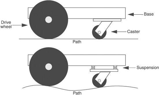
Figure 26-4 Spring-loading can overcome some of the common problems of using a caster over uneven terrain. The height of the caster adjusts to compensate for bumps.
Two-Motor BasicBot
The BasicBot is a simple differentially steered base that’s easy to construct of wood, plastic, cardboard, picture mat, or foamboard. It’s an ideal first robot, and its round shape makes it well suited for use as a wall follower, maze solver, or other robot that works in confined spaces. The base measures 5″ in diameter; many craft and hobby stores sell 1/8″- or 1/4″-thick wood and plastic already cut into this size (or close to it), saving you from cutting out a circle using a saw or mat-cutting blade. A finished BasicBot is shown in Figure 26-5.
The BasicBot uses the following motors and mechanical parts, all of which are available at Tower Hobby and many other online hobby stores (see Appendix B for Web sites).
![]() Tamiya Twin-Motor Gearbox, #70097. The motor comes as a kit and is assembled in about 20 minutes using a screwdriver and small needle-nose pliers.
Tamiya Twin-Motor Gearbox, #70097. The motor comes as a kit and is assembled in about 20 minutes using a screwdriver and small needle-nose pliers.
![]() Tamiya Ball Caster, #70144. You get two ball caster units; you need only one for the BasicBot, so save the second caster for another project. Construction takes about five minutes.
Tamiya Ball Caster, #70144. You get two ball caster units; you need only one for the BasicBot, so save the second caster for another project. Construction takes about five minutes.
![]() Tamiya Truck Tire Set, #70101. You get four tires; you need only two.
Tamiya Truck Tire Set, #70101. You get four tires; you need only two.
Tamiya also offers the model #70168 Double Gearbox kit. It is functionally identical to the Twin-Motor kit, except its dimensions are slightly different. This means that if you use the double gearbox you’ll need to adjust the drilling pattern in order to properly mount the motor to your robot base.
CONSTRUCTING THE BASICBOT
Refer to Figure 26-6 for the cutting and drilling layout. Use a 1/8″ bit to drill the holes. The location of the four holes on the base isn’t supercritical, but the spacing is. You may wish to use the constructed motor and ball caster to mark off the holes.
1. Begin by constructing the twin-motor gearbox according to the instructions that come with it. You have the choice of building the motors with a 58:1 or 203:1 gear ratio. Opt for the 58:1 ratio if you’d like a faster robot. For maze following and other tasks you’re better off with the slower, 203:1 ratio.
2. Before inserting the motors into the gearbox, solder wires to them and connect the wires to a set of switches or control electronics. See Chapter 22, “Using DC Motors,” for ways to control small motors.
3. Construct the ball caster according to the instructions that come with it. The caster comes with various pieces to alter its height. Your finished caster should measure about 1″ from the base to the ball socket.
4. Mount the motor box and ball caster. Assuming a 1/4″-thick base, use 4-40 × 1/2″ machine screws and nuts. You can use 3/8″-long screws if the base is 1/8″ thick.
5. Mount rubber tires onto two of the truck tires, then insert the wheels over the motor shaft. Figure 26-7 shows the underside of the BasicBot, with motor and ball caster attached.
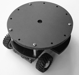
Figure 26-5 The BasicBot uses one or two decks, a Tamiya Twin Motor gearbox kit, a set of small tires, and a ball caster for balance. Construction takes less than an hour.
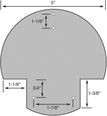
Figure 26-6 Cutting and drilling layout for the BasicBot. All holes are 1/8″.
ADDING A SECOND DECK
The one-deck BasicBot has room for a small microcontroller board, mini solderless breadboard, and a four-cell AAA battery holder. You can increase the area of the BasicBot if you need more space. Make a second deck with another 5″-diameter circle. Drill matching holes in both the bottom and the second deck. Use 1″- or 1-1/2″-long metal or plastic standoffs to act as “risers” to separate the two decks.
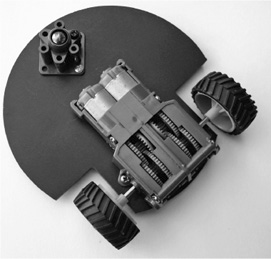
Figure 26-7 Underside of the BasicBot, showing the twin motor gearbox and ball caster.
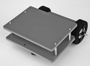
Figure 26-8 Completed RoverBot, constructed using only straight cuts. You can use wood, plastic, or metal for the body pieces. See the RBB Online Support site for full plans on constructing the RoverBot.
USING MORE EFFICIENT MOTORS
The Tamiya Twin-Motor kit makes for an affordable and easy-to-use motor set for small desktop robots, but these motors are not terribly efficient, and they consume a lot of current.
You can replace the DC motors used in the twin-motor kit with more efficient ones. The gearbox kit uses a pair of Mabuchi FA-130–size motors. You may substitute for a more efficient motor, as long as it conforms to the “130” motor size. Pololu and several other online sources offer replacement 130-size motors that consume much less current than the stock units that come with the Tamiya kit.
Bonus Project: Double-Decker RoverBot
Figure 26-8 shows a double-deck tabletop robot that I’ll call RoverBot. This base requires only rudimentary construction skills (straight cuts only) and can be made using a number of materials, including 1/4″-thick aircraft-grade plywood, 1/4″-thick expanded PVC sheet, or 1/8″ acrylic plastic. It’s designed to be easy to build and easy to expand.
This is a free bonus project available on the RBB Online Support site (see Appendix A). On the support site you’ll find complete construction plans, including cutting and drilling layouts, parts list and sources, and assembly instructions.
Building 4WD Robots
What’s better than a two-wheeled robot? Why, four wheels, of course! Four-wheel-drive (4WD) bots are able to traverse more kinds of terrain than their two-wheeled cousins, moving from indoors to out with ease. They’re the preferred method of exploring grassy or dirt areas. And because they have four wheels, 4WD robots are statically balanced and have no need (or use) for a caster. Like a 2WD robot, 4WD bases use differential steering to explore their world.
Alas, 4WD robots are a bit harder to construct, and, depending on how they’re designed, they cost more. But the advantages of a 4WD base often outweigh the disadvantages of a higher price tag and extra time in the shop.
What applies to the typical 4WD robot also applies to those using six (or more) wheels. As you add drive wheels, the complexity, weight, and cost of the robot can skyrocket. You might consider instead a tracked base, which functions like a multi-wheel-drive system, with an infinite number of wheels. See the following section for more on robots that use tracks.
SEPARATE MOTORS OR LINKED DRIVE?
While there are four-wheel-drive systems where two of the wheels are unpowered, in the typical 4WD all four wheels provide oomph to the robot. That means you either must use separate motors for each wheel or somehow link the wheels together so they’re driven by the same motors. Figure 26-9 shows the basic concept.
![]() Separate motors cost more but require less mechanical complexity. You merely add two more motors and wheels to the base. With separate motors you can also control them individually, which offers some benefits over loose terrain like unpacked dirt.
Separate motors cost more but require less mechanical complexity. You merely add two more motors and wheels to the base. With separate motors you can also control them individually, which offers some benefits over loose terrain like unpacked dirt.
![]() Linked drive saves the added cost of two extra motors, but requires you to develop a system where each motor powers two wheels at the same time.
Linked drive saves the added cost of two extra motors, but requires you to develop a system where each motor powers two wheels at the same time.
With either method, the wheels of the 4WD robot are the same diameter and are placed toward the center of the base. The farther apart the wheels on each side, the more difficult the steering. On many four-wheel-drive bots, the wheels are placed with only minimal separation.
Of the two, 4WD systems with separate motors provide the most power, simply because each motor is dedicated to a single wheel. On linked-drive systems, the one motor is shared between wheels, so the overall power of the base is less.
Constructing a Separate-Motor 4WD Robot
A simple yet fully functional 4WD robot can be built using three pieces of wood, plastic, or metal. The motors (let’s say, R/C servos) are mounted in what I call side rails. They’re just overgrown motor mounts, with cutouts for the body of the motor and holes for the screws. The side rails attach to a deck piece by way of any kind of corner angle bracket.
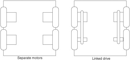
Figure 26-9 4WD robots take two general forms: those with four independent motors and those with two motors. The wheels on each side of the bot are linked to a single motor.

Figure 26-10 A 4WD robot, using servo motors and some oversized plastic wheels ripped off from a toy. The base is constructed by attaching the servos in side rails, and the side rails are attached to a top plate.
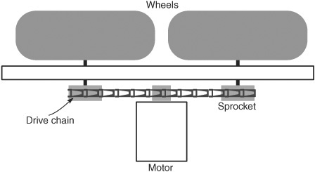
Figure 26-11 Chains (shown here) and belts can be used to link the wheels of a 4WD robot that uses only two motors. The chain allows for less precise construction requirements.
Figure 26-10 shows the basic concept of a 4WD base. The spacing between each pair of servo motors depends on the diameter of your wheels and the way the servos are mounted in the side rails (i.e., output shafts facing one another provide less space than if they face outward). In all, it’s a pretty straightforward design: mount the servos in side rails; stick the side rails to the base.
The choice of corner angle brackets is up to you. I used some plastic brackets I had lying around the shop, but the common 3/4″ × 1/2″-wide corner angle bracket available at any hardware store works as well.
On my prototype I used a set of six 4-40 × 1-1/2″ machine screws, along with some 5/8″ nylon standoffs I bought surplus, as risers between the bottom deck of the bot and an optional second deck. Holes are cut in the bottom deck to feed wires through for connecting to batteries, microcontroller, and other electronics.
Constructing a Linked-Drive 4WD Robot
A 4WD linked-drive system uses a single motor on each side of the robot and a power train coupling to connect each motor to its wheels. The most common techniques for coupling the motor and wheels are gear, chain, or belt drive.
![]() Belt and chain drive are probably the easiest methods, because both offer a bit of “slop” in aligning all the parts. A central motor (on each side of the bot) powers both wheels using either a flexible belt or a segmented chain; see Figure 26-11 for details. For best results, the belt should be cogged; that is, it should have nubs molded in that assertively mesh with teeth in the sprockets used on the motor and wheel shafts.
Belt and chain drive are probably the easiest methods, because both offer a bit of “slop” in aligning all the parts. A central motor (on each side of the bot) powers both wheels using either a flexible belt or a segmented chain; see Figure 26-11 for details. For best results, the belt should be cogged; that is, it should have nubs molded in that assertively mesh with teeth in the sprockets used on the motor and wheel shafts.
![]() Gear drive uses a main drive gear from the motor to mesh with subgears attached to the wheels (Figure 26-12). This is the method most commercially made 4WD toys use, but it requires extra precision when constructing a homebrew solution.
Gear drive uses a main drive gear from the motor to mesh with subgears attached to the wheels (Figure 26-12). This is the method most commercially made 4WD toys use, but it requires extra precision when constructing a homebrew solution.
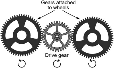
Figure 26-12 Gears used to transfer power from a central motor to a pair of wheels. The gears must be carefully positioned or else the teeth may not mesh properly.
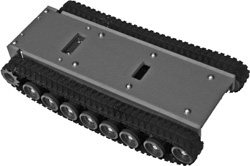
Figure 26-13 Tank-style robots use rubber, plastic, or metal treads, along with a drive motor and a series of unpowered idler wheels that keep the treads in place. Low-cost toys are a common source of useful rubber treads.
You must be very careful to align the gears with the proper spacing, or else they won’t mesh properly. The mechanism will bind if the gears are too close together, or slip and chatter if they’re too far apart.
For small robots (let’s say, under about 8″ to 10″), Tamiya makes several products that can be used to create belt- or chain-drive 4WD bases. First is the Tamiya Ladder-Chain Sprocket set (#70142), which consists of plastic molded sprockets and individual links of chain that you connect together. Add or remove links to make the chain the exact length you wish. Because of the parts assortment you get, you will need two complete sets for one robot base.
Another method is the Tamiya Track and Wheel Set (#70100), which comes with molded plastic sprockets and rubber 1″-wide tracks. This set is normally used to make a tracked vehicle (see later in this chapter), but it also works well as a belt-drive system for a 4WD vehicle.
Building Tank-Style Robots
Another popular form of the rolling robot is the tank tread design, so called because it uses treads (or tracks) similar to those on military tanks. Like 4WD robots, tank tread bots don’t need a balancing caster or skid. They use differential steering like 2WD and 4WD bases and are expressly designed for use over uneven terrain. Figure 26-13 shows a representative homebrew tracked-drive robot, made with a rubber tread stolen from a 1/8-scale tank toy and refitted over a plastic base.
FINDING THE RIGHT TANK TREADS
The first order of business is to locate a suitable tread or track for the tank-style robot. Common tread materials are rubber, plastic, and metal.
![]() Rubber treads are perhaps the most common, found (for example) on many tank and earthmover toys. You can rob the toy of its treads and other parts and use them on your robots.
Rubber treads are perhaps the most common, found (for example) on many tank and earthmover toys. You can rob the toy of its treads and other parts and use them on your robots.
![]() Plastic treads are made of rigid segments, linked together using pins or rivets. Several companies (Lynxmotion, Vex, JohnnyRobot) make plastic tracks for the express use as robot treads.
Plastic treads are made of rigid segments, linked together using pins or rivets. Several companies (Lynxmotion, Vex, JohnnyRobot) make plastic tracks for the express use as robot treads.
![]() Metal treads are found on high-end die-cast toys, as well as snowmobiles. These are heavy and expensive and are ideally suited for larger bots.
Metal treads are found on high-end die-cast toys, as well as snowmobiles. These are heavy and expensive and are ideally suited for larger bots.
Regardless of the material, the treads work in the same way: a drive sprocket positively engages with matching teeth or indentations in the tread. The tread is laid out along more or less the full length of the robot. Nonpowered idler sprockets or untoothed wheels keep the tread in place.
Each kind of track has its own unique method of engaging with its drive sprocket. Whenever possible, always purchase (or rob from a toy) a track with its corresponding sprockets and idlers.
BOTS WITH FLEXIBLE RUBBER TREADS
As noted, one of the best sources for inexpensive rubber tracks is toy tanks. These are sold in different scales, from about 1:64 (miniature) to upward of 1:10 or even 1:6. (The scale is the ratio of the size of the model to its original. A scale of 1:24, for example, means the model is 1/24 the size of the original. Most toy tanks are in the range of 1:24 to 1:32 scale.)
The robot in Figure 26-14 was constructed using rubber treads from a 1/10 (approximately) scale tank toy. The full circumference of the treads is about 26″, large enough to allow the unusual arrangement you see in the picture. The outside of the treads extends beyond the body of the robot, allowing it to flip over and still keep going. The robot can start to climb up a wall, and when it flips over, the motors immediately change direction. The robot doesn’t have to stop, back up, and steer around the wall.
Look for a toy where the track is not too elastic and where, at a minimum, the drive sprocket and idler rollers can be removed and placed on your own custom base. Some toy tanks offer easier hacking, where you can simply remove the turret and top of the vehicle, and replace the electronics with your own microcontroller and H-bridge. For these, you don’t need to build a body for your robot, as you have one ready-made in the toy itself.
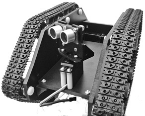
Figure 26-14 An invertible tank-type robot, capable of operating right side up or upside down. The treads and idler wheels were pulled from a remote control tank toy.
A good source for smaller rubber treads is LEGO Technic sets. The sets come with suitable sprockets that are made to engage with the teeth on the inside of the treads.
USING THE TAMIYA TRACK AND WHEEL SET
A commonly used track for robots is made by Tamiya and sold by itself as Tamiya Track and Wheel Set (item #70100). A number of online sources, such as Tower Hobbies and Hobby-linc, offer this set (see Appendix B, “Internet Parts Sources”). The track is also included in a few other Tamiya products, as the Tamiya Tracked Vehicle Chassis Kit and the Tamiya Remote Control Bulldozer Kit. These also come with motors.
The Tamiya track is rubber and comes in segments of various lengths. You put the segments together to build a track. Sprocket and idler rollers are included (see Figure 26-15). Pick out the parts you need. The segments connect using a little nub on the edges of the track. Despite how it sounds—or even looks—the tracks are fairly robust and seldom break apart unless forced.
In a pinch, you can glue the pieces together with a flexible adhesive, such as silicone caulk. Make sure the adhesive doesn’t seep into the part of the track that engages with the sprocket and that the seam is smooth.
Build an All-Purpose Tracked Robot Base
You can construct a practical and sturdy tracked robot base using two motors (DC gear or R/C servo) and a Tamiya Track and Wheel Set (#70100). The finished base is shown in Figure 26-16. Ideal construction materials are 1/4″ aircraft-grade birch plywood or 6mm expanded PVC.

Figure 26-15 Tamiya Track and Wheel Set, showing both plastic parts and rubber tread. You connect the tread in various lengths to suit the size of your robot.
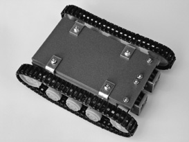
Figure 26-16 The All-Purpose Tracked Robot Base, using a couple of Tamiya gear motor kits and a Tamiya Track and Wheel Set. Construction is easy, and the whole thing costs under $25.
In addition to the base material you need:
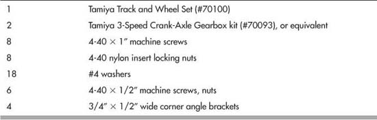
Begin by cutting out the base deck and side rail pieces as shown in Figure 26-17. Refer to Figure 26-18 for the drilling details for the two side rails (make two of these). Drill the holes using a 1/8″ bit. Hole placement is fairly critical, especially the distance between the two mounting holes for each motor, so use care.
Note the alternative mounting holes. These holes are for providing a higher tension for the treads. See the section “Tread Assembly” for more info.
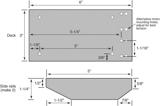
Figure 26-17 Cutting and drilling guide for the All-Purpose Tracked Robot Base. All holes are 1/8″.
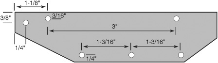
Figure 26-18 Drilling guide for the side rails for the All-Purpose Tracked Robot Base. All holes are 1/8″. Hole placement is fairly critical in order to maintain proper tension of the track. (Even so, you may need to re-tension the track as detailed in the “Tread Assembly” section.)
I’ve used a pair of Tamiya 3-Speed Crank-Axle Gearbox kits (#70093), as they are inexpensive and offer a choice of three different gear ratios: 17:1, 58:1, and 204:1. Normal speed is 204:1, but if you want a really fast tank, pick the 58:1 ratio.
Before construction, use a hacksaw or heavy-duty lineman’s pliers (be sure to wear eye protection!!) to cut the hex shaft to a length of 2-1/4″. Complete the assembly of the motors as described in the instruction sheet that comes with them. You’ll need a small Phillips screwdriver. Be sure to use the same gear ratio for both motors.
Prior to mounting the motors, use the included hex wrench to lightly tighten the setscrew that secures the driveshaft to its output gear. You need to make a “right” and a “left” motor, as shown in Figure 26-19. Position the drive shaft so there’s no more than 1/4″ protruding from the side of the motor.
Assembling the Side Rails
Refer to Figure 26-20 for the following. The side rails are what the tracks are attached to. Let’s begin with the left side rail.
1. Use a 4-40″ × 1″ screw, washer, and locking nut to attach the large idler wheel to the hole on the far left side of the rail. The wheel should face you. Tighten the locking nut so that the wheel just begins to stop turning freely, then back off about 1/8 of a turn. When you rotate the wheel there should be no drag. Neither should there be any kind of excessive wobble.
2. Use three more screws, washers, and nuts to attach the small idler wheels to the three holes along the bottom of the rail. Tighten them as you did the large wheel.

Figure 26-19 Motor construction and drive axle shaft placement for the All-Purpose Tracked Robot Base. You need to cut the axle shaft to length, using a saw or pair of heavy-duty lineman’s pliers (be sure to wear eye protection!).
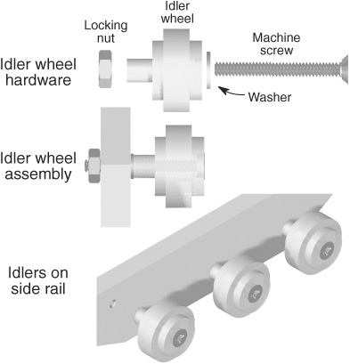
Figure 26-20 Construction detail for the idler wheels. Tighten the locking nut so the wheel just starts to drag, then back off the screw 1/8 turn.
3. Using 4-40 × 1/2″ screws, washers, and nuts, attach two corner angle brackets as shown in the illustrations.
Construct the right side rail in the same manner, but in mirror image.
Attaching the DC Gear Motors
Use 4-40 × 1/2″ screws and nuts to attach the two motors to the base. The short ends of the driveshafts should face each other.
Assemble the side rails to the base, using 4-40 × 1/2″ screws, washers, and nuts—see Figure 26-21. The motors are located at the rear of the base; the front should be flush with the leading edge of the right and left side rails.
Temporarily attach the large sprockets to the driveshafts. Using the hex key included with the motor, slightly loosen the setscrew that holds the driveshaft in place. As needed, move the driveshaft in the motor so that the sprocket lines up with the idler wheels in the side rail. Even a slight misalignment can cause the track to pop off when the robot turns, so try to be as accurate as possible. When done, tighten the setscrew on each motor.
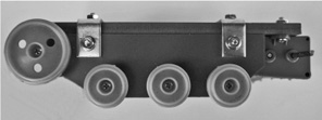
Figure 26-21 Edge view of the idler wheels attached to the All-Purpose Tracked Robot Base.
Tread Assembly
Assemble the treads from the Track and Wheel Set using the following lengths for each side:
![]() 1 each 30-links segment
1 each 30-links segment
![]() 2 each 10-links segments
2 each 10-links segments
![]() 1 each 8-links segment
1 each 8-links segment
The segments interlock into one another. Use only your fingers; avoid using mechanical force or tools to link the segments together, or else the rubber may get torn. It can take a few tries to get the hang of it. Refer to the instructions that come with the set for details.
To install the tread, loop over the four idler wheels. Wrap the tread around the teeth of the drive sprocket, and carefully push the sprocket onto the motor shaft. Note: Do not overstretch the tread or it may become unlinked.
The design of the All-purpose Tracked Robot Base allows for adjusting the tension of the track—important, because if the treads are too loose, they’ll pop off easily. Remove the motors, and drill new holes about 3/16″ away from the original set. Remount the motors.
You can create a slot for adjusting the track tension by drilling several holes close together in line. Use a thin rat-tail file to remove the material between the holes, thus making a slot.
Replacement FA-130 Motors
The miniature Mabuchi FA-130 motor included with the 3-Speed Crank-Axle Gearbox kit is not very efficient, consuming several amps when the motor is stalled (prevented from turning, but still powered). If you use electronic control to operate the motors, be sure it is rated for at least 2 amps, if not more.
Optionally, you can substitute the FA-130 for a higher-voltage, lower-current version. Pololu and several other online resources offer 130-size replacements that consume much less current and can be used with small motor bridge circuits. Consult Appendix B, “Internet Parts Sources,” for Web links.
Optional: Using Servo Motors
If you prefer, you may use an R/C servo to drive the tracked base. Mount the motor to the robot base using your favorite technique (see Chapter 24 for some suitable mounts you can make yourself). Then, interface the sprocket to the motor with these steps:
1. Cut off the molded-in cap on the side of the drive sprocket.
2. Drill out the center using a 1/4″ bit.
3. Drill out two holes in a small round servo disc to match two of the holes in the drive sprocket. It turns out the holes match exactly when using the small round servo disc that comes with most Futaba and Futaba-style servos.
4. As shown in Figure 26-22, attach the servo disc to the sprocket using a pair of 4-40 × 3/8″ machine screws and nuts.
5. Use the screw included with the servo to mount the drive sprocket to the motor.
Adding a Second Deck
Need more space? You can add a second deck to the tracked base by removing the nuts on the top of the corner angle brackets and replacing them with 4-40 threaded hex standoffs. Cut out the wood or plastic for the top deck, and secure it in place over the hex standoffs using 4-40 × 1/2″ screws.
BEST STEERING FOR TRACKED ROBOTS
Because a tank track exposes a considerable amount of its surface onto the ground at any one time, in a turn the tracks must actually slip, or skid, over the earth. The part of the track farthest from the midpoint of the vehicle skids the most.
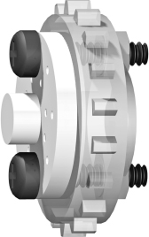
Figure 26-22 Hardware detail for mounting a small round servo horn onto the drive sprocket that comes in the Tamiya Track and Wheel Set.
Unlike a differentially steered two-wheel bot, where it is possible to turn by simply stopping one wheel, this is not advisable with a track drive. The track exposes too much surface area to the ground, which greatly increases friction. The stopped track will skitter over the ground (and possibly come off), and turning is harder to control.
SPECIAL CONSIDERATIONS FOR RUBBER TREADS
Because of size, cost, and weight concerns, the track material on most robot tanks is rubber. Rubber has a higher compliance than plastic or metal. If the robot is operated over a surface that is also fairly compliant (means having resiliency or “give”), turning may be difficult for the little tank.
Another potential issue of using a rubber tread is static friction, or stiction. (There may be other frictional components involved, but we’ll bypass them for this discussion.) With stiction, a rubber tread may have difficulty skidding over a highly polished material, such as a glass tabletop or hardwood floor.
There are numerous techniques to reduce the steering problems inherent in all treaded vehicles. One is to use a less compliant tread material. Not all rubber compounds are equally elastic. A good rubber tread for a tank design exhibits only limited elasticity (stretch). The surface of the rubber is smooth and may have molded-in “cleats” that reduce the surface area of rubber touching the ground at any one time. With less surface area, there is less rubber to skid.
USING PLASTIC TREADS
An alternative to rubber treads is tracks of hard plastic. An example is the track for the Vex Robotics Design System. The kit, which is designed for the Vex line of robots but can be adapted to other applications, consists of a series of plastic links that you put together.
Another example of hard plastic tracks comes from an outfit named JohnnyRobot and is sold by a number of specialty online robotics sources (see Appendix B for Web sites). These tracks are composed of ABS plastic links, connected by miniature stainless steel rods. You connect the links together to make a track any size you want.
Plastic sprockets and idlers are also available to make a complete tracked system. Drive sprockets are available for Futaba and Futaba-style servo motors, Solorbotics, and other DC motors that use 7mm double-flatted driveshafts. Figure 26-23 shows a complete track drive subsystem that uses the JohnnyRobot links, ready to be mounted on a base. Of course, you need two of these drive subsystems to make a completed robot.
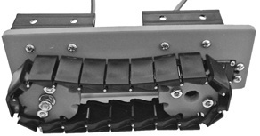
Figure 26-23 All-plastic treads on a custom-made tank-style drive subsystem. Just attach the subsystem to a base to complete the robot.
If there is a disadvantage to hard plastic tracks, it’s that the plastic may slip over hard surfaces—the exact opposite of rubber treads. Depending on the design of the track, you may be able to overcome this by applying small pieces of rubber material over the track segments. This provides enough compliancy to improve locomotion and steering.
DEALING WITH DETRACKING
Rubber and plastic tracks (or metal tracks, for that matter) differ in their resistance to detracking—also called derailing, or “throwing a track.” Detracking occurs mostly when negotiating a turn. This is when the frictional forces acting against the track are at their highest. As the vehicle attempts to turn, heavy sideways pressure is exerted at the front and back of the track. If the pressure is great enough, the track may come off its drive sprocket or guide rollers.
Detracking rears its ugly head the most when using highly elastic rubber treads. The more elastic the track material, the more readily it will stretch during a turn. The problem is magnified if the tank is loaded down with weight. The heavier the vehicle, the more likely you’ll have a thrown track. To limit this problem:
![]() Reduce the weight on the vehicle.
Reduce the weight on the vehicle.
![]() Make slower turns.
Make slower turns.
![]() Try to find a rubber tread that doesn’t stretch as much. The lower the elasticity, the less likely the tread will pop off.
Try to find a rubber tread that doesn’t stretch as much. The lower the elasticity, the less likely the tread will pop off.
![]() As necessary, tighten the track by adjusting the distance between the drive sprocket on one end and the idler roller on the opposite end. This limits the track from stretching too much more. Avoid overtightening, which can deform the tread and place excessive stress on the drive components.
As necessary, tighten the track by adjusting the distance between the drive sprocket on one end and the idler roller on the opposite end. This limits the track from stretching too much more. Avoid overtightening, which can deform the tread and place excessive stress on the drive components.
![]() Decrease the surface area of the tread on the ground. You may do this by changing the elevation of the idlers toward the front and back.
Decrease the surface area of the tread on the ground. You may do this by changing the elevation of the idlers toward the front and back.
![]() Experiment with the width between the tracks. Longer, narrower track widths resist turning more than shorter, fatter widths.
Experiment with the width between the tracks. Longer, narrower track widths resist turning more than shorter, fatter widths.
![]() Add “keepers” to the idlers that don’t touch the ground. The keepers are like oversized rims that keep the track in place.
Add “keepers” to the idlers that don’t touch the ground. The keepers are like oversized rims that keep the track in place.
By their nature, plastic and metal tracks don’t stretch, so, assuming they are placed snugly onto the sprocket and idlers, detracking is rare.