
Chapter 29
Experimenting with Robotic Grippers
Arms aren’t much good without hands. In the robotics world, hands are usually called grippers (also end effectors) because the word more closely describes their function. Few robotic hands can manipulate objects with the fine motor control of a human hand; they simply grasp or grip the object, hence the name gripper. Never sticklers for semantics, I’ll use the terms hands and grippers interchangeably.
Gripper designs are numerous, and no single design is ideal for all applications. Each gripper technique has unique advantages over the others, and you must fit the gripper to the application at, er, hand. This chapter outlines a number of useful gripper designs you can use for your robots. Most are fairly easy to build; some even make use of inexpensive plastic toys. The gripper designs encompass just the finger or grasping mechanisms.
Concept of the Basic Gripper
In the world of robotics there are hundreds of ways to make a gripper. The designs tend to be application-specific: like Captain Hook in Peter Pan, a metal hook offers advantages a normal hand cannot. A perfectly useful gripper might be designed for a single task, like collecting Ping-Pong balls or picking up chess pieces—whatever the robot is made to do.
Figure 29-1 shows a typical robotic gripper, depicted in three different states: all the way open, halfway open, and all the way closed. This style of gripper uses “fingers” that stay parallel as they open and close. The design allows the gripper to apply even pressure on either side of an object and close in on the object without pushing it away. The mechanism is not difficult, but you can see that it adds a bit of complexity to the construction of the gripper.
To be useful, most grippers are attached to the end of an arm. If the arm is on a wheelbase, the bot can steer around the room looking for things to pick up and examine. By orienting the gripper vertically or horizontally via a rotating wrist mechanism, the robot can grasp all manner of objects.
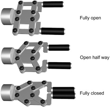
Figure 29-1 Robotic gripper in three states: all the way open, closed, and midpoint. In each case the “fingers” of the gripper remain parallel.
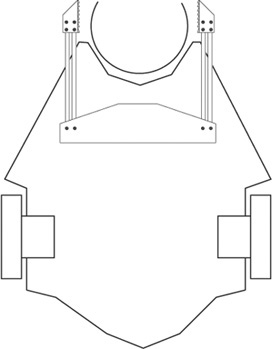
Figure 29-2 Grippers may be mounted directly on the base of a robot and used in specialty applications, such as collecting and holding balls, cans, or eggs.
There’s no rule that says the gripper must be attached to an arm; it can be connected directly to the robot itself. Figure 29-2 shows a “two-finger” gripper at the front of a robot base that collects balls. A cup indentation at the front of the robot serves to capture the ball, and a gripper holds the ball in place as the bot steers around the room.
Two-Pincher Gripper
The two-pincher gripper consists of two movable fingers, somewhat like the claw of a lobster. The steps for constructing several models are described in this section.
BASIC MODEL
For ease of construction, the basic two-pincher gripper is made from extra Erector set parts (the components from a similar construction kit toy may also be used). Cut two metal girders to 4-1/2″ (since this is a standard Erector set size, you may not have to do any cutting). Cut a length of angle girder to 3-1/2″. Use 4-40 or 6-32 × 1/2″ machine screws and nuts to make two pivoting joints. Cut two 3″ lengths and mount them (see Figure 29-3). Nibble the corner off both pieces to prevent the two from touching one another. Nibble or cut through two or three holes on one end to make a slot. As illustrated in Figure 29-4, use 4-40 or 6-32 × 1/2″ machine screws and nuts to make pivoting joints in the fingers.
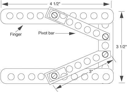
Figure 29-3 Construction detail of the basic two-pincher gripper, made with Erector set (or similar) parts.
The basic gripper is finished. You can actuate it in a number of ways. One way is to mount a small eyelet between the two pivot joints on the angle girder. Thread two small cables or wire through the eyelet and attach the cables. Connect the other end of the cables to a solenoid or a motor shaft. Use a light-compression spring to force the fingers apart when the solenoid or motor is not activated.
You can add pads to the fingers by using the corner braces included in most Erector set kits and then attaching weather stripping or rubber feet to the brace. The finished gripper should look like the one depicted in Figure 29-5.
ADVANCED MODEL
You can use a readily available plastic toy and convert it into a useful two-pincher gripper for your robot arm. The toy is a plastic “extension arm” with the pincher claw on one end and a hand gripper on the other (see Figure 29-6). To close the pincher, you pull on the hand gripper. The contraption is inexpensive—usually under $10—and it is available from many online toy stores.
Chop off the gripper 3″ below the wrist. You’ll cut through an aluminum cable. Now cut off another 1-1/2″ of tubing—just the arm, but not the cable. File off the arm tube until it’s straight, then fashion a 1-1/2″ length of 3/4″-diameter dowel to fit into the rectangular arm. Drill a hole for the cable to go through. The cable is off-centered because it attaches to the pull mechanism in the gripper, so allow for this in the hole. Place the cable through the hole, push the dowel at least 1/2″ into the arm, and then drill two small mounting holes to keep the dowel in place (see Figure 29-7). Use 6-32 × 3/4″ machine screws and nuts to secure the pieces.

Figure 29-4 Hardware assembly detail of the pivot bar and fingers of the two-pincher gripper: (A) assembled sliding joint; (B) exploded view.

Figure 29-5 The finished two-pincher gripper, with fingertip pads and actuating cables.
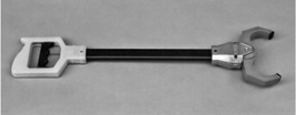
Figure 29-6 A commercially available plastic two-pincher robot arm and claw toy. The gripper can be salvaged for use in your own designs.
You can now use the dowel to mount the gripper on an arm assembly. You can use a small 3/4″ U-bolt or flatten one end of the dowel and attach it directly to the arm. The gripper opens and closes with only a 1/2″ pull. Attach the end of the cable to a clevis (available at hobby stores), then connect that to a servo horn (Figure 29-8).
CONSTRUCTING PARALLEL FINGER GRIPPERS
Figures 29-9 through 29-12 show another approach to constructing two-pincher grippers. By adding a second rail to the fingers and allowing a pivot for both, the fingertips remain parallel to one another as the fingers open and close. You can employ several actuation techniques with such a gripper. Only basic plans are provided here to give you an idea of how these grippers work. Feel free to experiment to come up with unique designs of your own.
Tool Clamp Gripper
I figure if someone else has gone to the trouble and expense of making a product that just happens to work in robot projects, the least we can do is take advantage of their kindness!
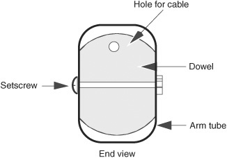
Figure 29-7 Assembly detail for the claw gripper and wooden dowel. Drill a hole for the actuating cable to pass through.

Figure 29-8 One method for actuating the gripper: Attach a solid aluminum cable from the claw to a clevis end (available at hobby stores) and servo horn. An R/C motor turns the horn, pulling or pushing the cable and opening or closing the gripper.

Figure 29-9 Adding a second rail to the fingers and allowing the points to freely pivot causes the fingertips to remain parallel to one another.

Figure 29-10 Close-up detail of the dual-rail finger system. Note the pivot points.
In this project you use an ordinary plastic tool clamp, available at dollar stores and discount tool outlets, as a motorized robotic gripper. An R/C servo motor opens and closes the clamp. This gripper is simple to build and surprisingly strong.
Plastic tool clamps come in a variety of shapes and sizes. You want one that’s as close as possible to the clamp in Figure 29-13. The clamp measures 5″ in overall length and is about 1-1/2″ wide when the clamp is closed. The clamp is fitted with a plastic locking mechanism, which you’ll remove as part of the construction steps outlined as follows.
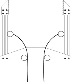
Figure 29-11 A way to actuate the gripper. Attach cables to the fingers and pull the cables with a servo motor. Fit a torsion spring (a thin metal strip) along the fingers and palm to open the fingers when power is removed from the motor.
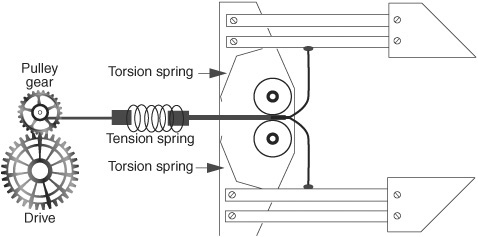
Figure 29-12 Actuation detail of a two-pincher gripper using a motor and gears. The tension spring prevents undue pressure on the object being grasped. The torsion springs are thin pieces of brass that act to reopen the gripper fingers when the motor shuts off.
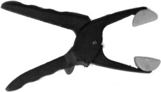
Figure 29-13 Small plastic tool clamp used in the tool clamp gripper.
CUT OUT GRIPPER MOUNT
Using 6mm expanded PVC or 1/4″ hobby or aircraft plywood, cut the mount of the gripper as detailed in Figure 29-14. The only true dimension-sensitive cut is the inside of the servo mount.
This cut is best made by drilling a hole at one corner, then threading a thin (woodworking) coping saw blade through the hole. Attach the blade to the coping saw, and carefully cut the rectangular hole for the servo. Be sure not to cut away too much, or you won’t have room for the servo mounting holes.

An alternative is to saw a pocket for the servo by cutting at the dotted lines, as noted in Figure 29-14. This kind of cut can weaken the mount because there’s supporting material on just three sides rather than four. But all or most of the strength will return when the servo is mounted in the pocket. Use all four servo mounting screws in this case.
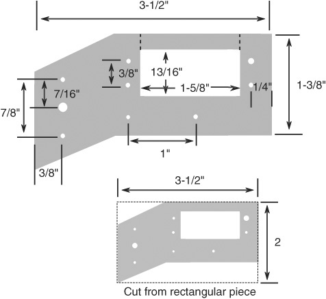
Figure 29-14 Cutting and drilling layout for the mount for both R/C servo motor and tool clamp.
ATTACH SERVO TO THE MOUNT
Using 4-40 × 1/2″ machine screws and nuts, attach a standard-size servo to the gripper mount, as shown in Figure 29-15. The angled portion of the mount should face toward the right. The servo shaft should be closest to the angled portion of the mount.
If you’d like to add a side-to-side wrist joint to the gripper, attach a double-arm servo horn (it should come with the servo) to the angled portion of the mount, also using 4-40 × 1/2″ machine screws and nuts. The nuts should be on the “top” of the mount (same side as the servo output shaft), and the horn should be on the bottom.
PREPARE AND MOUNT THE CLAMP
Prepare the clamp by first removing the plastic locking mechanism. I’ve found the best way is to simply use brute force: start by releasing the lock and opening the clamp all the way. Using a pair of heavy-duty pliers, grip the locking mechanism and literally tear it out. If any pieces of the locking mechanism remain inside, nudge them out with a small flat-bladed screwdriver.
You may ruin the first clamp you try to modify this way, so better get two at the store just in case. They’re not that expensive, and, besides, in many instances they sell a pair of clamps in one package. That’s how I’ve always bought them.
Drill three 1/8″-diameter holes, as noted in Figure 29-16. On one handle you drill two holes; the spacing must match the holes in the mount. The other hole is for the servo linkage, and its exact position isn’t critical. Make sure you drill all the holes in the approximate middle of the clamp handles.
Drilling complete:
1. Attach the clamp to the gripper mount using 4-40 × 3/4″ machine screws and nuts.
2. Attach a double-arm horn or adjustable arm horn to the servo. (When using a double-arm horn, cut off the opposite arm.)
3. Using your fingers, slowly center the gripper servo to its midpoint.
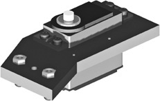
Figure 29-15 R/C servo motor attached to the mount. Note the orientation of the output shaft of the servo motor.

Figure 29-16 Drill three holes for mounting the tool clamp and for attaching the activating rod from the servo motor.
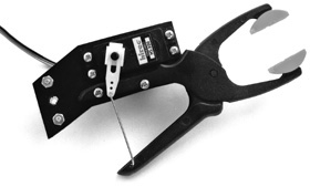
Figure 29-17 Finished tool clamp gripper, showing the activating rod between the clamp and the R/C servo motor.
4. Cut a 1″ (approximate) length of solid music (also called piano) wire, available at the hardware store. Actually, I just use a piece of wire cut off from an extra-large metal baby safety pin—you can get a dozen for just a dollar or two at the local discount store. A pair of lineman’s pliers easily cuts the wire.
5. Using pliers, bend 1/4″ or so at the ends of the wire.
6. Place one bent end into a hole in the servo horn and the other into the empty hole you drilled in the clamp handle.
7. Once you’re sure the wire is the right length (move the servo back and forth a few times), use a pair of pliers to cinch the wire securely in place. You don’t need or want to clamp the wire shut, just close it up a bit so it won’t easily fall out.
The completed tool clamp gripper is shown in Figure 29-17. At the base of the gripper is another double-arm servo horn, for attaching to a servo that’s mounted on the robot. This servo lets the gripper scan back and forth for its prey. You don’t need to use this servo horn if you’re planning on bolting the gripper directly to your robot.
On the Web: More Gripper Plans
Visit the RBB Online Support site (see Appendix A) for bonus gripper plans, including a solenoid-driven “clapper” two-pincher gripper, fingers that open and close using a homemade worm gear system, and ideas on how to construct flexible fingers that have a human-like compliant grasp.